Close
0%
0%

operation: Learn The MIPS (PIC32MX1xx/2xx/370)

Having been exclusive to a certain uC-line for over a decade, it's time to learn something new (and port commonCode!)... Enter MIPS

Similar projects worth following
Nearly every microcontroller-based project (which is nearly every electronic project) I've done over the past decade+ has been based on a particular line of microcontrollers I'll leave nameless (here).

It's time to learn something new, and maybe soon port my [other uC] libraries to them as well.

First start was roundabout. Recently moved, I needed a project and had very little unboxed to work with. Ended up taking apart an old [TV] Cable Box and discovered the undocumented Freescale chip to be MIPS32-based. Learnt quite a bit about OpenOCD, JTAG, MIPS, and more... and even managed to get the Power and Message LEDs to blink.

Next, the discovery that the Microchip PIC32 series is based on MIPS!

Plausibly, the non-open-source entry-requirements for this line are nill, unlike [my understanding of and deterrent from] the normal PIC line. Planning to use only open-source tools, like the FTDI-based JTAGger, gcc-mips, and a few others...

NOTE: I'll be focussing this project on the chips I have at-hand: The PIC32MX1xx/2xx series DIP28's. Further, this project aims to run "bare-metal" code, rather than, say, running [applications atop] an operating-system.

For the past decade+ I've been developing code for AVRs... much of that has become common "libraries" that I use from project-to-project. Many of those "libraries" (and the system that makes them possible) are completely "architecture-agnostic."

Those libraries and the system, I call "_commonCode", are slowly being released to the public-domain via: #commonCode (not exclusively for AVRs)

Many of those libraries can be run on a desktop-PC, mostly for testing/debugging-purposes. But many such libraries would be quite difficult to simulate in that environment (e.g. motor-driver code). These sorts of libraries would be best-made more "architecture-agnostic" by having a new architecture to run them on... causing me to revisit the code to see where/if architecture-specific code still exists and abstract that code as necessary.

In the process, I'll be messing with MIPS/PIC32... Attempting to get the system running in an entirely open-source manner (no device-specific programming-dongles to purchase, no crippled Windows-Only IDE). (NOTE: I have resorted to using the Microchip-supplied free 'xc32-gcc' package, as it comes pre-configured with header-files and linker-scripts... This package is *free* and available precompiled for Windows, OSX, and Linux. Maybe an entirely-open-source path can come in the future. Check out @jaromir.sukuba's page: https://hackaday.io/page/2437-myths-and-legends-of-pic-microcontrollers, which has some good info on the matter!).

I plan to use the same tools I used to blink the LEDs on my old [TV] Cable Box: an FTDI-based JTAGger, openOCD, gdb, gcc, etc.

Further, these tools could then be added to the options in _commonCode, allowing for seamless programming/flashing and configuring of these devices in using same "architecture-agnostic" methods currently implemented (e.g. 'make run' flashes the device or executes the executable, depending on the architecture).

NOTES:

BEWARE OF int8_t math bug!!!! https://hackaday.io/project/6450-operation-learn-the-mips-pic32mx1xx2xx/log/23899-optimizer-bug

PPS-370-64.ods

Peripherals, both remappable and non-remappable for the PIC32MX370 64-pin variety. This is sorta project-specific, but should easily be modified for your own needs. Spreadsheet Written in LibreOffice

spreadsheet - 38.53 kB - 02/17/2016 at 04:05

Download

  • 1 × Microchip PIC32 Several from this line
  • 1 × Motorola DCT700 Cable Box with Freescale Processor Not necessary for PIC32 development, but was a huge tool in my MIPS/JTAG learning-process.
  • 3 × 0.1uF Ceramic Capacitors
  • 1 × 10uF Tantalum/Ceramic Capacitor (low ESR) I used two parallel 4.7uF Tantalums
  • 1 × JTAG adapter openOCD-compatible: e.g. I used an FTDI FT2232H breakout-board

View all 10 components

  • BEEN USING...

    Eric Hertz10/19/2016 at 14:32 0 comments

    I've been using three different variants of the PIC32MX-series for quite some time, now...

    The logs, 'round here, are a bit confusing, as there's a lot of mention of difficulties, and little explanation of accomplishments. Bad Me.

    So, yes, it works.

    (Yes, I'm using the xc32-gcc compiler, with free-license from Microchip, and Yes, the math-bug seems to have been fixed in the latest version).

    Yes, I have been using them for some time.

    Yes, I am programming them via openOCD and a FT2232H breakout-board via JTAG.

    Yes, I have managed to whittle that down to a couple bash-scripts and makefile snippets 'make run' which don't require any user-interaction.

    Yes, programming via JTAG takes a matter of seconds, now, rather than minutes.

    I don't recall all the details of *how* I managed all this, it's all scripted now, but rereading my logs, here, am reminded that some amount of "magic" was involved...

    So... where's that leave us...?

    I guess, at this point, if you're interested in going this path, lemme know... enough "lemme knows" and I'll try to piece together exactly how I pulled it together, and dig/throw up the source-code mods, etc. as I find them.

    Oh, and check out @jaromir.sukuba's page: https://hackaday.io/page/2437-myths-and-legends-of-pic-microcontrollers/discussion-67635 wherein you might get ideas for how to go the open-source route, which I've yet to accomplish.

    BE SURE TO check out the "instructions" on this project's page... There seems to be some information there about how to rebuild openOCD with the necessary hacks... and more.

  • A Question!!! PBCLK Divisor 1:1 and SFRs

    Eric Hertz06/26/2016 at 15:38 0 comments

    OK, so darn-near every register says something like "If you're using a peripheral-clock-divisor of 1:1, then do not write this register in the instruction immediately following writing this value"

    ...

    Here's a quote from the datasheet:

    When using 1:1 PBCLK divisor, the user’s software should not read/write the peripheral SFRs in the
    SYSCLK cycle immediately following the instruction that clears the module’s ON bit.

    I have no idea what to search for, search-fu-fail, but it seems like it must be a common-enough thing...

    Can we rely on xc32-gcc to make sure this never happens?

    The obvious solution, not knowing, is to use a slower peripheral-clock (e.g. 1:2), but yahknow, sometimes yahs wants the speed, or need a ratio that's not 1:2^n where n>0, or something.

    Has anyone run into the 1:1 PBCLK being an issue?

  • xc32-gcc Optimizer Math Bug Fixed in v1.42

    Eric Hertz06/20/2016 at 07:35 0 comments

    Alright! It's been 9 months since I submitted the bug, but it appears that the latest greatest xc32-gcc has Fixed It!

    The ol' bug was described, experimented-with, and characterized in great-detail here: https://hackaday.io/project/6450-operation-learn-the-mips-pic32mx1xx2xx370/log/23899-optimizer-math-bug

    Basically, what it boiled down to was that if you used -O1, (optimization, at the highest-level available in the "free" xc32-gcc), then math-errors would occur with uint8_t and int8_t. It seems what happened, on rare occasion (which I just happened to be lucky enough to encounter in my first project) was that the optimizer would treat int8_t as though they were 32-bit, and forget to pad the remaining-bits. It could've worked, if it padded them correctly, but it didn't. So, e.g. I had something like

    int8_t direction = -1;
    uint8_t power = 127;
    
    int16_t signedPower = (int16_t)direction * (int16_t)power;

    And, instead of getting -127, I was getting 32385. Yep, 32385 = 0xff * 127. And we all know that -1 is 0xff, when represented in an int8_t, right...?

    Except, it didn't happen *all the time*... you'll have to look at the details of the link above to see *when* it happened, but it did happen, and when driving a motor, the difference between a power-level of -127 and 32385 could've caused quite a bit of finger-damage to the unwary.

    This, apparently, having tested, only occurred on the linux version of xc32-gcc (v1.40)... I tried the exact same code under WinXP, and it worked fine.

    So, I thought I got the ol' brush-off, because I never saw an update, and even looking through changelogs between v1.40 and v1.42, no mention of it... But I tried v1.42 anyways, and yep, it works.

    Woot!

    Apparently I inadvertently discovered another bug, as well... by having a bug within my own code... I used "\n" to end one line, and "\n\r" to end those thereafter... And, of course, I was outputting via serial-port, where a lone "\n" isn't enough to carriage-return back to column-zero as well...

    In 1.40, it displayed as I'd intended... (despite my bug)

    But in v1.42 it displays funky... "Almost as though" it's not returning to column-zero before starting the new-line...

    Yep, I forgot a "\r" and they fixed not only the math-bug, but also the carriage-return "bug." Woot!


    There may be more in a bit... I've yet to reimplement -O1 in a regular-ol' project to see how my code functions... logically, there should be one level of optimization greater than what it was before, so it might be a bit faster... OTOH, my workaround for the math-bug was to use -O0 and enable all the -f<options> I could find... so... we shall see.


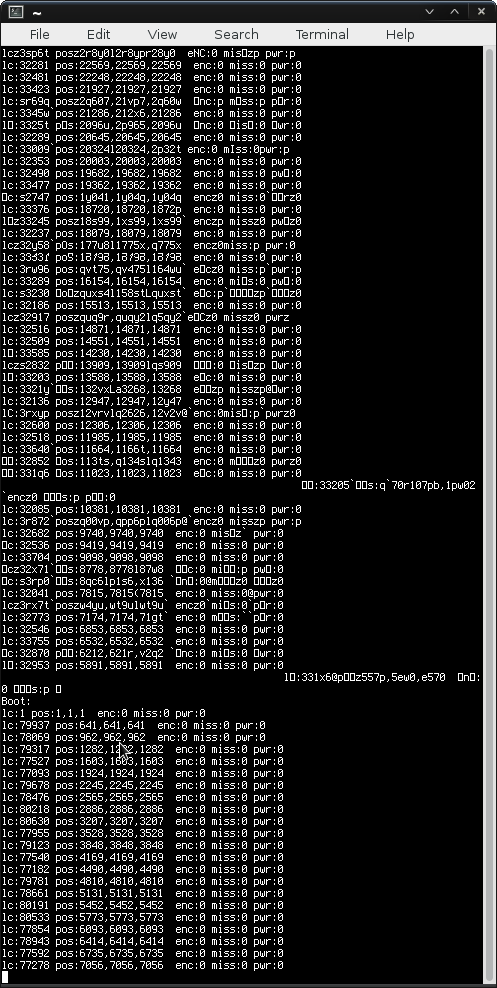
    Indeed, my "loop-count/second" has increased from around 32,000 to 80,000 by being able to use -O1 instead of all the -f<options> explicitly. And now my bit-banged UART works darn-near perfectly:

    ("Why would you use a bit-banged UART on a chip which has a built-in UART peripheral...?" that's another topic entirely...)

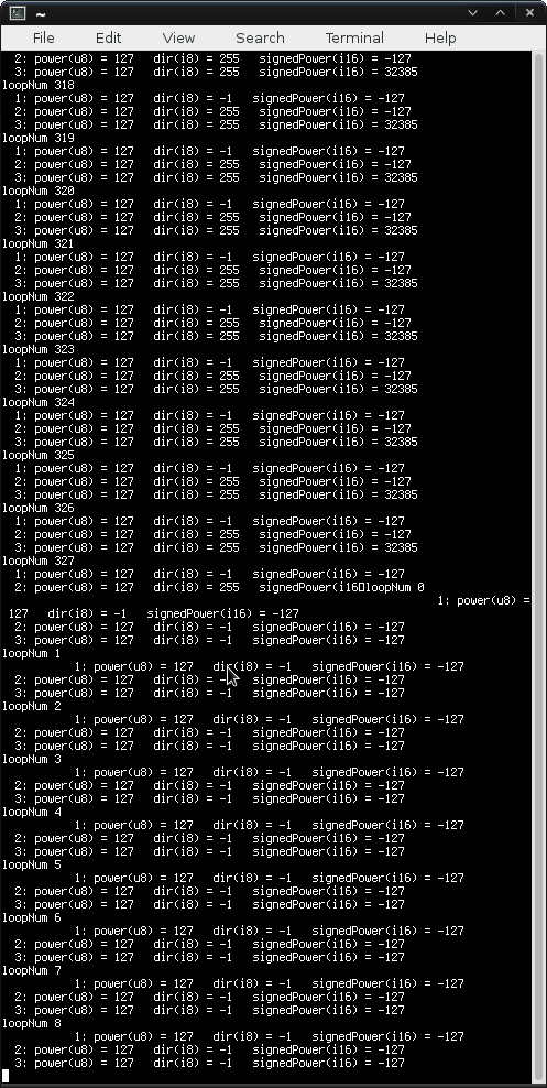
    And here's a showing of the carriage-return bug-fix. The earlier lines shouldn't've been aligned as they are, I forgot "\r"... The later lines show "1:" shifted as it should be with merely a "\n", when sent via serial-port...

    I had "\n" after the "loopNum" statement, but "\n\r" after all the other statements... The old version (v1.40) apparently automatically appended the "\r" (!?), but the new version (v1.42) doesn't, so it works as-expected per the coding, which had a bug in it.


    Now, Microchip, I may have "lucked" into discovering the math-optimization bug, but it was actually a tremendous amount of effort, on my part, to determine how to reproduce the bug, how to present it in a way that didn't include the thousands upon thousands of lines of code that I discovered it in, etc... And you lucked-into the fact that I happened to be willing to go to all that effort (hours, MANY MANY hours) to present it to you... submit it as a ticket, even work with your employee.. When I'd already found a workaround for my own purposes using the "-f<options>" and disabling...

    Read more »

  • PIC[32]sy

    Eric Hertz09/29/2015 at 11:10 0 comments

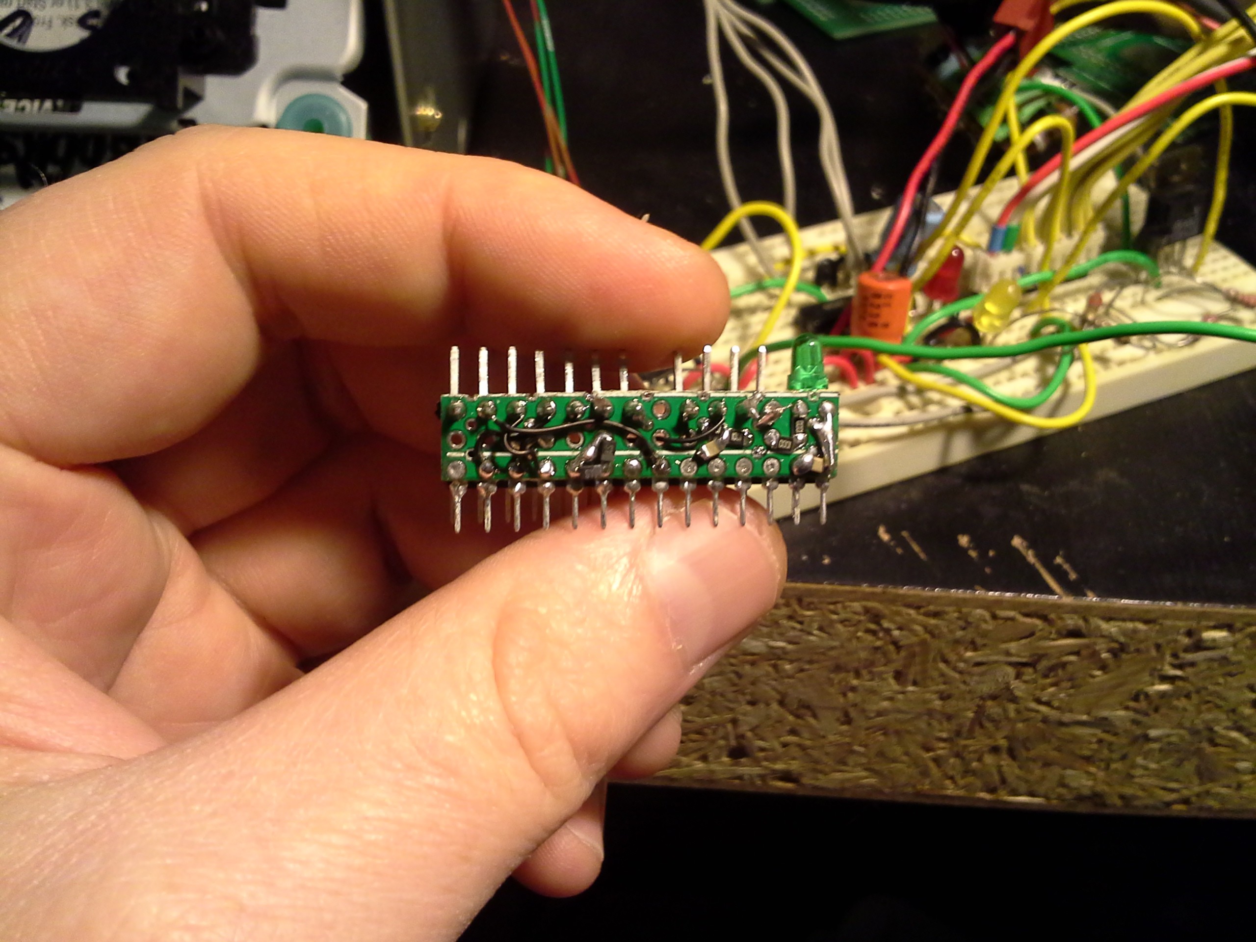
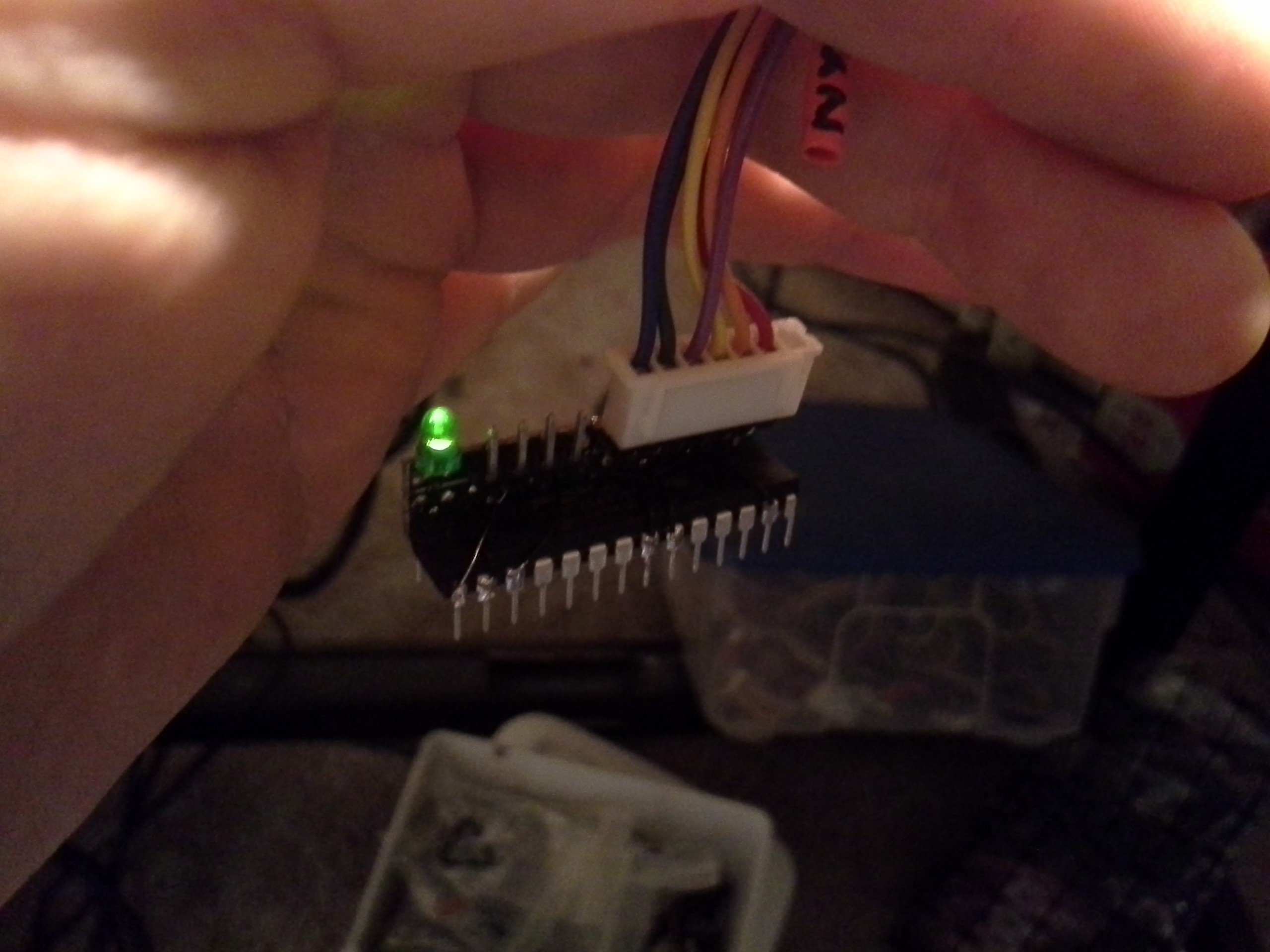
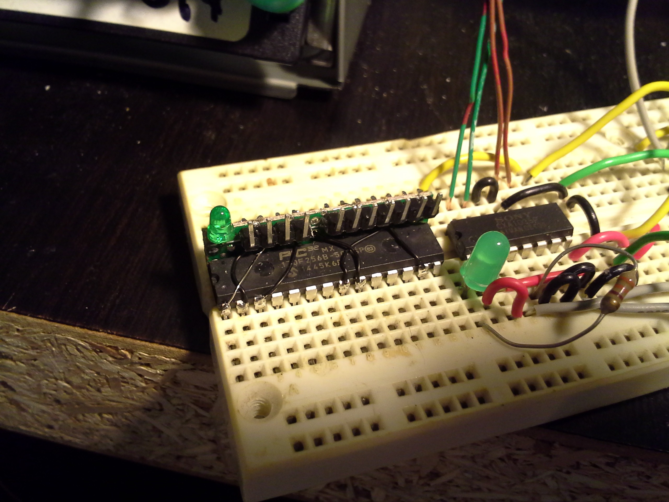
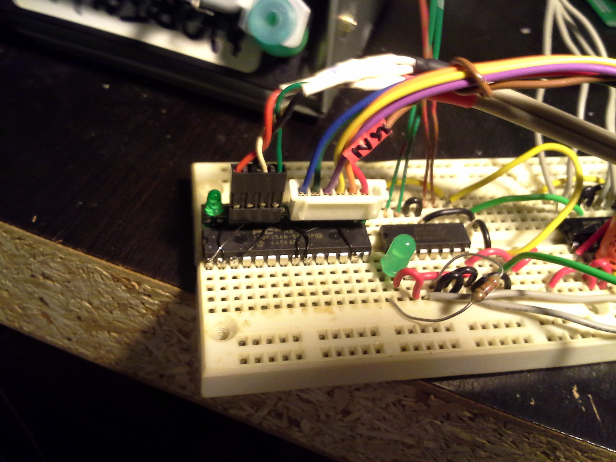
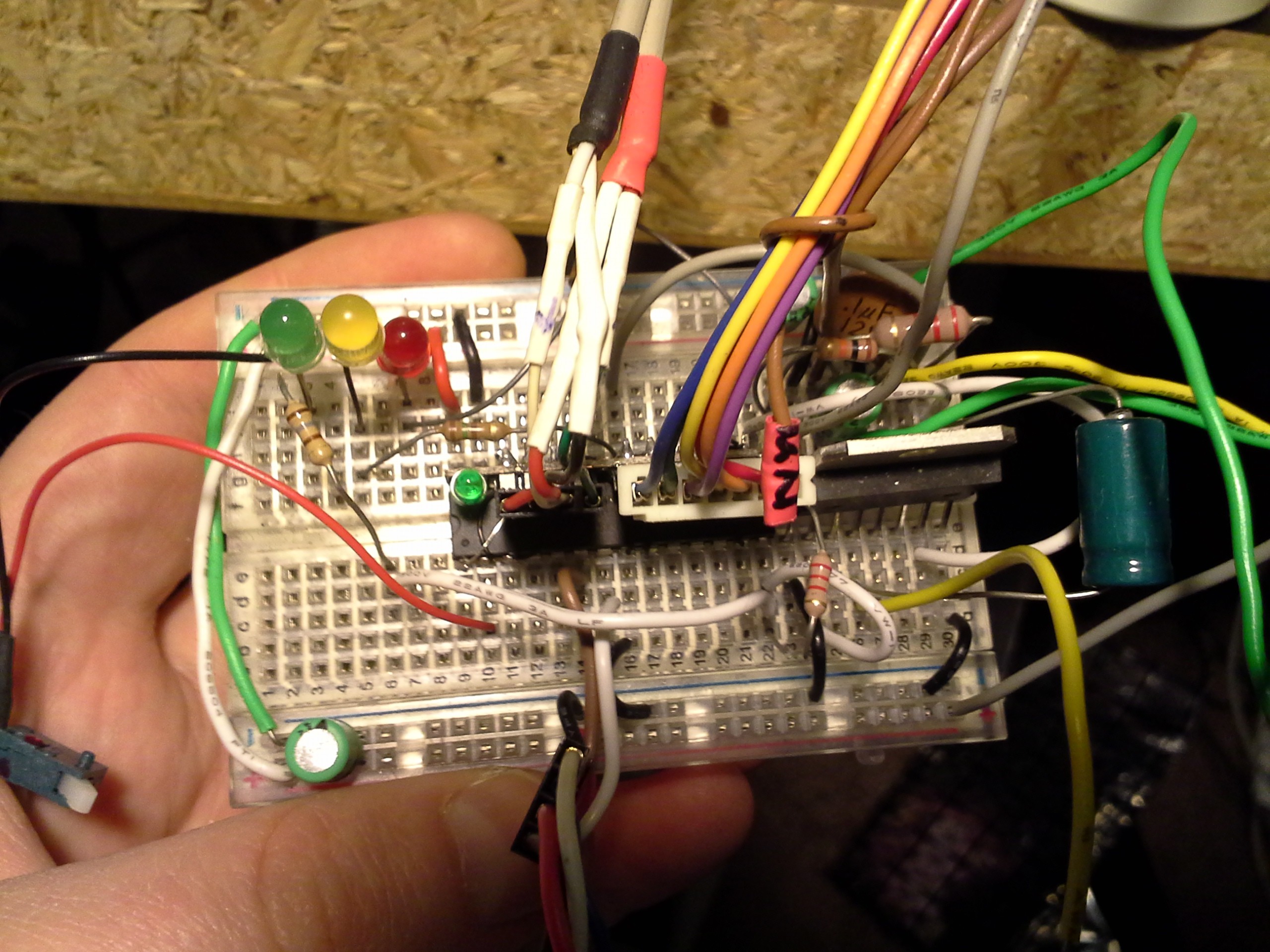
    Update: Adding before-and-after images of it in-circuit.

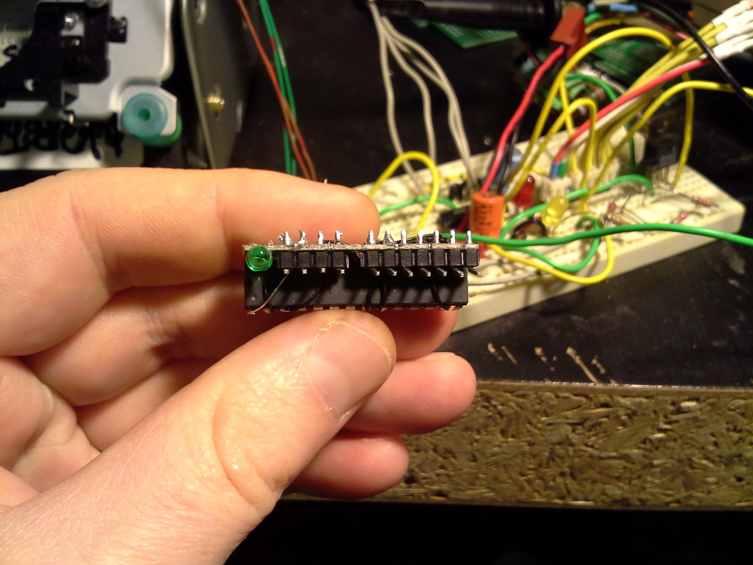
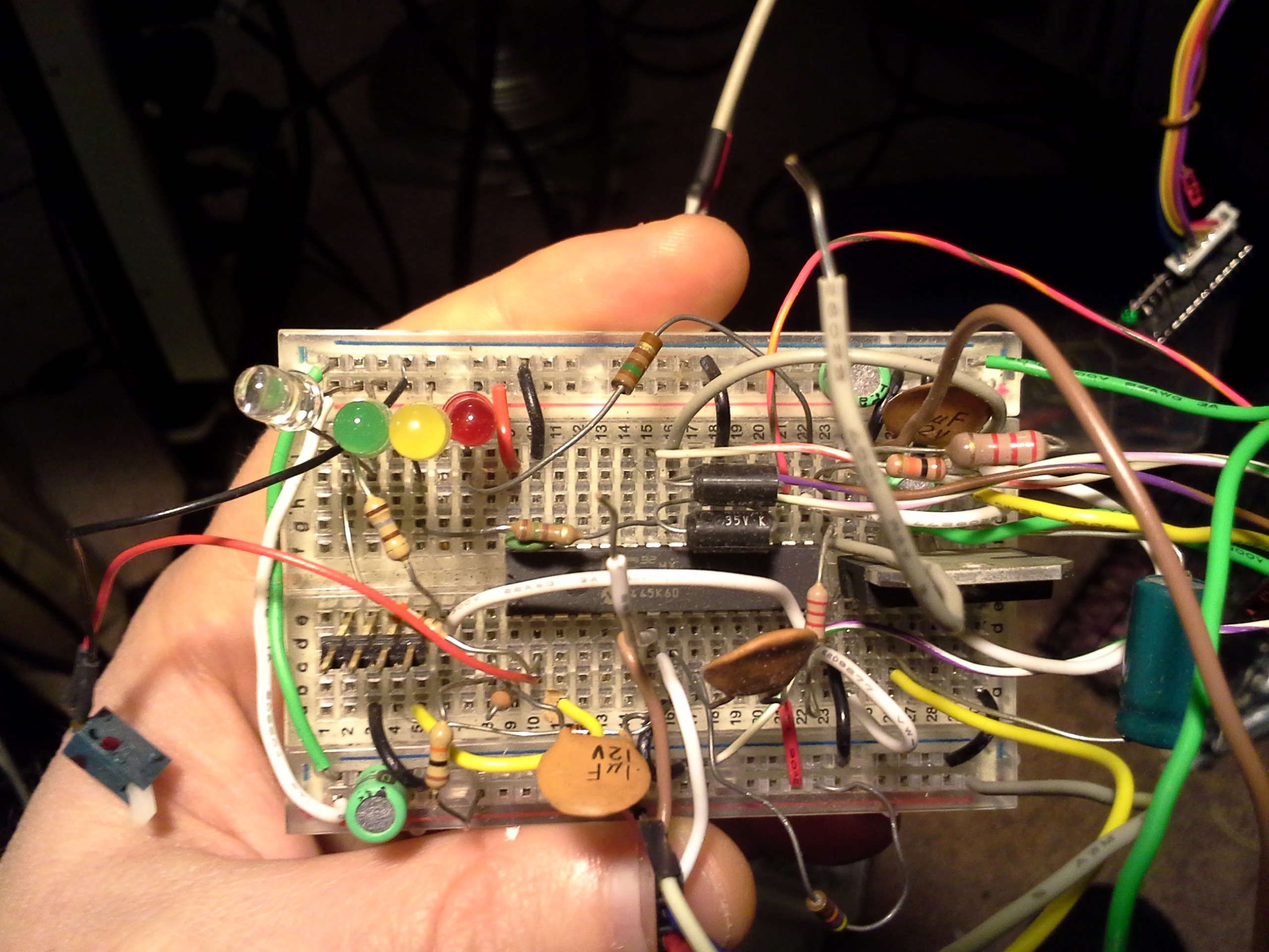
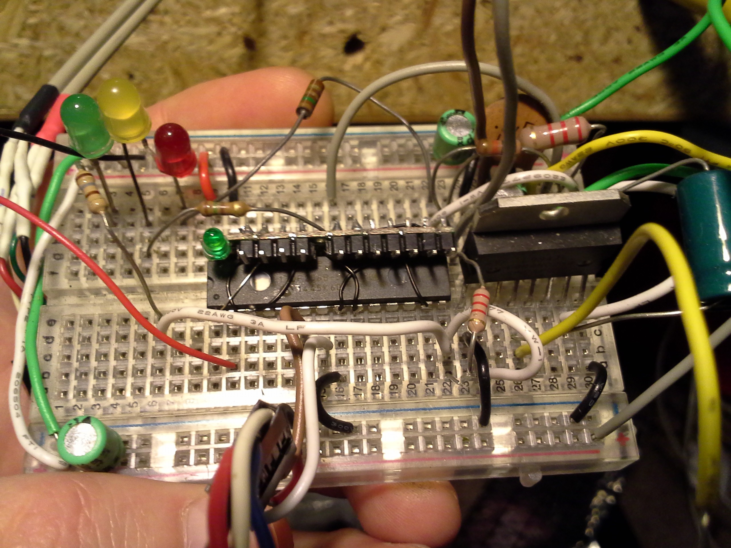
    The problem is, there's quite a bit of bare-minimum support-circuitry with the PIC32 (and probably most newer high-speed microcontrollers), including several capacitors, some resistors for the reset pin, and several power pins. Add to that, all my projects use a heartbeat LED, 9/10 also use serial I/O, and of course I need the programming-header (JTAG, in my case).

    I still want to breadboard with this, but the bare-minimum, alone, creates quite a rat's nest, at least the way I breadboard...

    Originally I planned on placing a PCB flat atop the chip... @antti.lukats's design for DIPSY, with its upright pins, was definitely a contributing-factor in this layout idea... But I had some difficulty figuring out how to do that with through-hole parts like the header-pins... and staring at it for a while, it finally came to me!

    (Next time I'll use actual right-angle headers, instead of bending straight ones).

    This is actually handy-enough I might do it with through-hole AVRs, etc. as well... So I'm thinking with my next custom PCB-run I'll include something like... what're those things called, not J-lead, right? Anyways, holes at the edge that are only half-circles, so they sit right atop a DIP's pins, where they enter its package. In this case, I just blobbed a ton of solder through the lowest row of holes until the blob finally reached the pins' faces. (The pins come out at a slight angle, so the PCB and its holes aren't actually resting flush on them).

    Most of the support-circuitry is connected to one side, but some wires needed to cross-over.

    Everything needed to run code is now "on-chip"... The heartbeat is fading in this image, and it's also outputting serial data (and responding to received data) on the unpopulated serial-header pins.

    And it still fits in the breadboard without occupying (almost) any additional breadboard space, and should probably still fit in "machine-pin" sockets. In fact, it should work fine in a circuit designed for this chip, e.g. on a PCB with the same support-circuitry on-board.

    The left connector is for (TTL-level RS-232) serial I/O. The right is JTAG.

    The other nice thing about the upright PCB, rather'n a flat one, is that the chip's part-number is still visible. Handy since I've got two in this family with slightly different pinouts/functionality.

    That piece of red-heatshrink says NYI and covers the currently unconnected/unhoused 7th pin... That's for SRST or TRST, should I ever find a use for it. Though, I'm almost certain I've read somewhere that neither are necessary (nor even implemented?) for PIC32 JTAGging... (I shoulda bookmarked that and posted it as a response in the earlier logs regarding the various JTAG resets...).

    Here's a "before and after" of my motor-driver project:


    Oh, and... starting to get the hang of this FT2232H breakout-board I've been using... Now making use of its second "channel" for the serial-port (and broke out pins for AVR programming, as well).

  • OPTIMIZER MATH BUG

    Eric Hertz08/22/2015 at 18:29 1 comment

    Update (6-20-16):

    The Bug Has Been Fixed In xc32-gcc v1.42. Get your updates!

    https://hackaday.io/project/6450-operation-learn-the-mips-pic32mx1xx2xx370/log/40265-xc32-gcc-optimizer-math-bug-fixed-in-v142

    And, interestingly, another bug I unknowingly uncovered was fixed, as well.

    Update (11-20-15):

    I have verified that this exists on the LINUX-x86 (32-bit) version of xc32-gcc v1.40, but NOT on the Windows(32-bit) version. I have not attempted to redownload the linux version of v1.40, as the version-number and date have not changed.

    Briefly, as I recall: It appears the Windows version results in a "load immediate (-1) to register" (also with a "sign-extend"? or was that on the linux version?), whereas the Linux version results in only a "load immediate to register (255)". Interestingly, *the entirety* of the rest of the disassembly of the code is *identical* except for the obvious 4-byte offset of jumps thereafter.

    Microchip has contacted me saying: "Our compiler team has tested it and got the expected/correct results... What version are you using?"--ish. Which is interesting, considering the code I submitted said *exactly* which version I was using...

    Also, take-note: When logging in to your account, apparently HTTPS:// is *not* default, on a friggin' login-page! But you can get there by typing it in manually. Weird.

    Update (10-15-15): CALL TO PIC32/xc32-gcc USERS!

    There is now fully-executable and thoroughly documented (as well as significantly simplified) code available at github: xc32_mathBugTester (see the README.TXT).

    I'm curious to know whether others run into the same problem. It shouldn't be difficult to modify for most PIC32's, but if you've a PIC32MX170F256B, and some spare time, you can run the already-compiled executable.

    This bug was originally submitted as a ticket to MICROCHIP on 9-20-15, per @jlbrian7's suggestion and sleuthing (Thanks, buddy!).

    This code was submitted today as a follow-up to a response from their tech-support today; he's "working with the compiler team."

    This is the simplified code which causes the bug (with -O1):

    //NOTE: 
    //  PRINT_IT() must be a MACRO, or inline calls to printf(),
    //    (not a function) for the bugs to occur.
    
    #define PRINT_IT(ID, power, dir, signedPower) \
      printf("  %d: power(u8) = %" PRIu8 \
             "   dir(i8) = %" PRId8 \
             "   signedPower(i16) = %" PRIi16 "\n\r", \
             ID, power, dir, signedPower);
    
    
    //This function *should* Print the following, in all cases:
    //  1: power(u8) = 127   dir(i8) = -1   signedPower(i16) = -127
    //  2: power(u8) = 127   dir(i8) = -1   signedPower(i16) = -127
    //  3: power(u8) = 127   dir(i8) = -1   signedPower(i16) = -127
    //
    //WITH OPTIMIZATION it prints:
    //  1: power(u8) = 127   dir(i8) = -1   signedPower(i16) = -127
    //  2: power(u8) = 127   dir(i8) = 255   signedPower(i16) = -127
    //  3: power(u8) = 127   dir(i8) = 255   signedPower(i16) = 32385
    
    //REGARDLESS of the *printout*, 
    //the horrendously-valued "signedPower" is actually used and assigned to the PWM 
    
    
    //NOTE: Many tests have been performed (no longer included in this code)
    // SEE main.c in the parent directory!!!
    void testBrokenMathAndPrintout(void)
    {
       uint8_t power = 127;
       int8_t dir = -1; 
    
    
       int16_t signedPower = (int16_t)power * (int16_t)dir;
    
       //"THE BUG" appears differently depending on how PRINT_IT is implemented
       // IN THIS FILE:
       // PRINT_IT() is merely a macro.
       //  Identical to including the printf() statement RIGHT HERE
       //  AND has the IDENTICAL result.
       PRINT_IT(1, power, dir, signedPower);
    
    
       //This case will SELDOMLY be *executed*
       // but without some *potential* reassignment to the variable 'dir' 
       // (somewhere) the bug does not appear
       // (Note how difficult it is to come up with a case that won't be optimized-out!)
       if(rand() == 0)
       {
          printf("!!! rand() == 0, else{} executed!\n\r");
          
          //THIS VALUE IS NOT EXPECTED TO BE USED
          dir = ((int8_t)(0));
       }
    
    
       PRINT_IT(2, power, dir, signedPower);
    
    
       signedPower = (int16_t)power * (int16_t)dir;
    
       PRINT_IT(3, power, dir, signedPower);
    }
    
    
    -------

    Update (9-20-15): Thanks @jlbrian7 for the...

    Read more »

  • This is getting confusing!

    Eric Hertz08/17/2015 at 16:40 0 comments
  • It shoulda been simple!

    Eric Hertz08/12/2015 at 14:58 2 comments

    UPDATE: FIXED!

    Apparently the MX170 is not yet in openOCD's device-listing:

    I don't fully understand it, and it was a VERY round-about way of coming to this rather simple conclusion. This does require recompilation of openOCD.

    1. Edit the file openocd-0.9.0/src/flash/nor/pic32mx.c
    2. Add your CPUTAPID (see note) to pic32mx_devs[] ('round line 120).
      1. NOTE, add the CPUTAPID & 0x0fffffff... or *drop* the first nibble... e.g. the MX170F256B has a CPUTAPID of 0x26610053, the line added looks like:
        1. {0x06610053, "170F256B"},
      2. NOTE2: Based on my understanding of the code, it looks like you can add your device listing anywhere in the list (it doesn't have to be sorted).
    3. Recompile openOCD and place the executable appropriately
      1. (either 'make install', or if already done with an older version, just copy src/openocd over /usr/local/bin/openocd)

    Was:

    "It shoulda been simple" the phrase of this era... re: flashing the MX170...

    Read more »

  • Finally!

    Eric Hertz08/11/2015 at 14:29 0 comments

    Things're getting a bit confusing 'round here, as many of my projects feed into each other... This project is a relative-go, as I've managed to get the early-stages of #commonCode (not exclusively for AVRs) running on the PIC32... First was 'heartbeat,' which was a bit of a hurdle because I didn't realize the default ADC-register-settings interfere with many GPIO pins. (I think there's a log about that). Also, some difficulties with the timer, and a few other settings here and there... (FYI: read carefully: the "primary oscillator" is *external*, most-likely for early testing you'll want the FRC "Fast R/C" oscillator, which is internal (also note, it's not highly precise... mine's running at 108%). The weird thing is... even when selecting an external oscillator, it actually ran... maybe the breadboard capacitance did it, or maybe the PLL doesn't run slower than a certain frequency, so assumes it's there... I dunno.

    OK, after 'heartbeat' usually comes 'polled-uat' which is a bitbanged UART (with only a transmitter). This should be an easy step, since the heartbeat's default functionality already assures the timer is set-up...

    The third step is usually 'polled-uar' which is the bitbanged UART's *receiver.* Again, this should be an easy step; the timer's already set-up, and the heartbeat code also has Input functionality running (push a button and the heartbeat changes from fading to blinking). Right, again, easier said than done... Apparently I chose a pin who, again, had *different* defaults than GPIO... So, rather'n fight it, I just ended up swapping to another pin.

    But, it didn't work. First-guess, the 108% thing was too much for bitbanged *input*... PCs are probably a bit more sophisticated in their UART reception than my code. So I scaled out that error... and everything died. And it's been dead for nearly a week. FINALLY I figured it out... My scaling managed to push some math to overflow... Actually, that was one of my earlier guesses, but my calculator (which I wrote) said it should fit in 32bits fine... Low-and-behold, my calculator was only showing the lower 32 bits, and actually the scaling needed 36. Woot! DAYS UPON DAYS to figure that shizzle out.

    On the plus-side, my calculator is new and improved! My polled_uat code has been cleaned up quite a bit, as well as a few other things here and there. Also some new ideas for abstracting 'heartbeat' a bit more.

    Anyways, suffice-to-say, these three 'commonThings', once running, are usually the basis for all my projects... and now we're ready to start a new, more-sophisticated project... Enter: #2.5-3D thing, wherein I'll be abstracting the motion-control aspects of 'commonCode' so they can function on PIC32, and hopefully more-easily be ported to most any architecture.

  • optimizer reliance follies

    Eric Hertz07/17/2015 at 10:59 5 comments

    GAH! I should just delete this whole ordeal.

    Read more »

  • GPIO Defaults CANNOT read pin input

    Eric Hertz07/14/2015 at 06:55 0 comments

    NOTE:

    (Update: Now, if I'da just read Tahmid's intro from the start, as well as all the way through its first section, then I'da saved a LOT of time!)

    Summary: Put this early-on in your code!

    //Pins which are shared with Analog peripherals default to ANALOG by
    //default... This causes all READS from PORTx to be 0
    //Set ANSELx bits to 0 for PORTx reads to be valid!
    //Below takes care of PORTA inputs, use ANSELB, etc. for PORTB...
    ANSELA = 0x0000;
    

    Read more »

View all 19 project logs

  • 1
    Step 1

    For this procedure, I will assume you're using:

    • PIC32MX230F064B
    • FTDI FT2232H breakout board

    These notes are tested on a Linux system, but these instructions should be helpful for OSX or Windows, as well.

    These instructions are for a 'bare-metal' configuration (as opposed to running an application atop an operating-system like Linux or BSD).

    These instructions are for command-line based utilities, NOT using an IDE.

    (Oh, and I'm certainly no expert, there are probably better instructions out there, somewhere...)

  • 2
    Step 2

    Wire up your PIC32's MINIMUM requirements as-shown:

    (a summary of the related Project Log)

    (NOTE: If this page wraps-weirdly, try *shrinking* your window-width, counterintuitively)

    ( '#' = MUST BE CONNECTED )
    ( '*' = 5V-tolerant )
    
    3V3
     ^
     |
     \
     / 10K           PIC32
     \                  MX2xxFxxxB       3V3
     /                ___________         ^
     |  1k           |    |_|    |        | .1uF
     +-/\/\-- /MCLR -|1*#     #28|- AVDD -+--||--.
     |        RA0   -|2       #27|- AVSS / AGND -+-> GND
    ===.1uF   RA1   -|3        26|- RB15
     |  PGED1/RB0   -|4        25|- RB14
     |  PGEC1/RB1   -|5        24|- RB13
     |        RB2   -|6     (#)23|- VUSB3V3 ---> 3V3
     v        RB3   -|7        22|- RB11
    GND<---- GND/VSS-|8#       21|- RB10     10uF TANT/CER
     ^        RA2   -|9       #20|- VCAP ----||--.
     |        RA3   -|10      #19|- VSS / GND ---+-> GND
    ===.1uF   RB4   -|11      *18|- RB9/TDO
     |        RA4   -|12      *17|- RB8/TCK
     +------ V+/VDD -|13#     *16|- RB7/TDI
     |       TMS/RB5-|14*     *15|- VBUS (N/C OK)
     v               |___________|
    3V3
    

    (For the 10uF capacitor, I used two parallel 4.7uF tantalums)

    The PIC32MX1xxFxxxB series minimum-wiring requirements should be *nearly* identical, though there are some minor, but important, pinout differences.

    (NOTE: RB0/RB1 are not available as GPIO by default, due to PGED1/PGEC1 being the In-Circuit Programmer pins!)

  • 3
    Step 3

    Wire the PIC32's JTAG pins to the FT2232H breakout-board/JTAGger:

    Pin Mapping:
    
    PIC32MX2xxFxxxB     JTAG signal    FT2232H (JTAGger)
    14                  TMS            AD3
    16                  TDI            AD1
    17                  TCK            AD0
    18                  TDO            AD2
    (GND)               (GND)          (GND)
    (3V3)               (3V3)          (3V3)
    
    NOTE: I'm assuming you're taking 3V3 FROM the FT2232H
          breakout-board, to *drive* the PIC32!
          (Add a large-ish (22+uF) capacitor where
           3V3 and GND enter your PIC32's breadboard)
    NOTE 2: I am NOT connecting nTRST nor nSRST at this
            point.

View all 6 instructions

Enjoy this project?

Share

Discussions

Cristian Paul Peñaranda Rojas wrote 07/21/2015 at 12:40 point

It is good you removed the open source from the project name, it was confusing. Although, had you looked and project pinguino.cc ?

  Are you sure? yes | no

Eric Hertz wrote 08/11/2015 at 13:57 point

Funny I didn't see this before...

I don't recall having open-source in the name, but definitely "try to go opensource" was always in the description... I did end up losing steam on that path, however... the non-open-source toolchain seems to work fine and is available for most OSs.  And, the method I'm using doesn't require a brand/device-specific dongle... can definitely get up-and-running with zero entry-cost if you have an FTDI FT2232H breakout board (which is a worthy tool for many purposes).

Thanks for the heads-up on pinguino! That looks to be a worthy adversary to arduinos :)

  Are you sure? yes | no

jaromir.sukuba wrote 07/07/2015 at 13:13 point

Honestly, I didn't read all the project logs. Yep, you can run completely open-sourced toolchain for PIC32 - and ignore the Microchip offering (though I actively use it) - in the same way as @Serge.V does in his #Unix on your breadboard project and I'm using it in my #MiniBSD laptop computer project. This link http://retrobsd.org/wiki/doku.php/doc/install could be probably useful, as well as this http://retrobsd.org/wiki/doku.php/doc/toolchain-mips if you can to go deeper.

And folks from digilent are doing similar for their MAX32 http://www.digilentinc.com/Products/Detail.cfm?Prod=CHIPKIT-MAX32 for years.

Except of PIC32, you can have fully open-sourced tools for 8-bitters too, just like folks at http://www.pinguino.cc/ - Arduino derivative with PIC micros. There are 8- and 32- bit MCU's covered. In fact, they are using SDCC for 8-bitters and GCC for PIC32.

For my home projects I'm using the Microchip supplied free (=zero bucks) tools, though. 

If you come from Arduino platform, you can be completely fine using the Chipkit IDE, or you can prepare out the compiler or whatever you may need.

  Are you sure? yes | no

Eric Hertz wrote 07/07/2015 at 13:54 point

Wow, this here's a wealth of info! Thanks!

I did wind-up using the Microchip-supplied gcc, and for-the-most-part it seems to be OK. Had a couple difficulties, but most've been overcome. It ain't exactly open-source, but I hear the open-source routes don't come with header-files, etc... so maybe I should revise this project as more like: "free" as opposed to "open-source"

FYI to viewers: From what I understand of the links in the first-paragraph, these are all related to running RetroBSD on PIC32's of much higher specs than I'm working with ;) Oh, and the toolchain is mips-gcc (not PIC32-specific) and I can't seem to find info on things like header-files and linker-scripts...

There must be a way, I just haven't spotted it, yet.

  Are you sure? yes | no

jaromir.sukuba wrote 07/07/2015 at 14:03 point

As I wrote before, I'm using the Microchip supplied tools for years with no problems whatsoever, the "free" (=no money) variant is still OK-ish for me.

If you really want to go open, you can use tools from MPIDE. It is complete IDE (meh, quasi-IDE Arduino bullshit, but you get the idea), not just some bare-bone tools.

  Are you sure? yes | no

Hiran wrote 06/27/2015 at 11:07 point

thanks for the contribution

  Are you sure? yes | no

Bruce Land wrote 06/26/2015 at 12:16 point

The learning is steep. I was lucky to have a student, Syed Tahmid Mahbub, who is amazingly fast at learning PIC software. He booted me into the learning curve.

  Are you sure? yes | no

Eric Hertz wrote 06/26/2015 at 13:36 point

Indeed, just followed a few of your links to "Tahmid's blog". This looks quite handy: http://tahmidmc.blogspot.com/2013/11/introduction-to-pic32-basics-getting.html

An MPLab user, I see! Well, it looks like I still have a bit of a learning-curve before I can get to his tutorial. Though, I had no idea MPLABX was available for Linux, if going completely-open-source from the start proves too large a task, that's a handy thing to know.

  Are you sure? yes | no

Bruce Land wrote 06/26/2015 at 11:41 point

We are using PIC32 this Fall for a class. see

https://hackaday.io/project/1045-pic32-performance-and-peripherials

and

http://people.ece.cornell.edu/land/courses/ece4760/#links

It is quite nice, particularaly the DMA channels

  Are you sure? yes | no

Eric Hertz wrote 06/26/2015 at 11:55 point

Hey, wow! Thanks for the links! (And the skull!)

I've been following you since I first signed-up, and in fact seeing your PIC32 projects in my feed has been a great motivator.

Seeing the projects progress is great, but contemplations on the initial-learning-curve have slowed my progress... There look to be some excellent references on the matter in those links, that should be a great help. Awesome!

Muchas Gracias!

  Are you sure? yes | no

Similar Projects

Does this project spark your interest?

Become a member to follow this project and never miss any updates