Close
0%
0%

Project 'Landlord'

Open source firmware for Worx Landroid robotic mower.

Similar projects worth following
Reverse engineering and develop a new and open source firmware for the Worx Landroid robotic mower family. Add new features. Smarter algoritm. Add GPS for smarter navigation.

DB275 models uses a NXP LPC1768 arm Cortex-m3.
DB504 models are very similar to DB275 but uses a NXP LPC1788 arm cortex-m3.
DB297 models - please share images!


IC's on DB275-10:


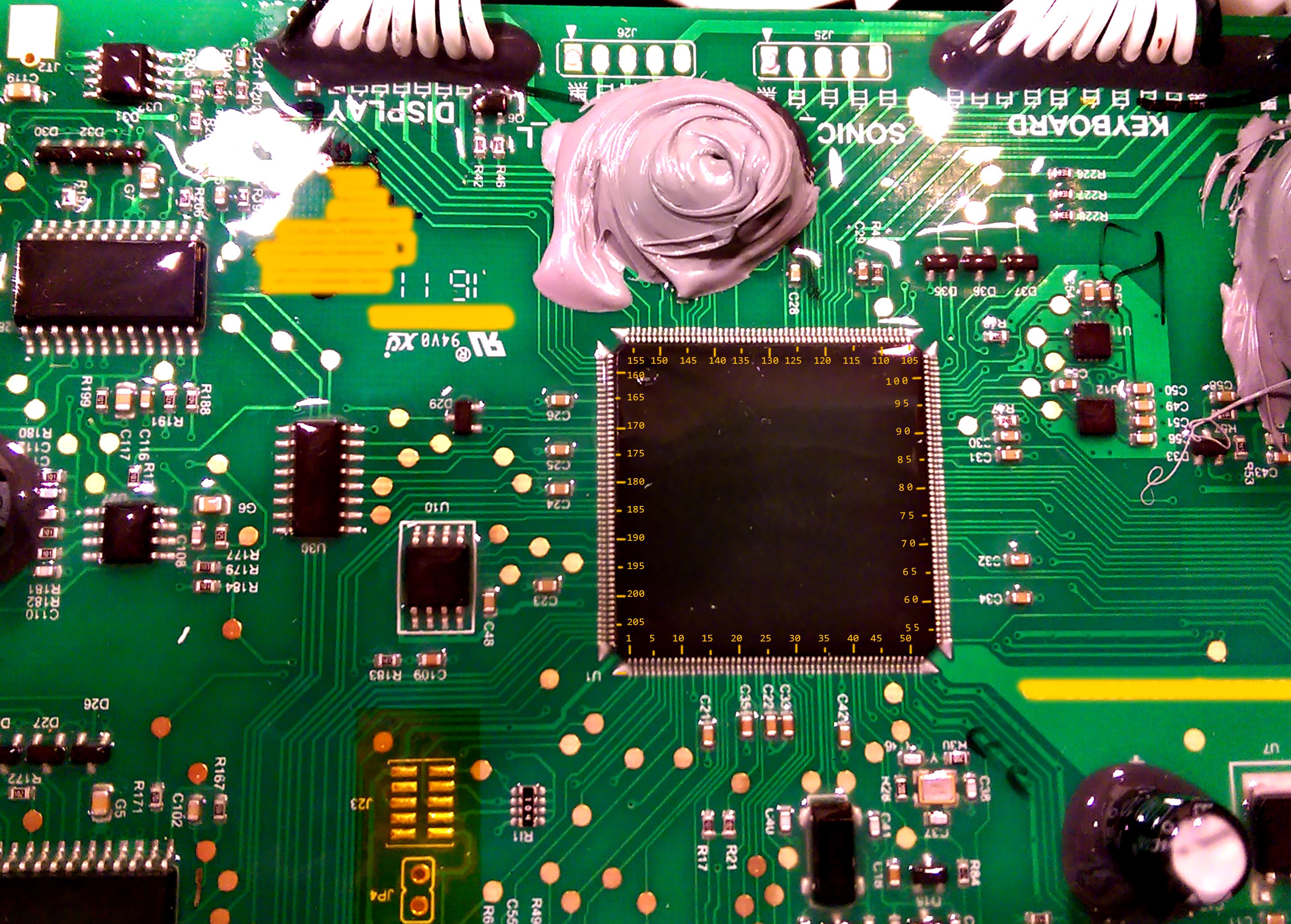
IC's on DB504-03:

The onboard bootloader checks USB after memory stick after firmware file and flashes the its contents.
Custom firmware does not overwrite the bootloader, so it is possible to revert to original firmware.
DB275 firmware start at 0x9000
DB504 firmware start at 0x10000


Source code: https://github.com/Damme/LandLord

To setup build enviroment follow How to install the ARM toolchain
Also possible to use KEIL-MDK.


Please feel free to donate money.
I currently own thrr landdroid's. Two 791e 2015, 794e 2014 - with DB275 motherboard and one wg791e.1 (2016) with DB504.

Bitcoin: 3FnkdzXjkyeHK5o5H3wzM9jDzw52Q3GEog

  • 1 × Brave owner In case the mower starts chasing your pets and begins to burn under your car!
  • 1 × Worx Landroid https://www.worxlandroid.com/
  • 1 × USB stick generic for flashing firmware - FAT32 formatted

  • Working on integratin OpenMower project

    Daniel Wiegert05/15/2022 at 07:55 0 comments

    Hello all, I am getting quite a few PMs about this project.

    I recently started programming again with the goal of making the firmware able to talk to OpenMower. https://github.com/ClemensElflein/OpenMower

    The code on my GitHub is NOT READY YET. At the moment lpc1788 version of the code compiles but not the lpc1768. I am prioritizing LPC1788 at the moment but then that is somewhat ready for use I will start looking at the lpc1768 code again.

    Pinout diagram can be found at https://github.com/Damme/LandLord

    edit; spelling

  • Not the update you all wanted I guess..

    Daniel Wiegert09/28/2021 at 10:51 0 comments

    Hello all!

    First of all, Sorry for not answering you guys at all more or less. Also, I just noticed the link is bad to the io diagram so here is the link again:
    https://drive.google.com/file/d/0B98aBL1DeE4uc3hLQUhHa1FXUGs/view?usp=sharing&resourcekey=0-qmhrLCdqSrvEi-HP7xEJgg

    And the progress? Well there is none. I didn't have energy or time to continue at the time and I also hoped that competition in the market would make the machines better. Not WORSE what I can see they went. So in my eyes the competition only made companies want more profit from existing customers... Sadly.. 
    I also made some progress with DB504 model. I made both 504 & 275 able to move around, start stop mower, start stop charging etc. but this is where I stopped.


    There are techniques to have GPS based navigation down to a few cm position (With RTK gps base station etc)
    I am pretty sure it would be possible to program a simple map only with compass and length meter too, it wouldn't be precise at all but I'm sure basic navigation with this technique would be possible, especially with the modern mcu:s that has a lot of compute power.

    So where am I with this project today?
    I am still interested in developing a new firmware. Especially since no progress have been made at all what I can see in the market..

    Worx still seems pretty cheap and rather easy enough. I don't have any motherboards from the later year models at all. Hopefully they haven't changed much at all but I have no idea.
    So if anyone out there would like to dokument, take hi res photos (Without a potato camera please!) I might be able to cross reference the different models. If I would continue this it would not be very smart to use a soon 8 year old robot for this. but if the motherboards are close enough the code could be somewhat universal.


    Hopefully some of you that are truly interested in this project developing a new firmware are getting this message and maybe we can figure something out together.

    //Daniel

  • Battery

    Daniel Wiegert07/21/2016 at 20:50 3 comments

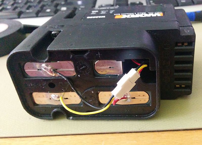
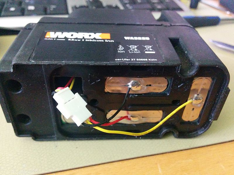
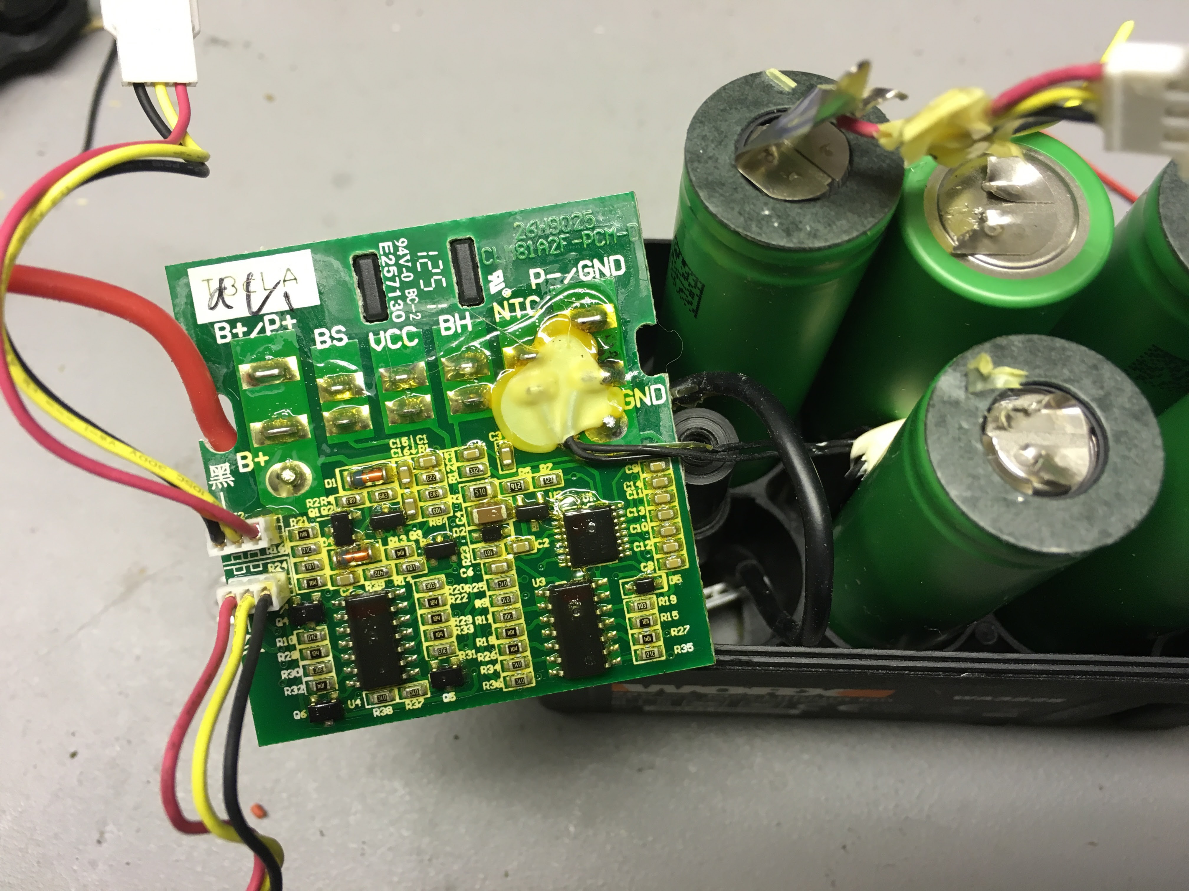
    There have been some discussion over batteries and charging down in the comments. I'll publish images of inside of battery.

    The tabs are solders After case is screwed together. So to split it you need to cut the connecting tabs on one side...

    Cells are Sony 18650 1900mAh. Thanks to Jan B!

  • Unpacker for firmware .pck

    Daniel Wiegert07/19/2016 at 19:09 6 comments

    Warning etc etc, use with caution... Might contain bugs :)

    #!/usr/bin/python3.5
    import sys
    if len(sys.argv) <2:
      print( "usage:" )
      print("  " + sys.argv[0] + " [.PCK file]", "[Folder-prefix]" )
      print( "  " )
      exit()
    import os
    from binascii import crc32
    from struct import unpack
    #get unpack file
    src_file_path = sys.argv[1]
    #read file length
    src_file_size = os.path.getsize(src_file_path)
    #read file
    b = bytearray(open(src_file_path, 'rb').read())
    # crude bytearray to String converter
    def toStr(b):
      return "".join(["%c"%i for i in b]).strip("\x00")
    # convert 4 bytes to int
    def word2int(w):
      return unpack("<I", w)[0]
    # crude filetable parser
    def getHeader(b, datastart):
      beginstart=b.find(63) #"?"
      filename = toStr(b[0:beginstart]).replace("\\","/")
      beginstart+=1
      beginlength=b.find(63,beginstart) #"?"
      start = int(b[beginstart:beginlength],16) + datastart + 4
      beginlength+=1
      length = int(b[beginlength:beginlength+10],16)
      return {
        "filename": filename,
        "start" : start,
        "length" : length,
        }
    #crude way to create nonexisting directories
    def checkCreateDir(filename):
      if not os.path.exists(os.path.dirname(filename)):
        try:
            os.makedirs(os.path.dirname(filename))
        except OSError as exc: # Guard against race condition
            if exc.errno != errno.EEXIST:
                raise
    def save(filename, data):
      checkCreateDir(prefix + "/" + filename) #create missing directories
      print ("writing %s\t (%d bytes)"%(filename,len(data)))
      open(prefix + "/" + filename, 'wb').write(data)
    ## Start decoding
    print("Unknown byte 0:\t"+ str(b[0]))
    print("Unknown byte 1:\t"+ str(b[1]))
    print("Unknown byte 2:\t"+ str(b[2]))
    print("Unknown byte 3:\t"+ str(b[3]))
    prefix = sys.argv[2] if len(sys.argv)>=3 else "."
    headerstart_token = bytearray((int(62), int(0x0d), int(0x0a)))
    headerstart = b.find(headerstart_token,0)+3
    pos=headerstart
    datastart_token = bytearray((int(0x0d), int(0x0a), int(0x0d), int(0x0a)))
    datastart = b.find(datastart_token,0)
    print("header end: \t"+ str(datastart))
    nHeaders = b.count(int(13),4,datastart)
    print("# files \t: "+str(nHeaders))
    # crude way to parse the directory table
    files = []
    print ("found %i files\n"%nHeaders)
    token = bytearray((int(0x0d), int(0x0a)))
    for i in range(nHeaders):
      pos2=b.find(token,pos)
      h = getHeader(b[pos:pos2], datastart)
      files.append(h)
      print(h)
      pos = int(pos2)+2
    for h in files:
      bFile = b[h["start"]:h["start"]+h["length"]]
    #write stripped file
      save(h["filename"],bFile)
    print("Done!")
    

  • Help identifying component (solved)

    Daniel Wiegert07/06/2016 at 08:24 4 comments

    The right one, its a ST L3GD20H, Thanks Ajlitt!


    Left is MMA8452Q, 3-axis, 12-bit/8-bit digital accelerometerhttp://www.nxp.com/files/sensors/doc/data_sheet/MMA8452Q.pdf

  • Pinout DB504

    Daniel Wiegert06/27/2016 at 19:57 3 comments

  • Different motherboards.

    Daniel Wiegert06/20/2016 at 21:16 2 comments

    I've been working on mapping 2016 year model of worx, they use DB504 motherboard. Usually .pck-firmware, its a container and the start is plain-text. It's possible to do a splitter for that but I use dd to copy out the firmware.

    DB504 probably use LPC1788. I've been looking on some io's on a picture I've recieved and it seams to be correct. (not possible to read chip text without removing the conformal coating)

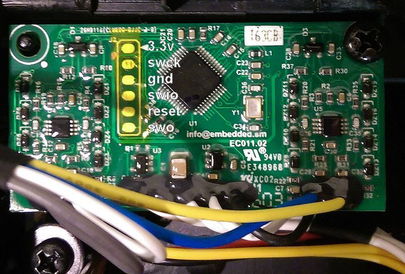
    My guess so far is U10 = spi flash. U11 + U12 compass / accelerometer / gyroscope. Yellow tape protects JTAG from the coating

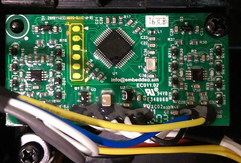
    Display and Keyboard are the same as previous models. Wire sensor uses a daughter board:

    Should we assume they still uses LPC and that this might be an LPC11U6x?

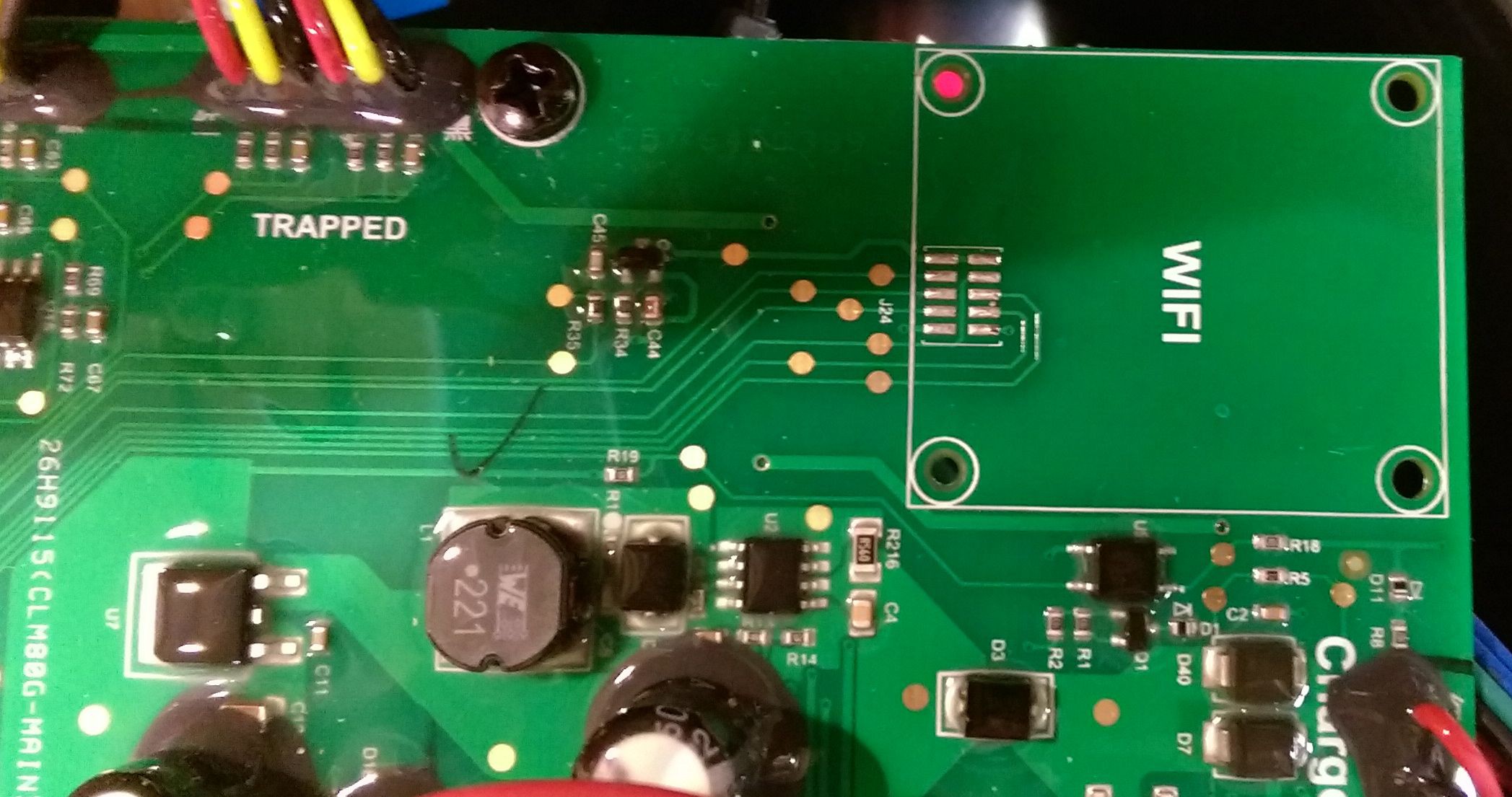
    Wifi module are supplied from http://www.redpinesignals.com/, uses SPI (SSP0) communication. easy to mod! :)

    ( https://www.ghielectronics.com/catalog/product/282 looks like a suspect...)

    So far I've been developing and reversing DB275 (2015 WG790/791/794) It seams all 2016 has DB504.
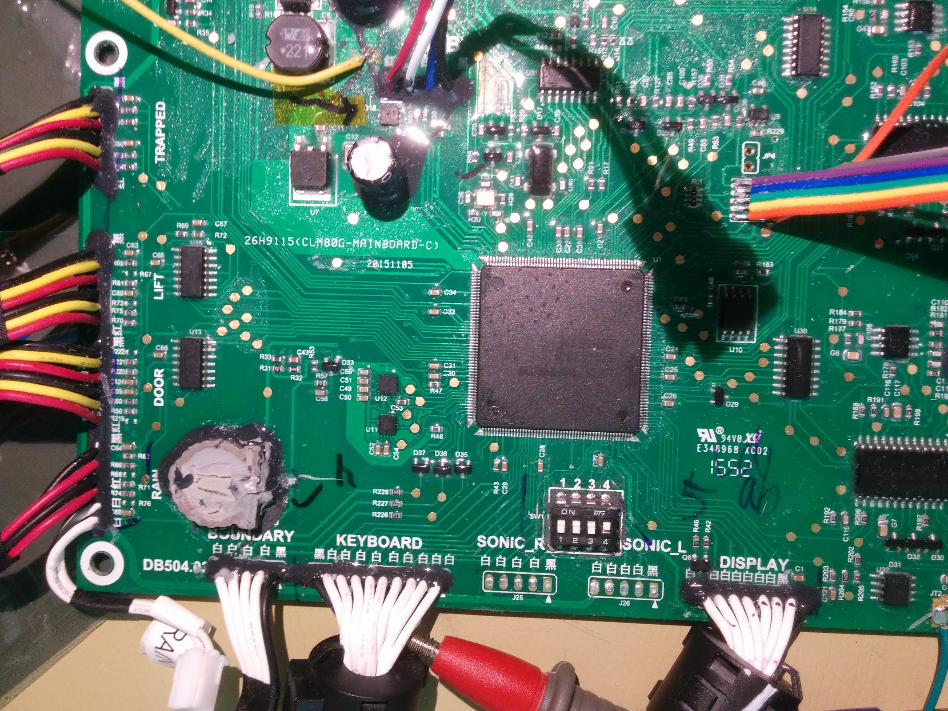
    WG796e (2015) uses DB297 which I haven't seen yet. So if any one wants to send in pictures of that motherboard it would be very appreciated!

    I don't know much about earlier versions.

    //Daniel

    edit:

  • Some / Slow progress

    Daniel Wiegert06/07/2016 at 09:05 2 comments

    I had a small break, I let the mowers do their job outside! :)

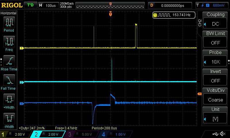
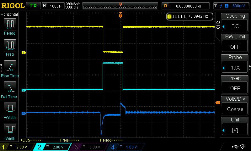
    I've figured out the boundary wire and how it works. I finally got the idea to use the USB d+ and d- (p0.29 + p0.30) and output of p0.7 - p0.10 and measure with oscilloscope.. :) (4 wire inputs -> raising and falling each on pos / neg)

    The blue is probe directly on the boundary wire.

    So if negative measurement is before or after the positive, then you know if you are inside or outside wire.

    p0.21 select amplification or something, you can detect if you are within 1 meter of the wire or not.

    p0.22 probably selects between left and right sensor.

    And if you are close to the sensors you get some weird artifacts in the measurement, longer pulse, and even more than one pulse. It seams this is following a pattern and it might be possible to user and detect the distance to the wire at 0cm, 10cm, 20cm and 100cm.

    And the last one, wire right on top of the sensor.

  • Original firmware?

    Daniel Wiegert05/06/2016 at 12:32 4 comments

    I could use some owners help. I would like to have your firmware-files!
    I need to see how big of a difference it is between models.

    Please contact me!

    Thanks all!

  • Pinout!

    Daniel Wiegert05/03/2016 at 08:14 0 comments

    95% of the pin-out is finished. There are some questions still to be answered. Also the models with WIFI, How do they look inside? I would love to see some pictures of the main board in that one!

    One guess would be that the un-populated IC nead RTC battery is a SPI flash but not confirmed.

    Next important step would be to understand the how the wire sensor works.

    P0.0  GPIO Output, Motor Left, Select Forward/Reverse
    P0.1  GPIO Input, Dip switch 3
    P0.2  ADC6, Motor Right, Current ?? -> Need more investigation
    P0.3  ADC7, Motor Left, Current ?? -> Need more investigation
    P0.4 + P0.5 GPIO Output, Selector ADC4 input -> accelerometer LIS352AR pin S0, S1.
      0    0 - ADC4 = X
      0    1 - ADC4 = Y
      1    0 - ADC4 = Z
      1    1 - ADC4 = aux (temp batt)
    P0.6  GPIO Output, Speaker High volume
    P0.7  GPIO Input, ExtInt3 Raising edge - Wire sensor -> Need more investigation
    P0.8  GPIO Input, ExtInt3 Falling edge - Wire sensor -> Need more investigation
    P0.9  GPIO Input, ExtInt3 Raising edge - Wire sensor -> Need more investigation
    P0.10 GPIO Input, ExtInt3 Falling edge - Wire sensor -> Need more investigation
    P0.11 GPIO Output, Enable Charging (in charger, after P1.23 is set to 1)
    P0.15 SPI SCLK, LCD
    P0.16 SPI CSB, LCD
    P0.17 SPI MISO, LCD <- Unused? NC?
    P0.18 SPI SDA, LCD
    P0.19 SPI RSTB, LCD
    P0.20 SPI A0, LCD
    P0.21 GPIO OUTPUT, Selector Guide Wire sensor, Range / Amplification
    P0.22 GPIO OUTPUT, Selector Guide Wire sensor, Unknown function -> Need more investigation
    P0.23 ADC0, Charge current? (Or Charge voltage, Only >0 then charging) 
    P0.24 ADC1, Voltage Battery
    P0.25 ADC2, Accelerometer, Sideways (X/Y)
    P0.26 ADC3, Accelerometer, Forward (X/Y)
    P0.27 GPIO Input, Motor Rotor, Rotation tick? -> Need more investigation
    P0.28 GPIO Input, Charger state? Battery full? -> Need more investigation
    P0.29 USB D+, Maybe used for softUART for GPS / External mcu communication
    P0.30 USB D-, Maybe used for softUART for GPS / External mcu communication
    
    P1.0  GPIO Input/Output, Keypad matrix Row1
    P1.1  GPIO Input/Output, Keypad matrix Row2
    P1.4  GPIO Input/Output, Keypad matrix Row3
    P1.8  GPIO Input/Output, Keypad matrix Row4
    P1.9  GPIO Input/Output, Keypad matrix Col1
    P1.10 GPIO Input/Output, Keypad matrix Col2
    P1.14 GPIO Input/Output, Keypad matrix Col3
    P1.15 GPIO Input/Output, Keypad matrix Col4
    P1.16 GPIO Input, Hall Sensor, Lifted
    P1.17 GPIO Input, STOP Button
    P1.18 Unknown, NC?
    P1.19 Unknown, NC?
    P1.20 GPIO Output, LCD Backlight ON, PWM1.2 can be used here if motors are inactive. (Pulsing screen then charging)
    P1.21 GPIO Input, High then connected to charger and charger is RED
    P1.22 Unknown, NC? USB Power on??
    P1.23 GPIO Output, Initiate Charger, Keeps charger in RED mode. if low charger shows green light.
    P1.24 GPIO Output, Speaker Low volume
    P1.25 GPIO Output, Keep high for PCB Power on.
    P1.26 Unknown, NC? Sensor?
    P1.27 Unknown, NC? Sensor?
    P1.28 GPIO Input, Power key, Normal HIGH
    P1.29 GPIO Input, Sensor, Rain
    P1.30 ADC4, Output from LIS352AR, Selected by P0.4 + P0.5
    P1.31 ADC5, Motor Rotor, Current ?? -> Need more investigation
    
    P2.0  PWM1.1, Motor Right speed
    P2.1  PWM1.2, Motor Left speed
    P2.2  PWM1.3, Motor Rotor speed
    P2.3  GPIO Input, Dip switch 2
    P2.4  GPIO Output, Motor Right, Enable/Start | Disable
    P2.5  GPIO Output, Motor Right, Brake ON/OFF
    P2.6  GPIO Output, Motor Right, Select Forward/Reverse
    P2.7  GPIO Input, Dip switch 3
    P2.8  GPIO Output, Motor Left, Brake ON/OFF
    P2.9  GPIO Output, Motor Left, Enable/Start | Disable
    P2.10 GPIO Input, EInt0??, Sens Motor? Error?  -> Need more investigation
    P2.11 GPIO Input, EInt1 Edge, Motor Right Rotation tick
    P2.12 GPIO Input, EInt2 Edge, Motor Left Rotation tick
    P2.13 GPIO Output, Motor Rotor, Enable/Start | Disable
    
    P3.25 GPIO Output, Motor Rotor, Brake ON/OFF
    P3.26 GPIO Output, Motor Rotor, Select Forward/Reverse
    
    P4.28 GPIO Input, Hall Sensor, Cover
    P4.29 GPIO Input, Hall Sensor, Front

View all 21 project logs

Enjoy this project?

Share

Discussions

ms1 wrote 09/14/2024 at 18:27 point

I am interested in making an open source software for the WG79x-models. Is there somewhere we can discuss wg79x reverse engineering? I tried the discord channel mentioned in github readme, but it does not seem to be active anymore?

  Are you sure? yes | no

Andreas Ericsson wrote 09/10/2024 at 09:53 point

Hi,

I just wanted to document my findings when measuring the output signal to the boundary wire from the charging station of my Works Landroid M WG790E.1 with an oscilloscope:

The signal is a continous repeated pulse with 119us width and it is repeated with a period of 13.07ms (76.5Hz). I measured the amplitude to 7.3V using 1.8Ohms as wire resistance so the peak current is ~4A. It should be fairly straight forward to implement a signal generator using a simple MCU and a FET to replace the circuit board in the charging station.

  Are you sure? yes | no

maag.dominic wrote 07/07/2024 at 08:39 point

Hi,

I also found this cause I was looking for new features for my Worx Landroid WR147E.1. Looks like all the efforts are going into the new Vision model. I started getting deep rutmarks from the robot's wheels slipping and digging in. So I thought to myself would be awesome if the sensitivity or behavior could be changed as well as new features added to the robots firmware as well as app. For example in the app would be nice if you could see when it's supposed to mow with the countdown timer. The robot, it would be awesome if it could spotmow when I move our kids garden toys and also choose between systematic and random mowing mode, same as Bosch Indego does. Especially the spotmow should not be so difficult. Or enable it to be remote controlled by the phone as with the vacuum robots. Would be awesome if someone would add these features as it seems Worx stopped everything on the now older models when I asked them about app improvements. If I had the knowhow I would tinker with it myself. 

  Are you sure? yes | no

RichM wrote 10/10/2023 at 08:28 point

Just stumbled on this project after looking at openmower. I have a WR141E with no accessories at the moment other than a lump of stainless steel on the back end to help with traction. I'm fed up watching this stupid mower get stuck in my garden and hope to improve it. Winter season is nearly here so I'll be tearing it down and looking at the guts in detail in the hope that I can reprogramme it or give it a brain transplant with help from this project. I don't think I need RTK GPS (because that seems like its an expensive option) but I do need it to respond sensibly to the wire and situations where it bumps into things.  Whatever I do it needs to be as far as possible nondestructive to the original mower because if it all goes wrong I'll still need it next season. I'll post updates/photos once I get started.

  Are you sure? yes | no

Not my name wrote 08/29/2023 at 06:04 point

I have worx wg790, anyone who can help me get a method get a PIN I can pay 100$. email me  jparadnikas at gmail

  Are you sure? yes | no

caerts wrote 06/25/2022 at 09:41 point

Hi, Thank you for this beautiful project. How should I try it on may WG793 ? How to generate BIN or PCK file from git clone ? Best regards

  Are you sure? yes | no

Sancho_sk wrote 08/24/2021 at 16:00 point

Hi, all. Nice work. I am looking into this and it's really interesting. From my perspective, I am satisfied with the firmware, I would just like to avoid the "official app".  Did anyone had any luck with reverse engineering the ESP32 firmware and the communication protocol?
Or, perhaps, just reflashing the ESP with something I can write as long as there is a known communication way between the ESP and the main MCU?

  Are you sure? yes | no

Tomo wrote 07/09/2021 at 22:29 point

Hi, nice work so far! 

STEP 1: I would like to try the firmware on my WG794E but I have to admit that I'm not so familiar with the steps needed in order to get it on a USB drive. I saved all the files from github (provided link) but I couldn't find any info on how should it be done.

STEP 2: I will try to dump the original firmware of my WG794E...

Maybe I should swap the steps :)

Many Thanks

Tomo

PS Forgot my PIN and now it is useless (a challenge to have it rebuilt on Arduino)

  Are you sure? yes | no

Lennaert Tolhoek wrote 05/26/2021 at 15:34 point

Hello, I'm the owner of a Worx Landroid L2000i. I want my mower to mow 160 hours a week. The default firmware (i think) is limited to 2000m2 and 40 hours a week. While, if the machine could work 24/7, in theory would be able to do 8000m2. Which is what I need. Who can help me to alter the firmware?

Regards,

Lennaert

  Are you sure? yes | no

SzigetiD wrote 05/20/2021 at 22:07 point

Hello

Can anyone help me with the frequency and voltage of the boundary wires?
Can anyone measure it?

Thanks, David

  Are you sure? yes | no

Andreas Ericsson wrote 09/17/2024 at 12:45 point

The signal is a continous repeated pulse with 119us width and it is repeated with a period of 13.07ms (76.5Hz). I measured the amplitude to 7.3V using 1.8Ohms as wire resistance so the peak current is ~4A. 

  Are you sure? yes | no

thomywb wrote 08/06/2020 at 19:53 point

Hello,

i have a WG 795. my Rainsensor error A10 . How i reset the error? How i test the rainsensor ?

It is possible break the wire to the rainsensor?

Thomas

  Are you sure? yes | no

Ddudu wrote 06/29/2020 at 20:28 point

hello! i got one WG 790 e.1 that i got from a friend, and he forgot the code on it. is there any way to remove the code? or reset?

  Are you sure? yes | no

ESP4Ever wrote 11/17/2021 at 09:24 point

Hi!

If you familiar with Arduino programming you can easily bruteforce it.

I brought a brand new-looking WG790E from a recycle center (looks like the owner forgot the PIN too and just scrapped the robot) and with help of Arduino Due found the PIN in few hours :) The only problem was that PIN can be 1 - 4 digits long, with or without leading zeros if less than 4.

  Are you sure? yes | no

emil.gudmundsson wrote 08/10/2022 at 12:06 point

You don't happen to have the code saved?
Am pretty much in the exact same situation but without any real Arduino knowledge.

  Are you sure? yes | no

Isak Johansson wrote 05/18/2020 at 10:56 point

Hi! I got a Worx Landroid WG790E.1 with possibly a DB504 board. Im wondering if anyone can tell me how to reset it manually with the JP4 thing or "reset pin". I only know gaming boards :/. I'll help in any way i can to return the favor.

Kind regards 

Isak ^.^

  Are you sure? yes | no

danielfaxcopy wrote 05/15/2020 at 06:28 point

Hi Friends,

Could you help me, what type exactly Motor Drive IC - there is 3 pieces  - i found Q10 dead  :-(


Thanks for all!


  Are you sure? yes | no

er_toma wrote 05/01/2020 at 06:58 point

Hi, I have Landroid L WG79X with board DB275-9, firmware V0.50. how can I read the log file?

or there is a software to connect the robot?

Thank you

  Are you sure? yes | no

fracii wrote 04/19/2020 at 21:47 point

Hi, I have al-ko robolinho 700 and get crazy over angel/level sensor limit. Its a magnetic chip with 6 wires and a magnet. Working for all directions and work also as bumper and lifting sensor. Anyone know How I can bypass this so I can go greater 45%. Thinking to hack the firmware but it's ASCII.hex.. In service software maximum is set for the program limit for resellers 30 degree..

  Are you sure? yes | no

popz3210 wrote 04/13/2020 at 14:18 point

Has anyone been able to add a WiFi card to the US version?

  Are you sure? yes | no

Niedved wrote 10/17/2019 at 17:16 point

Hi. I bought damaged Worx Landroid WG 797E.1 2016 as a base for my Robo Project :) luckly I was able to fix Base and few more elements inside machine and all start YEAH. Unfortunately Worx was locked with PIN and there is no contact to seller.

If I want to instal this open source firmware is it possible with PIN on it ? Or maybe there is another way to make hard reset to launch original soft to test it before instaling new firmware ?

Cheers 

  Are you sure? yes | no

hans hult wrote 08/05/2019 at 09:16 point

Hi 
Got an WG790e1 that i will start play with . 

Do i need an Jtag adaptor or are there any drivers to use for direct connection to my pc ? 

// Hans 

  Are you sure? yes | no

Riley wrote 06/13/2019 at 04:24 point

Just got one of these on a pretty good deal for an open box but unused. Want to start hacking on it but so far have hit a snag on normal operation. Clock time resets if the unit turns off. Super annoying but is making me wonder if this Landroid has a bad controller. Any idea if there is a internal battery on the main control board or if I should be investigating the main battery. 

  Are you sure? yes | no

Similar Projects

Does this project spark your interest?

Become a member to follow this project and never miss any updates