-
327 35AR?
05/02/2016 at 16:03 • 0 commentsI think I've solved the mystery!
Not exacly the same, but I would guess its very similar to this LIS352ARhttp://www.farnell.com/datasheets/1698882.pdf
Package is the same, same 3 analog outputs.
-
Guide Wire...
05/02/2016 at 11:59 • 0 commentsI am trying to figure out how the guide wire sensors work.
There are 4 inputs (digital), P0.7, P0.8, 0.9, P0.10) that the original firmware has put on extint3, two trigger on Falling edge, the other two on Raising edge. Probably and each on each sensor.
There are also two control pins (digital).
One is for Range, or Amplification, P0.21.
If I'm close I get triggers regardless of p0.21 state, and then I am far away from guide wire I only get triggers then P0.21 is High.The other control pin is so far unknown, P0.22. It changes the output on P0.7-0.10. I cannot figure out how this works yet.
The Falling edge's also show if the mower is looking perpendicular to the guide wire; P0.8, P0.10 is high.
If the mower looks 'Downrange', P0.10 is high, P0.8 low.
If the mower looks 'forward', the opposite, P0.8 High, P0.10 Low.So, any suggestions? My next move is probobly to try to make a logfile of all the triggers, there are around 10-20 per second.
-
Finally!
04/28/2016 at 18:47 • 1 commentYes, Finally I have reverse engineered enough for a source release.
**** THIS IS NOT A REPLACEMENT FIRMWARE!! ****
Its not working in a long way. it needs _ALOT_ of work!
This firmware is designed for WG791 (Other models may be compatible with small changes)
The firmware can be put on a USB (as "DB275_GRAF.bin" ) and be flashed with the original bootloader. This firmware keeps the original bootloader so it is possible to restore original firmware.This firmware does not brick my mower. But, It might brick yours!
I don't take any responsibility but I will help you try to fix it. It would REALLY be a good idea and backup the original firmware fist ( the firmware-file from worx does not include bootloader! )The code Really needs a lot of work, it is just a proof of concept.
https://github.com/Damme/LandLord
If you are brave enough to flash it, and want to try the motors out, please remove the cutting blades first.
After entering one of the menu's, press 'start' to initiate all settings, pwm, gpio etc.
keys as follows:
1: Start/Stop
2: Brake on/off
3: Forward / Reverse
Debug IO prints all IO, you should see changes if you close/opens the lid for example.Please let me know if you want to help!
-
Small update
04/20/2016 at 22:12 • 1 commentI have gotten a few messages about this project, if it dead etc. No! It is still alive!
There will soon be a rather big update of code that can control all motors and sensors on the mower.
//Damme
-
Progress - FreeRTOS and keypad.
11/10/2015 at 18:59 • 0 commentsI've choosen FreeRTOS Real Time OS as base for this project. I think it will do good with it task-management and priorities. Anyone who has any comments about this?
I've also managed to figure out the keypad and how the power button works. I have also reversed engineered a lot of pin's that goes to the motor controllers. I havn't looked at any ADC-ports yet. I dont know how battery charging works neither.
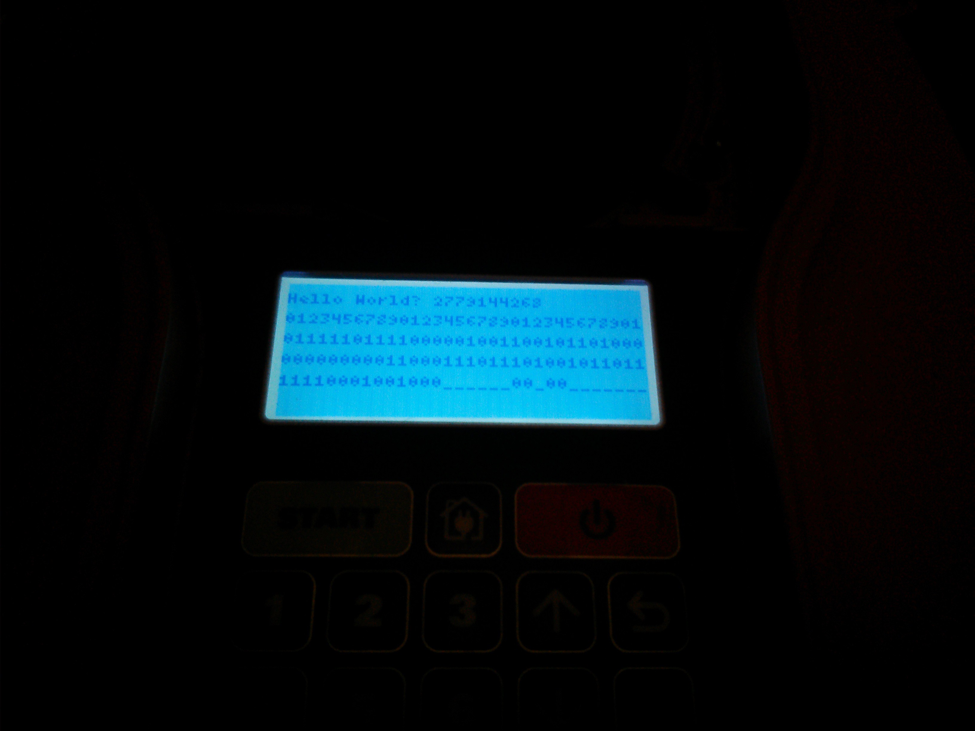
Sorry for dark image, but my phone camera doesn't work very well. It is debug of gpio on the device. This demo runs FreeRTOS.
![]()
//Damme
-
Hello World - Source
11/06/2015 at 21:58 • 0 commentsSourcecode for hello-world: github.com
-
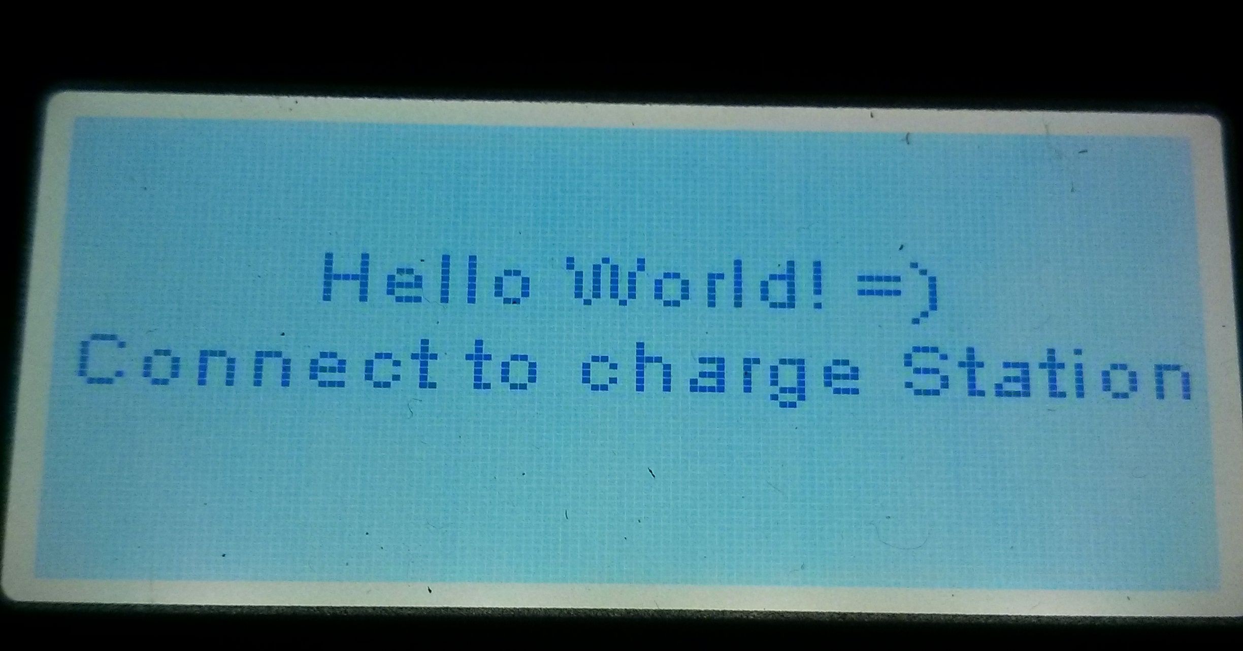
Hello World! For real!
11/03/2015 at 16:53 • 0 comments![]()
Using u8glib, scrolling Hello World!
-
More reverse engineering
11/01/2015 at 14:18 • 0 commentsI managed to loosen the LCD from the front, it was glued but I won the battle!
Found a sticker saying "LINK wo12864-tgh#" and some searching gave me the following results:
Manufacturer of module : http://link-lcd.com/
Manufacturer of LCD with cog : http://www.newhavendisplay.com/specs/NHD-C12864WO-B1TGH-M.pdf
and this library would probably work: https://github.com/olikraus/u8glib
I've also made some progress probing the pinout of the main processor: robot.pdf (*Updated link, now works)
I also noticed that the IC I believed was a RTC module is probobly a 3.3v li ion charge module of some sort. Haven't found any data on it yet. It's marked with '327 35AR'
Next thing would be to do some programming.. :)
Please feel free to join my project!
-
Bricked and unbricked! :)
10/30/2015 at 11:11 • 0 commentsYes, I managed to brick my landroid. I even got a bit worried before I managed to unbrick it again. And while unbricking it via jtag/swd I made a simple modification to please the programming god!
![]()
This is just a proof of concept that I managed to unbrick and flashed my modified firmware via openOCD.
The next step would be to do a REAL 'Hello World', but for this I have to identify the unknown 128x64 chip-on-glass display.
I tried to dismantle but the pieces seams glued stuck and I don't want to break anything. So I'll search around and see if there are any standards how to speak to the display.
It talks via SPI and uses 8 pins.
- * K
- * CSB
- * A0
- * SCLK
- * SDA
- * VDD
- * GND
I also noticed I missed to identify an IC, probobly an RTC (Real Time Clock) type of chip:
I can't find anything on this, so if anyone has better luck please let me know!
![]()
-
Finally started up the project once again!
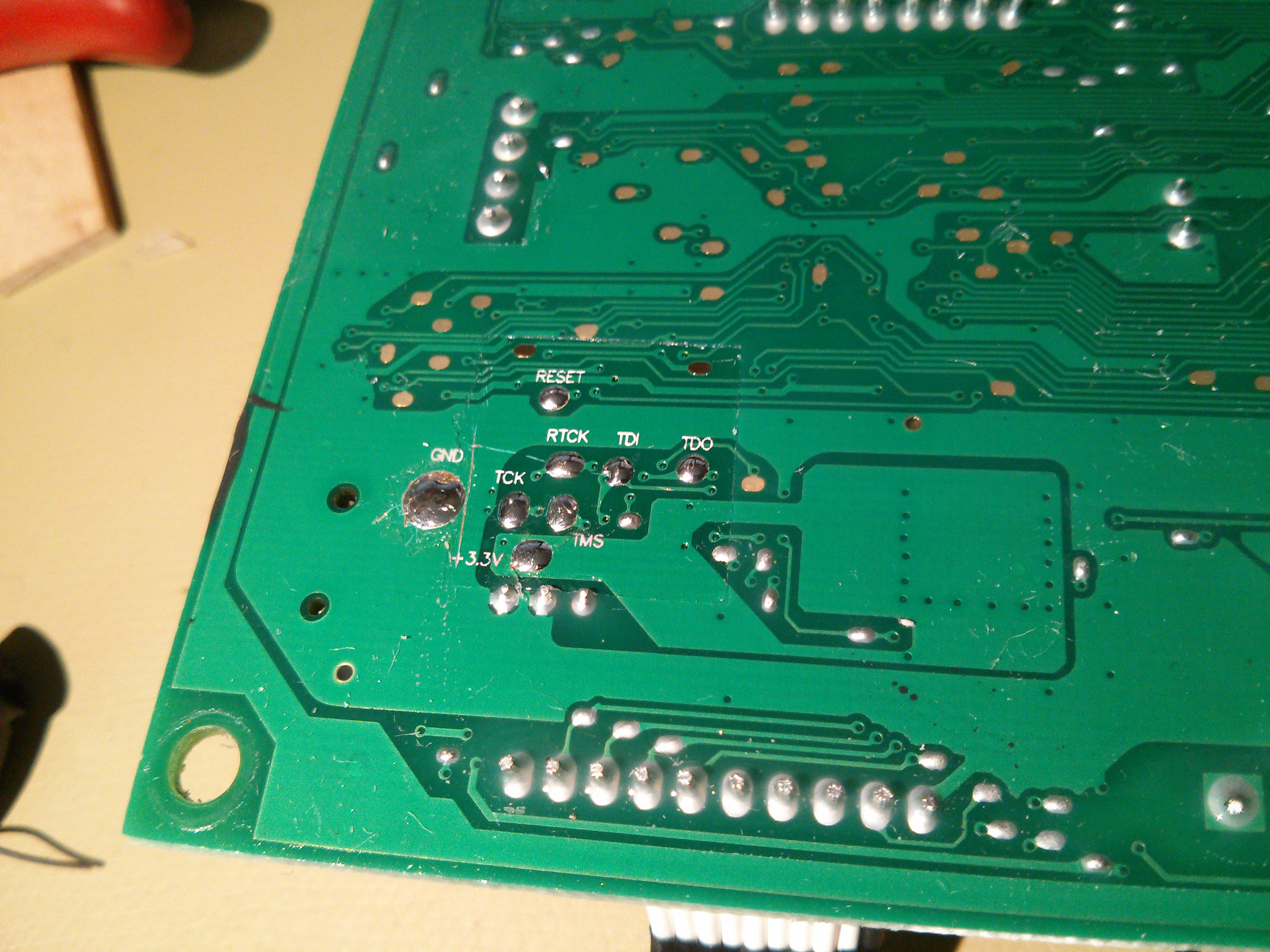
10/28/2015 at 16:05 • 0 commentsI found a JTAG on the bottom of the PCB, been dumping with a st-link v2 module.
![Pinout on bottom of PCB]()
To connect to ST-Link v2:
ST-link V2 JTAG on worx reset RST swdio TMS swim TDO swclk TCK 3.3v +3.3v GND GND I've used OpenOCD to dump data. I do have an updates lpc1768.cfg target that I will put on github. But it is possible to connect with openocd 0.9.0 direcly also:
openocd -f interface/stlink-v2.cfg -c "transport select hla_swd" -f target/lpc17xx.cfgHere is a list of hardware on the PCB:
- 3x3 FDD8424H 40V Dual N & P-Channel PowerTrench® MOSFET -> https://www.fairchildsemi.com/products/discretes/fets/mosfets/FDD8424H.html
- 3x MC33039 Closed Loop Brushless Motor -> Adapter http://www.onsemi.com/pub_link/Collateral/MC33039-D.PDF
- 3x mc33035dw Brushless DC Motor Controller -> http://www.onsemi.com/pub_link/Collateral/MC33035-D.PDF
- 2x unl2003a ULN200x, ULQ200x High-Voltage, High-Current Darlington Transistor Arrays -> http://www.ti.com/lit/ds/symlink/uln2003a.pdf
- 2x lm2904 Dual Operational Amplifiers -> http://www.ti.com/lit/ds/symlink/lm158.pdf
- 33063 MC3x063A 1.5-A Peak Boost/Buck/Inverting Switching Regulators -> http://www.ti.com/lit/ds/symlink/mc33063a.pdf
- lm238 THREE-TERMINAL 5-A ADJUSTABLE VOLTAGE REGULATORS
- lm239 Quad Differential Comparators -> http://www.ti.com/lit/ds/symlink/lm139.pdf
- 2x irf fr5305 -> http://www.irf.com/product-info/datasheets/data/irfr5305.pdf
- lm2904 Dual Operational Amplifiers -> http://www.ti.com/lit/ds/symlink/lm158.pdf
- cd4066bm CMOS QUAD BILATERAL SWITCH -> http://www.ti.com/lit/ds/symlink/cd4066b.pdf
- mic4680 1A 200khz superswitcher buck regulator -> http://www.micrel.com/_PDF/mic4680.pdf
If you find this intresting and think you might be able to assist - Please message me and I'll add you to the group!
//Damme
 Daniel Wiegert


