zittware
-
Texas Pinball Fesitival - Money Shots
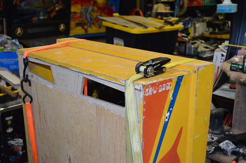
04/09/2014 at 05:50 • 0 commentsHere are some money shots of the machine running at Texas Pinball festival on March 27-30, 2014:
![]() Steve Richie playing the machine:
Steve Richie playing the machine:![]() Here's a picture of the game being played at TPF'14:
Here's a picture of the game being played at TPF'14:
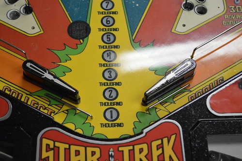
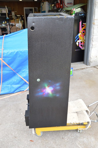
https://www.youtube.com/watch?v=zhvaot9xbjICloseup of the nixie tube display:
![]()
ShawnC snapped a few pictures from TPF and posted them to FB with me tagged; Passing them along:
![]()
![]()
![]()
Are you going to the Austin Mini-Maker Faire on May 3rd, 2014? If so look me up; the Mirror Universe Pin will be present at that festival.
-
Finishing Touches
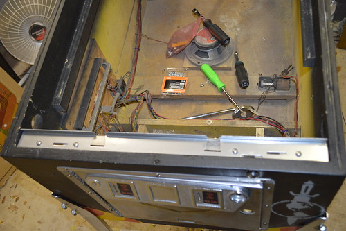
04/09/2014 at 05:41 • 0 comments3/13/2014: Been spending the last few nights chasing the bugs out of the system. Got the MPU board to boot, but goes straight into diag mode instead of attract mode.
Had a Solenoid board with a bad 'LS154 decoder. The ChipSelect pin was shorted to ground; causing the coils to fire every time the soundboard was accessed. It was pretty funny to hear the star trek theme being beat out by coils on the PF.
Tonight I worked on some of the lamps and began reassembly of the coin door.
Since that's all I have to report; let's take a step back in time and continue updates from this past weekend.
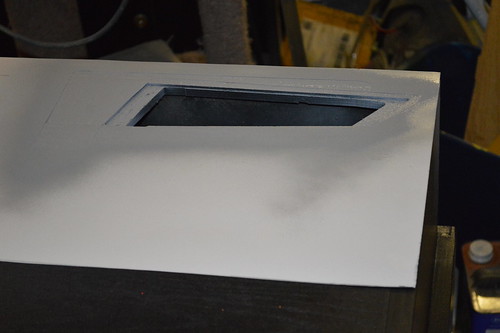
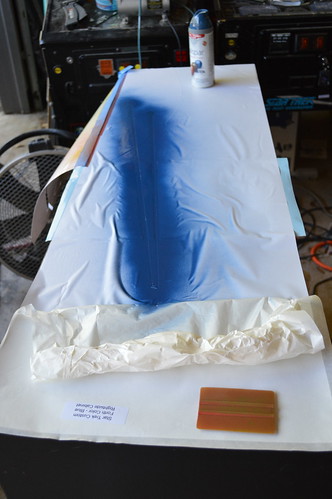
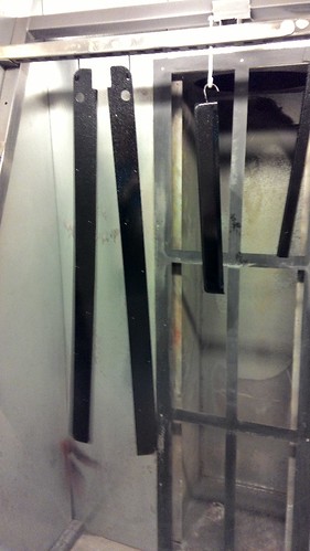
The Plastics were installed given the ball guides were completed. One of the pet peeve areas of the original Bally is the darkness of the Enterprise plastic behind the drop targets. Given the entire machine is planned to be LED for it's entire life; I don't have to worry about lamp heat melting the posts. So; drilled a hole between the two posts:![]()
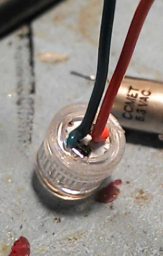
I promptly voided the warranty of one of Comet Pinball's LEDs by removing the Bayonet Base and collar... then soldered a Green and Orange GI wire to the diodes.![]() I saved the 30ohm current limit resistor from the base and soldered inline under the PF:
I saved the 30ohm current limit resistor from the base and soldered inline under the PF:![]() Connecting the wires to the base of a GI lamp socket nearby.
Connecting the wires to the base of a GI lamp socket nearby.
The result:![]() 3/15/2014: Today was a good day... in short; Star Trek: The Mirror Universe LIVES.
3/15/2014: Today was a good day... in short; Star Trek: The Mirror Universe LIVES.
A design short-sight with the MOSFET LAMP board I designed rendered the LED switched inserts too dim. Basically; I had forgotten that the MPU scans each LAMP in sequence which in effect cause the LEDs to be on for only a short period of time. I can't fix the design (will require a board spin at a minimum) in time for TPF; so I had to go back to the original lamp board... along with shoehorn in a 6.3V Switch GI transformer from radioshack.
ShertzPinball loaned me a untested Lamp board which I debugged and was able to get the lamps functioning well enough for TPF. Thanks Jason!
All but one lamp is working... the outlier is the 10K bonus section on the primary hull of the ISS Enterprise. I'm planning on further debug after I get it buttoned together. I suspect a bad SCR; but will have to test.
MPU was going straight into Diagnostics... or resetting after the machine entered Attract mode. given it was going into Diag / test mode was a clue... turns out that the 6821 PIA at U10 had pin 40 bent under the package instead of into the socket. This caused the flakiness.
All solenoids are firing under test; ball ejects into the shooter lane.
All switches adjusted so switch test passes. Original soundcard passes tone test.
Proximity sensors tested and verified working.
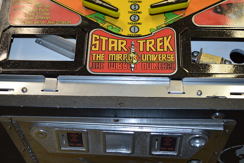
3 of 5 displays are installed in Pl1,2, and the credit window. All pass the diagnostic digit count.
Coin door reassembled and attached to cabinet. Lockdown bar hardware is being cleaned and prepped for re-install tomorrow.
Hope to install side rails and misc cabinet hardware tomorrow.
Sunday I hope to finish the last two displays and install them. It's at this point I'll probably drill the hole for the left handed shooter.
So; What Do I have to report? Let's finish up the picture bomb from last weekend's work. Rather than post a bunch of individual plastics images... I've created a panoramic stitch of several high resolution shots. Feel free to click the picture/link and look at the detailed original image: ( yeah... it's HUGE... so big it wouldn't load in IE11. Chrome or FireFox)![]()
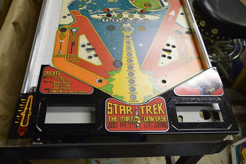
Each plastic (except the orbits) has it's own protector. There is protective transfer tape over the backglass... which will stay on until TPF to reduce scratches.3/17/2014: Attention moves to the Lockdown bar mechanisms and coin door. I resurfaced the coindoor skin with some sandpaper and installed the new coin door inserts; pictures later when I take them. Installed the coin door and proceed to clean the lockdown bar assembly:
![]() I disassembled it and cleaned the rust / grime off with some coarse sandpaper. Once I had the bracket rust free; I powdercoated it with some chrome powdercoat; keeping the metal on metal area free of powder coat. I reassembled the mechanism with stainless steel hardware to help prevent future rust:
I disassembled it and cleaned the rust / grime off with some coarse sandpaper. Once I had the bracket rust free; I powdercoated it with some chrome powdercoat; keeping the metal on metal area free of powder coat. I reassembled the mechanism with stainless steel hardware to help prevent future rust:![]() Playfield hanger bracket got the same sanding/powdercoating treatment:
Playfield hanger bracket got the same sanding/powdercoating treatment:![]()
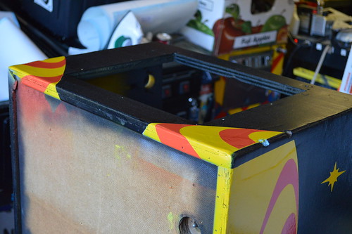
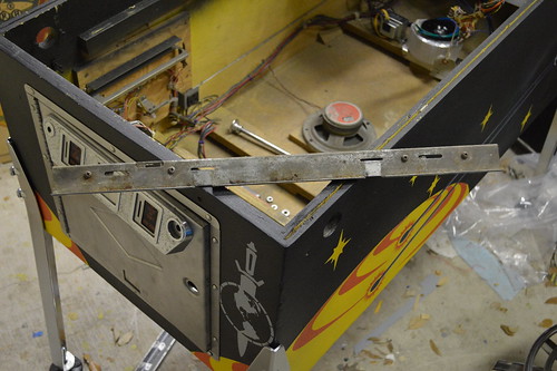
3/18/2014: Time to finish the lockdown bar... but the lockdown bar and side rails kinda go together.
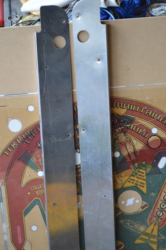
I had bought a new set of side rails from PBResource... but they don't fit right. Not sure if it was my error or theirs. I'll have to email them when I get a chance.
Since I couldn't use the NEW side rails; I really had no choice but to recycle the old ones since I had no time to really source and ship new ones. The old ones were bent by the backbox as some point... and there is a really nasty scratch on one side.![]() I tried resurfacing the rails with a belt sander... but it still looked like as$ to be honest. So... what to do?!?
I tried resurfacing the rails with a belt sander... but it still looked like as$ to be honest. So... what to do?!?
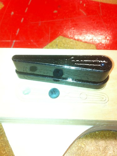
Guess one must powdercoat them with black and the holographic clear coat as was done on the apron.So at 7:30pm Sunday; I jumped in the truck and raced up north to Techshop where I could bake these huge as pieces...![]() Yeap; that's right... I made the lockdown bar match... would you expect any different? I thought maybe the black would be too much; but it's really kinda kick ass on the machine:
Yeap; that's right... I made the lockdown bar match... would you expect any different? I thought maybe the black would be too much; but it's really kinda kick ass on the machine:![]() You likey?
You likey?![]()
-
Power SubSystem
04/09/2014 at 05:31 • 0 comments
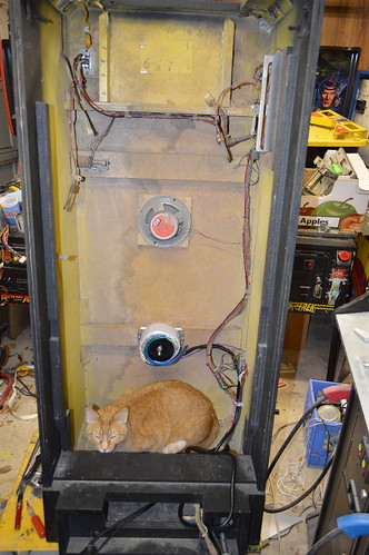
3/6/2014: Work continues on the Transformer and power situation. I began by sleeving the transformer connections to make them less of a mess inside the cabinet and then began wiring the ATX powersupply cable. I thought... hey; I'll just wired the ATX PSU into the existing wiring harness going into the machine. Keep in mind I designed the ATX PSU board to always power the ATX PSU when AC is supplied. So in effect right now; the Machine will always be powered.
The switch in the machine is AFTER where I tied in the ATX PSU - as the Noise Suppressor is only rated for 5Amps as is the cable feeding the main power switch. The switch goes after the noise suppressor. The existing switch is only rated for 5A... and ATXs can demand 15A on a fully loaded machine. So it's not as simple as just wiring the ATX psu after the switch. Gonna have to replace the switch and probably run a wire back to the ATX power cable.
So I took a trip to Lowes to get some 14gauge black wire to wire the hot side from the switch to the ATX power cable. I also stopped by Fry's Electronics to get a suitable switch which could handle the current. I ended up selecting a DPDT 20A / 125V... not because I needed 20A... but because they didn't have anything on the shelf > 10A.
I desoldered the old switch and replace it with the new... putting in a red and a black wire to tie in the ATX PSU. In effect; I've bypassed the noise suppressor on the hot rail. But alas; can't be helped right now as I'm out of time for TPF.![]()
Here's the transformer wired up with sleeved power connections going into the backbox.![]() Overall:
Overall:![]() He is Stinker... and He approves this message!
He is Stinker... and He approves this message! -
BackGlass Art Package
04/07/2014 at 07:45 • 0 comments02/03/2013: I learned last weekend that my Comic book artist continues to have life-getting in the way issues; and probably won't make delivery of the backglass art in time for me to get it on the machine for TPF. I asked him to be done several times... but family / deaths / real-work deadlines keep getting in the way.
So; On Thursday - I decided I was going to scan my existing CPR repro Prototype backglass and create my own. Well; the same HP Scanjet 4670 I used to scan the PF is now giving me a interference pattern on the scans.
As a result; I decided to use an existing scan of the production backglass and "mirror-ize" it to have some of the features of the ProtoType Backglass.
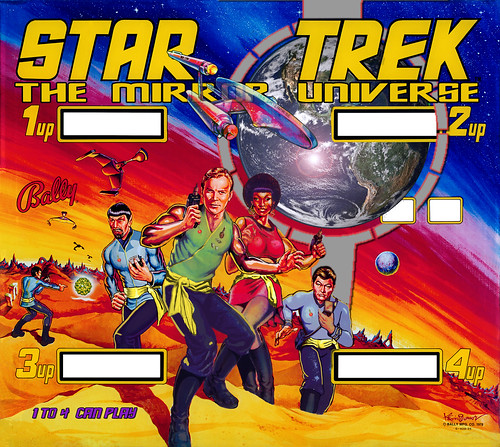
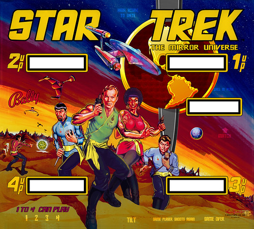
First; here an example of the original Production BG:![]()
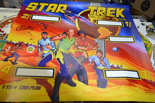
And here's My current revision of the BG I've modified:![]()
I'm not sure about the nasa render of earth replacing the planetoid... I like it... but it may be too much for the BG.2/21/2014: Received the Star Trek: Mirror Universe translite from GameOnGrafix.com today... Overall I think it looks pretty damn sweet.
![]() This weekend I hope to start cutting out the windows for the nixie tube displays and begin mounting it to the Acrylic I hope to get tomorrow from RegalPlastics.
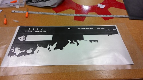
This weekend I hope to start cutting out the windows for the nixie tube displays and begin mounting it to the Acrylic I hope to get tomorrow from RegalPlastics.2/24/2014: Right now; the artwork is a translite - as a result; I want to make sure the lamps behind it don't wash out the colors and I need to provide a mechanism to enable the hidden text which is illuminated by said lamps. So I used a black layer to create a "lite blocker" layer which if successful will be sent to the vinyl cutter at Techshop where it can be use to create the dark silver layer necessary to "block" said lamp light.
I took the ipdb.org picture, straighten and scaled it in photoshop then used it as a template to enable the custom "silver layer" for the mirror universe:![]()
I wanted:
1) the yellow part of the sky to "glow" and contrast the dark planet side features.
2) the pants of the crew to be dark (unlike the original).
3) Artists signatures to glow.
4) Hidden text is an Original Series font.
5) Gold parts of logo glow... as does some shading on the red part of earth.
6) Primitive ruins glow.
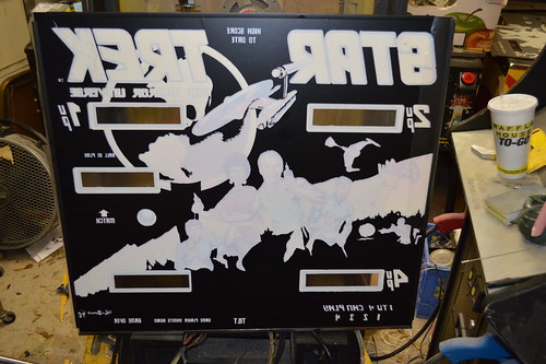
Here's a rendering of what it should look like if the lite block comes out like I hope:![]() The hardest part is going to be getting the dark to register closely to the translite.
The hardest part is going to be getting the dark to register closely to the translite.
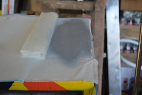
3/6/2014: Just after work Tonight - ClayD (clay), Bess, and I worked on vinyl cutting the light blocker from Black vinyl on Techshop's Cutter. Here's the bottom of the LiteBlocker, Weeded on transfer tape; ready to move to the backside of the glass:![]()
And after some work getting it aligned right:![]()
Then We cut the top lite blocker and after about 1.5hrs working on the top; This is what I can show you:![]()
Here's a picture with it backlit by the overhead fluorescent lights in my garage. Best I can do right now as I'm waiting on USPS to deliver my CometPinball LED order.![]() Some slight registration issues in a couple of spots; Due to workflow issues between photoshop (raster -> path) ... then to CorelDraw. I think at some point one of the conversions grew the mask by a 1/4" causing registration issues in some areas. If I have time I'll try to trim it up a bit more with an xacto knife before TPF.
Some slight registration issues in a couple of spots; Due to workflow issues between photoshop (raster -> path) ... then to CorelDraw. I think at some point one of the conversions grew the mask by a 1/4" causing registration issues in some areas. If I have time I'll try to trim it up a bit more with an xacto knife before TPF.
Anyway; overall really happy with the results. -
CNCed Assemblies
04/07/2014 at 07:39 • 0 comments10/21/2013: Between stenciling sessions the house got struck by lightning about a week ago... so I've been digging out of the random bad electronics and such. One of which is my Color LaserJet which I need to finish the apron.
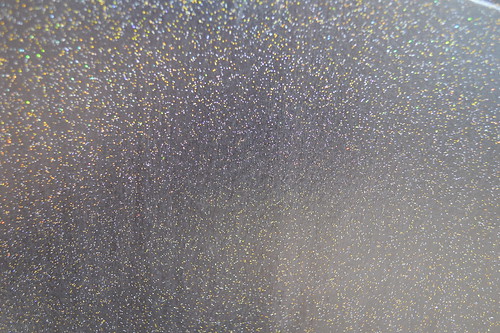
Anyway; tonight after dinner I did a marathon session at Techshop... leaving just after 10pm. The main thing I did was put the "base" on for the Apron. Like the cabinet; I wanted it black with a holographic star field. So I did a base coat in black and followed it up with some clear powdercoat with the holographic flakes in it. Here's a closeup shot of the powdercoat:![]()
I'm planning on waterjetting the inlayed pieces out of some 22ga steel and then doing a heat transfer of the graphics onto those pieces. Here's a mockup of the overall look; if it works as I hope it will.![]() 11/19/2013: Early last week I had a few minutes after work; so I went to Techshop and waterjetted some apron pieces out of some mild steel sourced from lowes. After cutting; I sandblasted them and This weekend I put them under some 220grit sandpaper to remove the coarseness added by the sandblasting. Once I had a smooth surface; I powdercoated them with some "Mirror chrome".
11/19/2013: Early last week I had a few minutes after work; so I went to Techshop and waterjetted some apron pieces out of some mild steel sourced from lowes. After cutting; I sandblasted them and This weekend I put them under some 220grit sandpaper to remove the coarseness added by the sandblasting. Once I had a smooth surface; I powdercoated them with some "Mirror chrome".
A few months ago I sourced some "SinglePrint (tm) Multi Surface Laser "no weed" " paper from them during a sale. The idea here is that using a heat press; I'd be able to "bond" laser printed graphics to the powder coated surface. Then be able to apply the needed clear powder coat over the label to give it a single resilient surface.
With the label printed using my color laser jet; I proceeded to bond the label to the substrate. I didn't have a heat press and I really didn't have the room for one anyway... so I thought I'd use a household iron. Once I received the paper; the included instructions said in italics "do not use a home iron". Then I remembered I had a hot laminator which I used in attempting to make homebrew PCBs using laser paper. The laminator claimed it did 300F max... and would apply some pressure; so I figured what the hell. worth a shot.
I preheated the substrate in the toaster oven to 300F and then applied the mirrored SinglePrint to the it and ran it thru the laminator about a dozen times. When removing the paper; it hadn't bonded to the surface. Humm. However, it was in place so I ran it thru twice to re-flatten the paper to the substrate... at this point I had nothing to really lose; so I put the substrate+paper back in the toaster oven set to ~325F. I let it bake there for about 2minutes; then quickly transferred it to the at temp Laminator. Running it thru 3 times. The returned the combo back to the oven for another heat session. I did this for about 4 times then let it cool for about 30seconds before peeling the paper from the substrate.
This time it was better; but not perfect.![]() :( As you can see; some of the label stayed with the paper.
:( As you can see; some of the label stayed with the paper.
I could "erase the label" and try again; but the label isn't really "solid enough" for my tastes. The toner is somewhat transparent which leads to muddled colors against the metallic background. It's probably be perfect on a white powercoated substrate.
I may try to source some vinyl labels in order to get the look I think I want.
Here's the other apron pieces positioned on the apron:![]()
![]()
12/09/2013: I received the vinyl decals from Callie Graphics. I went ahead and installed them on the powder coated blanks:![]()
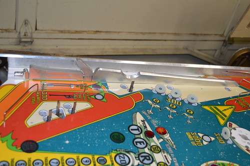
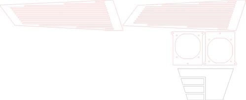
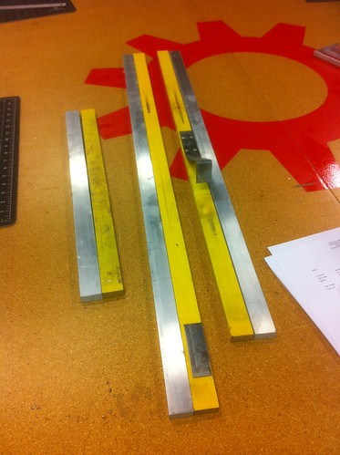
12/28/2013: While I waited for some clear; warmer days for the clearcoat... A friend (Ken) and I went to Techshop to work on the PF rails. I didn't want to put yellow painted wood back on the PF... I wanted something which would tie the machine together. I measured the wood and created a CAD file with the exact measurements. The plan was to cut these parts out of 1/2inch 6061 aluminum. I sourced the Aluminum from a local supplier in 4ftx4inx0.5in dimensions. This DXF file was then sent to the waterjet machine at techshop which results in the following parts:
![]() If you want to watch the Waterjet in action cutting this piece; see Youtube:
If you want to watch the Waterjet in action cutting this piece; see Youtube:
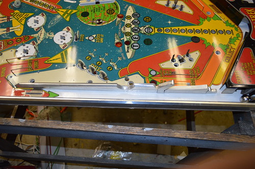
I wanted the tops of the rails to look like knife edges; but no so much that they would be a danger to anyone working on the machine (Read: Me). Ken (fc2sw) helped me put the 45 degree angles on the aluminum using the Jet#1 manual milling machine. Once the rails were milled; I proceeded to drill and tap the appropriate holes in the bottom side of the rails. For the purposes of this test fit; I used #6-32 x 5/8" machine screws. The result:![]()
While I had the rails attached; time to test fit the apron and shooter gauge:![]()
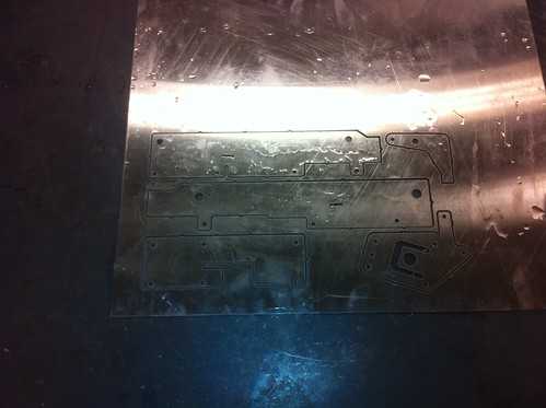
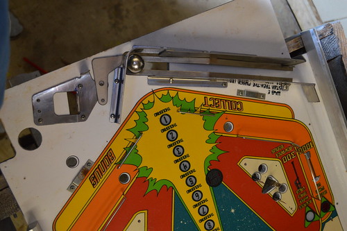
1/20/2014: it was time to begin looking at the "inlane" mechanics - namely the ball eject mechanism and the shooter lane. Initially; I had hoped that I could just "flip" the inlane and ball trough parts with the left shooter. Turns out that it wasn't really possible. As a result; I'm currently importing the parts into CAD so they can be mirrored. The Plan is to cut the parts out on Techshop's WaterJet when it comes back online. Today was that day. I had to cut new eject brackets as well as the ball trough as mirrored images. I decided I wanted to cut all the pieces out of 16gauge stainless steel so I would never have to worry about rust on these parts. :D
Here's the "flattened" brackets coming off the waterjet machine. Took about 20minutes of machine time to cut these badboys:![]()
Then I spent some time on Techshop's JET finger break bending the brackets into their correct orientation. Here's the final product vs the original brackets:![]()
Once I got home; I assembled the ball trough giving us this:![]()
I still have to assembled the eject solenoid and the eject bracket; need to order some parts from McMaster-carr to finish the eject assembly.1/20/2014: If you recall; there was a interactive portion where I asked people to speculate on what this was...
![]() ...its now time to answer that question.
...its now time to answer that question.
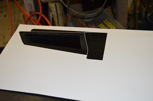
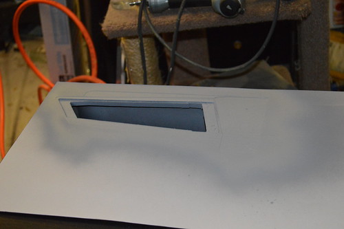
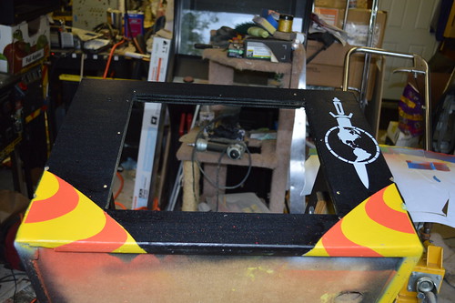
With the Eject lane in position; I was now able to install the shooter lane. This item above was carved out of 18x4inches of 1/2inch thick aluminum. When assembled it becomes the inside "guide" of the ball lane. Nobody guessed it's function; but that's ok. Now you get to see it in all it's splendor.
The pieces make up my rendition of the "Terran Sword of Conquest" as correctly identified by SaminVA here and on Pinside. I carefully cut out the 3D pieces and assembled them into the sword. The sword is made up of the little nobby thing you club someone on the head with... the handle... the hilt... and the blade itself. Each one of these pieces are bolted together with two pieces of steel. One JBwelded in the knobby thing with a set screw at the base of the handle.
The second steel rod is jb-welded to the sword blade. A set screw fastens the hilt to the rod, and the rod to the handle. No; it probably wouldn't make a good sword this way; but it's really just an ordimental piece. With the sword assembled; it's time to bolt it in it's place on the PF:![]() Now I think you guys can see why I went with a "bladed" side rail... the two complement each other quite well.
Now I think you guys can see why I went with a "bladed" side rail... the two complement each other quite well.
Another angle with another surprise feature of the PF...![]()
Several months ago; I contacted Cliffy at PassionForPinball.com and asked him to do a custom inlane switch protector for this project. He graciously agreed. For inlane switch; he cut me a custom Enterprise switch protector which I cnced a place for it making it "level" with the PF wood/clear.
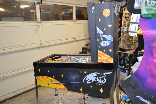
Here's the mandatory money shot for the kids at home:![]()
Starting to look like a Pinball machine now; isn't it?A couple of weeks ago; I did a pretty big PinballLife.com order... part of which was those awesome new Aluminum Flipper bats:
![]() Today; I executed the strategy for these bats. First went ahead and powdercoated them black... then a second clearcoat powder with the metal flake seen on the apron. Once I had the bat powdercoated; I laser etched a jig on the tormac laser cutter at techshop. This etch allowed me to position the bats in such a way that they ready to get their treatment:
Today; I executed the strategy for these bats. First went ahead and powdercoated them black... then a second clearcoat powder with the metal flake seen on the apron. Once I had the bat powdercoated; I laser etched a jig on the tormac laser cutter at techshop. This etch allowed me to position the bats in such a way that they ready to get their treatment:![]() The Bats go into the Laser cutter to get their dagger etches:
The Bats go into the Laser cutter to get their dagger etches:![]() .
.
I hear the audience screaming for a money shot... who am I to argue?![]() .
.
1/27/2014: I needed to work on the eject mechanism. I carefully measured the standoffs on the original part and engineered an alternate plan since I didn't have the time to replicate the part exactly. Instead I opted to buy some off the shelf threaded inserts with nylon sleeves.
For the base which holds the eject bracket; I got a 7/8" threaded #8-32 standoff from Master-Carr.com #91125A210. This piece would be mounted to the top with an #8-32 screw and would provide the rotation point for the eject bracket. To space the arm off the base I went with a 3/8" nylon spacer with 1/4" I.D. and 1/2" O.D #94639A141.
Then goes the bracket arm. For the top of the bracket; I went with a PRess-Fit Drill bushing, 0.25" ID, 0.5" OD @ 3/8" length or #9491A252. I topped it off with two flat washers (think they were 1/4") and star washer and another #8-32 machine screw.
For the plunger arm which goes into the solenoid; I went with a 0.25" tall round spacer with a 1/4" OD and and 8-32 screw thread, #91125A140. The nylon spacer on top was a 1/8" long with 0.25" ID and 0.5" OD.
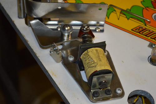
Here's a picture of the original eject mechanism vs the new one:![]()
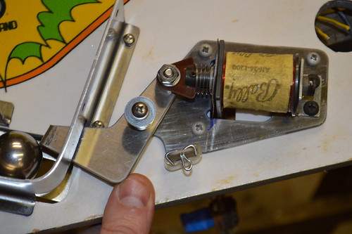
Here's the mechanism with the coil and other hardware transferred:![]()
And mounted in the PF:![]()
My only concern is vibration loosening the #8-32 screws holding the threaded inserts in place. As a result; I may end up locktite-ing the screws in place later. -
Under Playfield Assembly: Custom PCBs
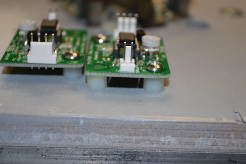
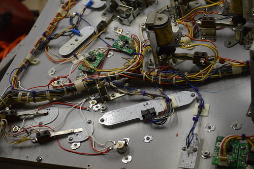
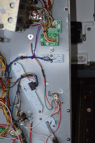
04/07/2014 at 07:26 • 0 commentsI marked the mount holes with a center punch; and proceeded to drill and tap each mount hole for a #6-32 nylon standoff as the light boards were mounted. Here's the PF with the proximity sensors mounted:
![]() And a close up showing a set of PCBs mounted with the coil leads going into the slots:
And a close up showing a set of PCBs mounted with the coil leads going into the slots:![]() With the PCBs mounted; I could then transfer the wiring harness from the donor PF to the Mirror Universe. Ofcourse it too had to be mirrored but that was easily accomplished by flipping the harness:
With the PCBs mounted; I could then transfer the wiring harness from the donor PF to the Mirror Universe. Ofcourse it too had to be mirrored but that was easily accomplished by flipping the harness:![]()
Now the fun of crimping connectors and re-soldering coil/switch terminals begins.
I also need to re-assembly the GI circuits/lamps. The cheapskate in me wants to try an re-use the old GI lamp sockets. However, the do-it-right guy in me; want to order new GI lamps so I won't have to deal with the damn flickering due to warn-out GI lamp sockets. Yes; I know you can solder/hack an old GI Lamp to work... but my experiences has been it doesn't work on every lamp.2/10/2014: It's was an awesomely mild weekend here in Austin; so I spent quite a bit of time in the garage working on the underside of the Playfield.
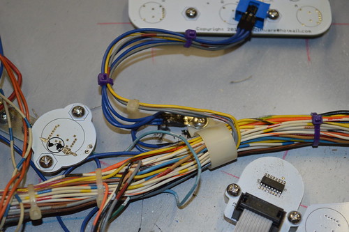
Thru the cold snap earlier in the week; I sent an internal goal of wiring the GI circuits/Lamps with color coded wire - A color a night. Rather than wiring each lamp with a bare stapled wire - I point-to-pointed each in it's specific color. IE Green, orange, red, and white. With the GI squared away during the week; I spend this weekend tackling the Hot common of the switch illumination (Blue). I also crimped my fingers swore; as I completed the Inserts wiring.
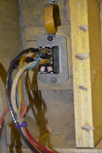
For the top GI connection; the original harness had two blue wires which were soldered to the "Common" of the lamp matrix. Instead I made a custom harness out of some 22gauge blue wire. Each one of these lamp boards had to be wired into that common.![]()
I tinned a piece of raw copper clad (blank circuit board material) and used it as a common tie point for the upper playfield's common hot. Each board was crimped to a length of blue wire and it was soldered to this tie point. The inserts were then crimped and installed on the connectors. Each LED board has a header so it can be uninstalled and fixed if necessary. For the upper playfield; A chain of 22awg blue wire moves between each led board in a circle; so in effect - each board has two 22AWG paths to hot. This should help with redundancy and supply more than enough current flow to lite the leds on the board. In the case of the upper two boards; they have 4pin connectors ... with 2 Anodes and the 2 signal wires.
For the middle of the PF; I tapped into the blue wire harness and used a rounded barrel terminal to house the common hot. This common point feed the Klingon LED board as well as the center Enterprise inserts.![]() 2 qty 22AWG blue wires feed the center inserts common point:
2 qty 22AWG blue wires feed the center inserts common point:![]()
I had to cut the tie wraps for the middle of the harness and feed some of the shorter wires between the drop target inserts and the led nacelle boards. With this new route; I had enough slack to make it to the large center insert connector for all signals.
Finally; I added another common hot tie point for the center Xk's inserts:![]()
I'm not real happy with the way this turned out... the wiring harness and connector are in the way of each other. Can't really be helped at this point; but you can still disconnect the board with minimal effort so it's still a win.
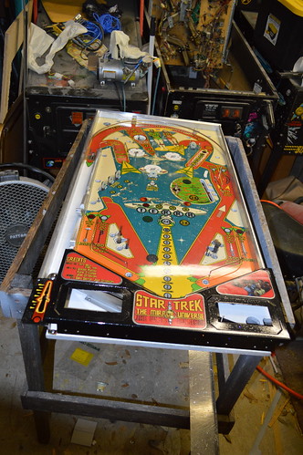
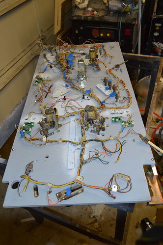
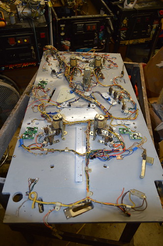
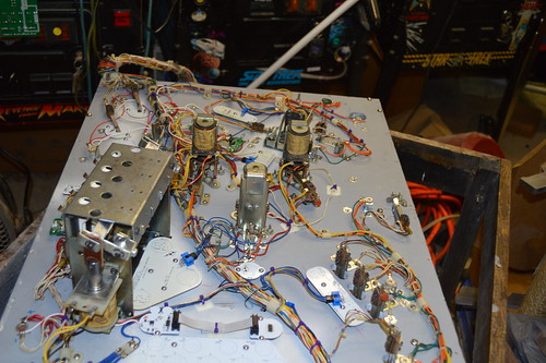
At this point; I'm about 80ish-% complete on the bottom side of the PF:![]()
What's left to do on the bottom side?
1) Still need to wire in proximity sensors.
2) Flippers
3) Slingshot switches
4) Drop target assembly
5) Wire GI to nacelle boards; need to double confirm PSU board outputs the polarity I think it does for the GI so I don't hook it backwards.
6) Mount outhole switch and inlane switches.
2/19/2014: Tonight I put the near finishing touches on the underside of the Playfield. I ran out of Butane for my cordless soldering iron; so I couldn't solder in the new fuse block for the solenoids. I tried in vane this weekend to source some butane from both Lowes (was out) and Walmart (doesn't carry?!)... so; meh.
Anyway; the red star posts from the donor playfield are already in the ultrasonic cleaner... so hopefully; I can start assembling the top of the PF tomorrow night.
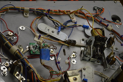
Here's detail pictures of the 99.9% PF all wired up:![]()
![]()
![]()
![]()
-
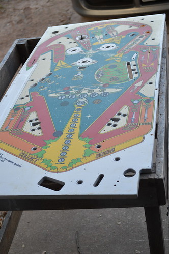
Table Art becomes Reality
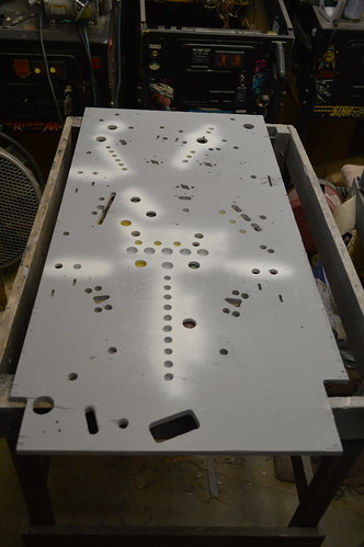
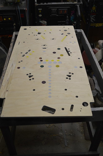
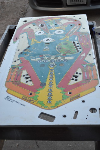
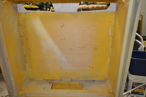
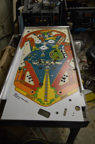
04/07/2014 at 07:16 • 0 comments12/09/2013: With the Laser Cut Inserts finshed it was time to work over thanksgiving weekend; I worked extensively on the PF. I started by spraying backside of the PF with grey primer ... unsure why the older Bally PF had the grey paint on the backside... but I figured when in Rome; do as the romans do.
Once the grey primer was dry; Sprayed the inside of the insert holes white; partly due to the Romans... partly due to the desire to have a clean looking insert. Here's the back of the PF trimmed up and sprayed.![]() With the white dry; I began gluing in the inserts. Once I had the inserts glued inplace and dry; I took a 80 grit orbital sander to the whole PF to level the inserts and remove the white primer. Here's the PF at 80 grit:
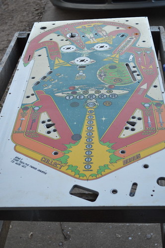
With the white dry; I began gluing in the inserts. Once I had the inserts glued inplace and dry; I took a 80 grit orbital sander to the whole PF to level the inserts and remove the white primer. Here's the PF at 80 grit:![]() And again at 220grit:
And again at 220grit:![]()
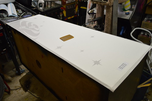
Then I proceeded to sand the inserts to 500 and 800 grit. At this point I considered the PF ready for ClearCoat. For this I used ChromaClear 2part 4:1 automotive clear. I put down one light coat and 3 medium coats. Heres the PF after clearcoat:![]()
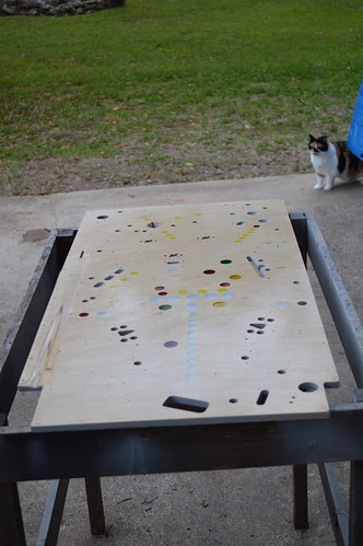
I let the clearcoat cure for a little over 24 hours; then sanded it flat with 220grit orbital sander to remove the orange peel and give the inserts another flat process. The PF/inserts needs to be flat so the sign shop can print the insert circles and artwork without any gaps in the art.
Here's the PF being back lit by shop lights:![]()
On Friday afternoon; I took the PF and artwork files to Austin Color Labs so they can put the artwork directly on the PF. I hope to hear from them by end of week with a printed PF. When the PF gets back from the printers; my plan it to put 4-6 coats of clear coat over the art then sand flat and polish to a shine.
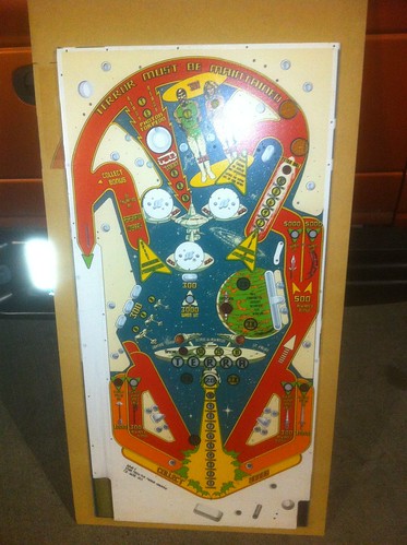
While I wait for the PF; I'll try to clear coat the decaled apron inserts... if we get a warm day in the near future. In the meantime I have PCBs to assemble; including the ATX PSU board.12/19/2013: Got the Playfield back from the great people at Austin Color Labs...
Remember; this was direct printed onto the Playfield:![]()
Honestly; The PF looks awesome except they made an error and sprayed most of the PF white before laying down the color. I supplied the "white" file... but not sure what happened. The inserts are fine; just the shooter was suppose to be bare wood. They said if I wanted; I could sand it back down and they'd redo it. I think I'll just leave it as-is; I could nickpick the bare wood issue; but Its bright and growing one me.
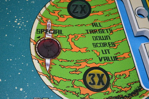
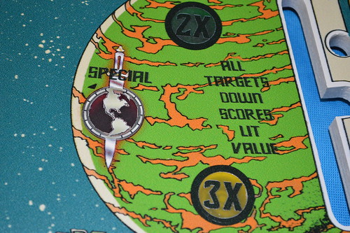
Also something's up with the red special insert (over planet)... somehow the paint didn't seem to work right over that insert. May try to use a water slide decal to "fix" it.12/28/2013: Been working on the Playfield over the holiday break. Not making as much progress as I'd like... but here's some.
First; I needed to tackle the Special insert.... basically; something went wrong at the printer and it didn't come out right:![]()
I took the graphic file back into Photoshop and trimmed a new copy up for printing on some white water slide decal paper. Some patience and water yields this corrected implementation:![]() Much better.
Much better.
Some black sharpie on the trimmed edges and a couple coats of acylic clear and that area is ready for the 2part automotive clear coat.1/5/2014: Lots happening behind the curtains... but thought I'd take a break to update the worklog.
ClearCoat is on the Playfield I put about 6 coats of clearcoat on the surface to ensure I didn't blow thru the clearcoat and destroy the art underneath. I waited about 24 hours before beginning the process of re-leveling the surface.![]() You'll note that I still had some "orange peel" problems with the clear coat.
You'll note that I still had some "orange peel" problems with the clear coat.
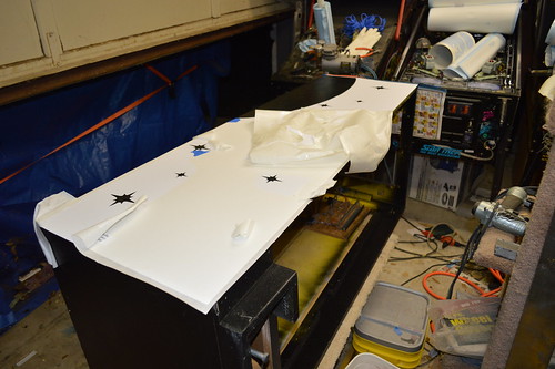
I needed to remove the orange peel so I started by sanding with 220 grit orbital sander:![]()
Then the hand sanding began with 320:![]()
wet sand 500:![]() NOTE: I wouldn't recommend wet sanding a traditional PF. I've had issues with the plywood swelling under the clearcoat. In this case; I used a spray bottle to wet the surface and then used the wet/dry sandpaper. I did this because the clearcoat under the art and the white under the art did an excellent job of sealing the wood around the cnced holes. The sprayed water just beaded on the surface.
NOTE: I wouldn't recommend wet sanding a traditional PF. I've had issues with the plywood swelling under the clearcoat. In this case; I used a spray bottle to wet the surface and then used the wet/dry sandpaper. I did this because the clearcoat under the art and the white under the art did an excellent job of sealing the wood around the cnced holes. The sprayed water just beaded on the surface.
wet sand 800:![]()
At this point; with this era of machine... I might have stopped here for a "matte" finish; but this is "The Mirror Universe"... so maybe I should put a mirror shine on it.
wet sand 1000 followed by 1500:![]()
Closer... but that still won't do.
I'd done quite a bit of sanding... all within 24hrs of laying the final coats of clear; so I decided to wait another 24hrs for the "time to decal" interval on the paint can.1/5/2014: So I waited at least a day; but in reality... I think other aspects of the project got in the way; so yesterday I got back to addressing the playfield shine - or lack there of. I chucked a buffing cloth into the cordless drill and proceeded to use rubbing compound on the clear coat:
![]() Then polishing compound:
Then polishing compound:![]() And two sessions of Carnauba Wax:
And two sessions of Carnauba Wax:![]() Yeap; I think we'll call that a near mirror shine.
Yeap; I think we'll call that a near mirror shine. -
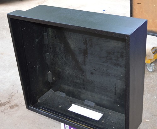
Donor Head work
04/07/2014 at 06:50 • 0 commentsAfter visiting with Modders-inc.com at Quakecon 2013, I picked up a donor head from DonW in Garland, TX. Don graciously donated this head to the Mirror Universe project.
It started life as a Supersonic head... and was a rough from a paint flaking/ding perspective. All of this mattered nothing to me... as it was going to be dye/stained black just like the cabinet. Here are some before shots of the head:![]()
The back vent hole were coming apart; good because I wanted to improve the ventilation anyway...![]()
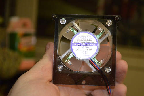
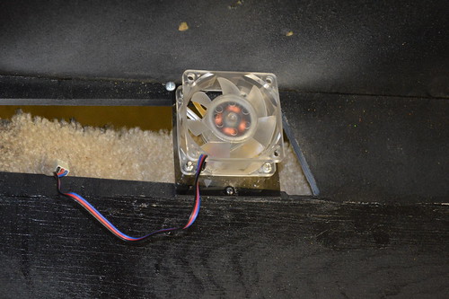
I went about destructing the head... to create new vent holes. Since eventually I plan to put more than just the original boards in the head... I decided I wanted some active cooling (IE DC FANs)... What better way to integrate vents... but using something from the Enterprise.
Using the great work by colosseumbuilders.com, I recreated the Enterprise's impulse engines in CAD. The resultant CAD file yielded the following rendering of the DXF file. In order to practice for the upcoming Playfield CNC work; I wanted to practice with by CNCing out these vent holes in the Russian Plywood. Ken and I went to Techshop.ws this past Saturday and CNCed the back vents:![]() Once I got home; Saturday night I began re-assembling the head:
Once I got home; Saturday night I began re-assembling the head:![]()
![]()
![]()
Then I lightly sanded and vacuumed the inside of the head to prep it for interior paint:![]()
This time I decided to paint the inside prior to staining the outside; so:
![]()
After the interior dried; I needed to replace the Veneer which I removed during the deconstruction phase.
![]() I thought about going to woodcraft to get it; but really; I didn't want to drive 30minutes in traffic... so I opted to get the iron-on type from Lowes. It comes in a roll; and you melt the glue with an iron.
I thought about going to woodcraft to get it; but really; I didn't want to drive 30minutes in traffic... so I opted to get the iron-on type from Lowes. It comes in a roll; and you melt the glue with an iron. ![]() The smaller roll of veneer was on clearance; so I opted for it... but turned out to be a hair short. I filled the seams with Plastic Wood filler so the seams wouldn't be visible on the back without a close inspection.
The smaller roll of veneer was on clearance; so I opted for it... but turned out to be a hair short. I filled the seams with Plastic Wood filler so the seams wouldn't be visible on the back without a close inspection. ![]()
Not sure what I'm going to do about the small section... worst case I'll apply a patch after-the-fact.
After some lite sanding with the orbital sander the back and the head was ready for the Black Dye:![]()
followed by the Black Stain:![]()
Even the bottom didn't escape the black of space...![]()
The plan is to let the Stain/Dye cure overnight. Then I'll begin to spray the Polycrlic Satin clear coat over the stain to seal the wood and prep is for future Stenciling.![]()
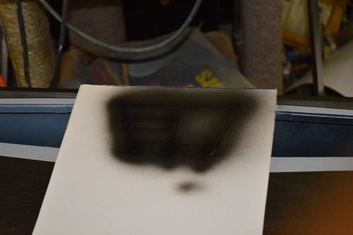
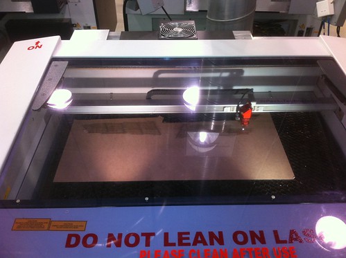
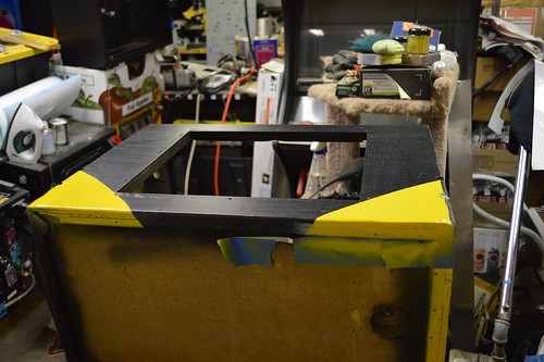
8/20/2013: This past weekend; I intended to wrap up the Impulse Engine modification to the Mirror Universe pinball head. Unfortunately it spilled over to Monday; mainly because I couldn't get my Laser cutter into a completely operational state.
Anywho; The intent was to make the vent holes to look like the Enterprise's Impulse Engine. To do this I created a stencil using the same scale and rendering as before. Since My laser cutter only has a 12x24 table; I had to only do 1/2 the stencil opting to flip it for the opposite side. Here's the stencil I created:![]()
I laser cut this out of dry erase poster board and sprayed it lightly with some stencil spray adhesive. Here it is positioned for the left Impulse Engine vent:![]()
Since I didn't have any grey spray paint on hand... and it was near or after midnight; I opted to spray with primer grey:![]() I then flipped the stencil (after the primer had dried for a couple of hours) and sprayed the other side with light stencil adhesive and then grey primer:
I then flipped the stencil (after the primer had dried for a couple of hours) and sprayed the other side with light stencil adhesive and then grey primer:![]() Now I needed to do some shading of the upper piece; So I used the drop pieces cut from the stencil as a stencil. Adhesive and some transparent black airbrush paint:
Now I needed to do some shading of the upper piece; So I used the drop pieces cut from the stencil as a stencil. Adhesive and some transparent black airbrush paint:![]() Next I needed to stencil the center panel lines. I had already laser etched the panel lines into the wood; but I decided attempting to hand paint the etch lines would be problematic. Cue Stencil number 2:
Next I needed to stencil the center panel lines. I had already laser etched the panel lines into the wood; but I decided attempting to hand paint the etch lines would be problematic. Cue Stencil number 2:![]() Adhesive, positioned:
Adhesive, positioned: ![]()
Sprayed with Black Opaque Airbrush paint:![]()
With the Stenciling complete; my attention returned to the Vents themselves. When I CNCed the wood; I also Laser cut a grill based upon the original render of the engines. The CorelDraw file looked like so:![]()
As you can see; there are two grills (finger guards if you like) and two 60mm Fan brackets. The grills were a particular bitch to cut... The heat would cause the grills to warp. I went ahead and cut them; only to find that one of the long lines broke on one of the grills. The result of these grills it pictured here:![]() Upon reflection; I determined that the cause of the warpage was proably the amount of heat "transferred" during the long cut lines. The "spaces" between the grill lines were about 0.1"... while the solid part of the grill was ~0.8". This ratio was critical to the look I wanted (and to match reference photo). I also knew that the long runs were just too flimsy; so I had to modify the grill design to keep more "solid" acrylic in place. This would strengthen the grill and should help reduce the heat-induced warping. Design Rev#3:
Upon reflection; I determined that the cause of the warpage was proably the amount of heat "transferred" during the long cut lines. The "spaces" between the grill lines were about 0.1"... while the solid part of the grill was ~0.8". This ratio was critical to the look I wanted (and to match reference photo). I also knew that the long runs were just too flimsy; so I had to modify the grill design to keep more "solid" acrylic in place. This would strengthen the grill and should help reduce the heat-induced warping. Design Rev#3:![]()
I also changed the order of cut on the file. I opted to do the periphery outline AFTER the center grill portions were cut. Again in an effort to minimize heat transfer and aid in preventing cutting mishaps if I had to restart the cut.
Here's the Laser At Techshop.ws cutting the Rev3 grills:![]()
With the new grills complete; it's time to begin the assembly of the fan brackets:![]()
Installed:![]()
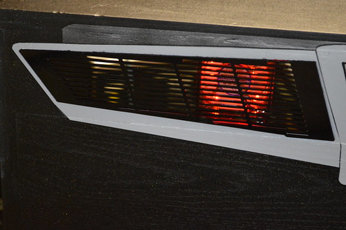
And the Test fit along with overall shot:![]() And a Closeup of the grills:
And a Closeup of the grills:![]() With that the back of the Star Trek: Mirror Universe head is complete. The grills were wrapped up and stored safely until the final stenciling is done on the sides and the whole piece is clear coated.
With that the back of the Star Trek: Mirror Universe head is complete. The grills were wrapped up and stored safely until the final stenciling is done on the sides and the whole piece is clear coated. 9/19/2013: A couple of days ago; my custom stencils came in from TwistedPins. I started with the head because it was still on the hydraulic table from the fan installation. I decided I wanted to use the same head stencils as the original bally; just change up the colors a bit.
I started by laying down the yellow stencil:![]()
![]()
At this point; an improvement I'd suggest to these stencils is that for the first layer... the "red" covers should be removed. IE the planetoids shouldn't have any masks "inside" the oval shapes. That way you lay down a solid color and the second color (red) goes over the yellow so there are no registration offsets. This is what I did; I went ahead and removed all the squiggly shapes from the planetoids.
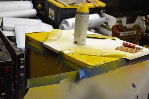
With the stencil ready; I taped off the surround areas with newspaper and put down some grey primer. This was done mainly to get the "grey" which I had chosen for the enterprise. Yellow generally goes over light grey than black so I sprayed everything.![]()
I waited overnight for the grey primer to cure then masked off the enterprise grey and sprayed down some "Gold yellow" spray paint. I decided to use spray paint as it is easier to clean up than trying to spray the sign lettering enamel I used for the Bally Star Trek repair many years ago.![]()
I let the yellow dry about an hour before carefully removing the masking. Here's how the first stencil turned out:![]() Another night time cure to let the paint harden before I put down the red-orange stencil. I decided I wanted the planetoid to be the same colors as original. The difference was in the Enterprise as you'll see in a moment. I sprayed the planets and then the Enterprise-shadows as "Driver blue".
Another night time cure to let the paint harden before I put down the red-orange stencil. I decided I wanted the planetoid to be the same colors as original. The difference was in the Enterprise as you'll see in a moment. I sprayed the planets and then the Enterprise-shadows as "Driver blue". ![]()
I let the orange/blue combo cure in the TX sun for a few hours; then removed the masking. The Result:![]() There were some slight registration issues with the blue and grey; but really not that bad. Again; If it were me; I'd have created the stencils with the entire Enterprise in "yellow" and then have the "red" overlay cover the yellow to avoid the registration issues. I'm guessing TwistedPin did the stencils that way so someone could just do a single color... but really; the Red fades long before the yellow; so in my mind the yellow stencil should cover all the areas Red+yellow.
There were some slight registration issues with the blue and grey; but really not that bad. Again; If it were me; I'd have created the stencils with the entire Enterprise in "yellow" and then have the "red" overlay cover the yellow to avoid the registration issues. I'm guessing TwistedPin did the stencils that way so someone could just do a single color... but really; the Red fades long before the yellow; so in my mind the yellow stencil should cover all the areas Red+yellow.
Anyway; I'm digging the custom Enterprise colors. -
Donor Cabinet work
04/02/2014 at 03:36 • 0 comments7/29/2013:
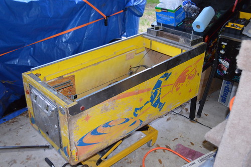
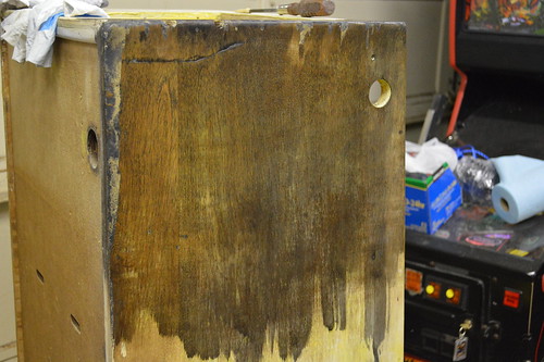
As I stated; been working on the cabinet for the Mirror universe project. I bought a couple of "project" Bally Star Treks from a fellow pinball collector out of Shertz a few years ago. These have been setting in storage for a while... and were very rough.
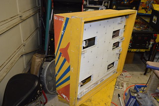
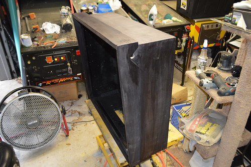
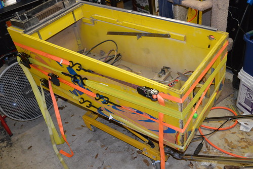
I took the cabinet with the most flaking and damage as the donor cabinet for this project. Here it is in all it glory:![]()
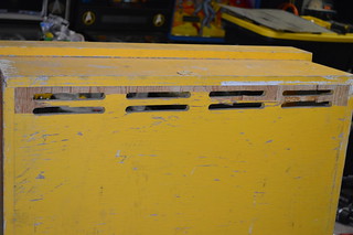
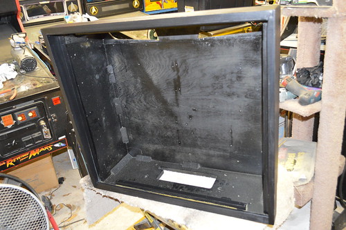
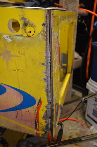
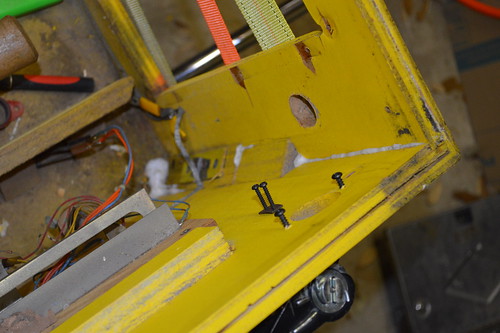
I began by stripping all the hardware (coindoor) and side rails off of the machine so I could access the state of the "bones" (ie wood) of the cabinet. I noticed that the front corners were beginning to separate.... also some of the plywood cores were starting to come apart.![]()
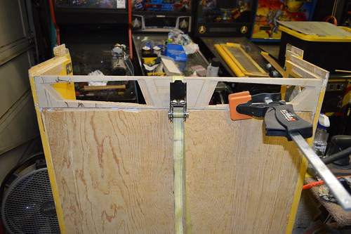
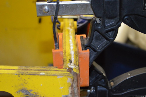
First I used some white gorilla glue to repair the plywood core:![]()
Then I used ratchet straps to re-glue both sides:![]()
![]()
I CNCed a diamond shaped piece out of MDF and glue it in the old shooter hole:![]()
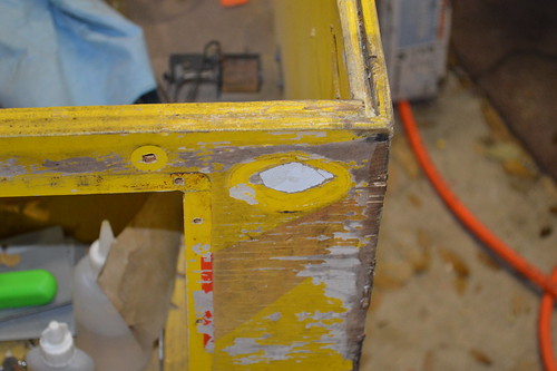
With that I began stripping the old flaking paint off with CitraStrip along the way I tried to save as much of the wood as I could. When possible; I reglued the laminate back to the plywood... or used some wood filler to fill in the rough areas.![]()
I also repaired the bottom - not pictured. 3 of the four sides had lost the plywood under the grove... which means the bottom would probably fall out at some point. I fixed this by saving as much of the plywood core on the 1 "acceptable" side... then using quarter round pieces from Lowes. The quarter round piece was secured with the same gorilla glue and some 18 gauge pin nails.
I bought some mill wax ebony oil stain as I wanted to stain the cabinet black instead of paint. I wanted something "different" looking. Here's one side stained with several coats. Looked like absolute trash...![]()
That just would not do AT ALL.
The next day I went to our local WoodCraft store ... they seemed to have a better selection of stain.
Since I was in new territory on this project; I decided to get a couple of product. The first was a Ebony Wood Dye product and the second was a Black Water-based Stain. The guy at the store claimed the dye would dye the fibers of the wood in a "molecular" like fasion ... while the Stain is pigment based (and would act more like paint). I added the later. I figured I'd buy both and try it on the cabinet.
After I got home; I stripped the back of the cabinet and put down some test swatches:![]()
Upper right hand: Ebony Dye
Upper LEft: Satin Black Stain
Lower Right: Stain over Dye
Lower left: 50/50% mix of both
I didn't like the ebony stain as is... as it still had a purple/blue hue to it.
The stain looked ok; but had a paint like view.
The Dye under Stain had what my mind thought was the best of the two. The Dye in effect raised the wood grain a little; and the stain still let the overall look like a satin look. The 50/50 worked; but wasn't as vibrant as the Stain over dye.
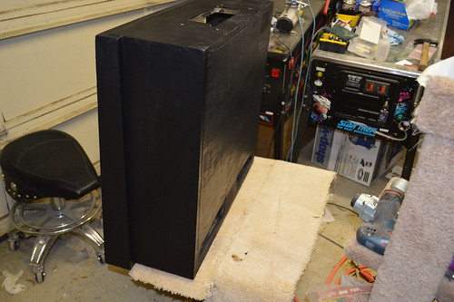
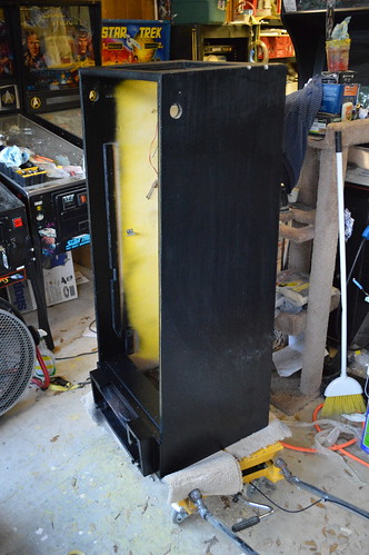
With this decision; I proceed to dye then stain the cabinet. The Outsides of the cabinet were stripped of all paint; then dyed then stained. The inside of the cabinet I decided to lightly sand the interior then spray it with a Satin Black spraypaint from Rustolem. I also sprayed the bottom side with the same Satin black so it'd look more finished.
The results:![]()
![]()
Yes... I probably could have save myself some more time by just painting the cabinet with some latex black... Or any black paint; but I kinda wanted to have the wood grains show thru the background. I may regret this decision later... but I'm currently very happy with the way it turned out.
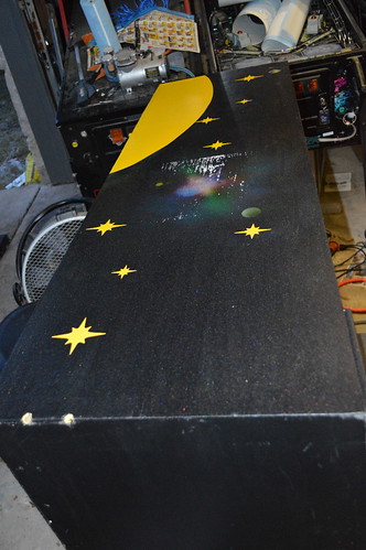
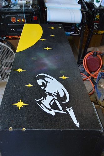
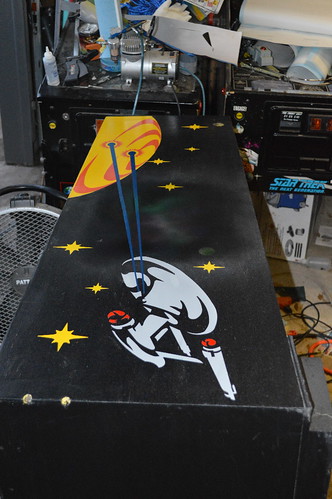
Tonight I worked on the stencil design for the cabinet. Obviously; it's going to be a black background; however, I wanted to pay a nod to the original cabinet design. I traced the existing design and pulled it into Corel Draw. Given Black background; I still wanted to keep some of the same colors in the stencil. So the stars became Yellow. The planet Yellow/Red... and The Phasers became blue. I going to make the Enterprise BattleShip grey.
I removed the Klingons ... instead having the Enterprise fire on the planet.![]()
Still need to work on the front design... and the Head. I'm thinking about keeping the Head design the same... but change the blue background to black.
Thoughts?7/31/2013: Did some more work to the side art; terminating the phaser beams on the planet. Not ideal; but probably the best I can do with a stencil application.
![]() I also worked on the front art; "inverting" the shooter location and making the color scheme similar to the sideart.
I also worked on the front art; "inverting" the shooter location and making the color scheme similar to the sideart.![]()
Not sure about the text at the bottom. Again limited by a stencil; but need to look at this further.
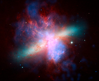
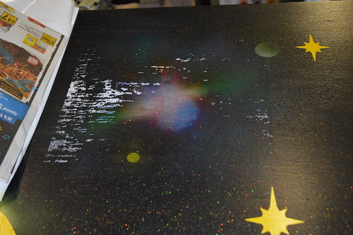
8/16/2013: I decided I wanted to do a little something extra for the background of the cabinet - approx where the Klingon ship would have been. I debated internally in my head of I wanted to go this far... in the end deciding "it's my machine; make it yours!".
I did some looking around on google images for Hubble space telescope pictures when I came across this picture of the M82 Galaxy:![]()
Remember to Click the image to get higher rez shots you can zoom in on
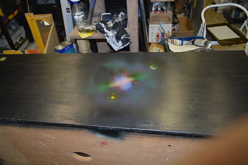
Now that I had the picture... it was time to figure out how to get in on the cabinet. I had some White backed Water slide decal paper for my color laserjet; so I figured I'd give it a shot. Some water slide work... some Airbrush work... and we are left with two similar yet uniquely different reditions of the M82 galaxy on either side of the cabinet:![]()
![]()
I coated the airbrush/decal work with some Matte clear spray paint.
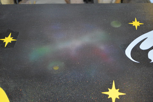
I knew I wanted to do something different with the background black... that was adding holographic gold and silver flake to the topcoat before I stencil. So I did some google searching and ended up purchasing some gold and silver flake from PaintWithPearl.com. The idea was I wanted to have a star field over the black. Nothing really special about this webstore; other than they seem to be the most competitive w/ regards to color selection as well as price/ounce.
I mixed about 1/8 a tsp of silver and 1/8 tsp of gold into the polyacrylic clearcoat I was going to spray over the black stain to seal it. With my Harbor Freight spray gun I sprayed the cabinet and head.![]()
In retrospect; the metal flake at 0.004 inch was just too small... looks more like star dust; not a starry night. Ideally; I'd have gotten several sizes and mixed them for a more random look. Here's a close up showing the gold/silver flakes:
![]()
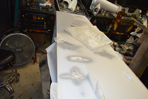
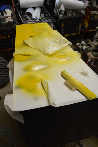
9/26/2013: Now my attention turns to the stenciling of the side cabinet. First color... yellow:
![]()
![]()
![]()
![]()
Once the yellow dried overnight; I pulled the stencil up:![]()
Yeap; that's right... The use of the waterslide decal came back and bit me in the butt. The stencil pulled the toner right off label.![]()
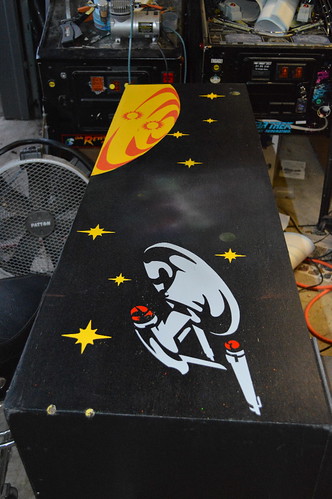
< sigh>9/26/2013: After many choice explicatives; I decided there wasn't much I could do now... so I went ahead and continued stenciling the grey; opting to see what (if anything) the Enterprise would cover. Ofcourse; I designed the decal location to be where the Klingons were; so I knew it wouldn't cover jack... but it made me feel better. I also figured if the next stencil pulled up more; I could fix it once and be done.
Down goes the Enterprise stencil..![]() This time I left the protective backing on the section which went over the waterslide decal.
This time I left the protective backing on the section which went over the waterslide decal.
I sprayed the grey primer and let it dry overnight. The backing protect the label; so I proceeded to cover the paper areas with the black stain to match the color of the cabinet. I then re-airbrushed to blend the new black with the background image. I then re-sprayed the holographic flake and clear coat as best I could with airbrush.![]()
![]()
Good as new? no. but, not too bad I guess.
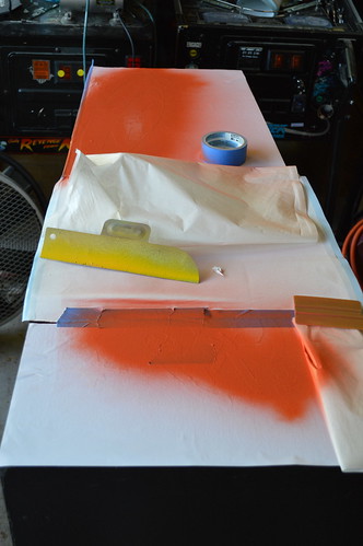
Now for the orange stencil.![]()
The orange wasn't Red enough for my Nacelles... so I sprayed them with cherry red.![]() And finally; the blue phasers:
And finally; the blue phasers:![]()
Ofcourse; the blue phasers crossed over the nebula - I had to use some of the stencil to prevent paint bleed. At this point more toner came off; so I had to do some more repair. The result:![]() I'm not real happy with the blue phasers; they tend to not show up ell on the black without a grey border. Not sure what if anything I'm going to do.
I'm not real happy with the blue phasers; they tend to not show up ell on the black without a grey border. Not sure what if anything I'm going to do.9/29/2013: Now my attention turns to the front stenciling... First the Yellow:
![]()
I decided that I'm going to start "wrapping" the images under the cabinet to give it a unique look.![]() Orange:
Orange:![]()
![]() Grey:
Grey:![]() And the final result:
And the final result:![]()
With that; I've completed one of each side of the cabinet. Now the "Busy" work of finishing the other sides of the cabinet begins. -
Playfield Plastics
04/02/2014 at 03:19 • 0 commentsI've been working on the Plastics for the machine...
remember to click the images to get larger/higher rez renderings
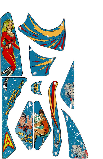
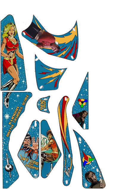
Here's what they basically looked like on a prototype machine ... I re-did the text here:![]()
Why ProtoType? Well... Yellow/Silver uniforms do not fit the theme of the known Mirror Universe... That and I really enjoy the Busty Blonde.
So; now I needed to "mirror universe" it up.
However, I'm kinda torn between two designs. First; here's a screen cap of Scotty put on one of the pieces:![]()
Changes:
1) Busty Blonde has been Mirrorized.
2) Spock has a beard.
3) Uhura has been Mirrorized - complete with black stockings.
4) Those.... um... who-knows what has been removed and cartoonized-screen-caps of Kor and the Romulan Commander have replaced them. With the req factional logos in place.
5) Scotty Screen cap from Mirror Mirror.
My issue with screencap is it kinda looks out of place with cartoonized Evil-Spock and Evil-Uhura... but "matches" the screencaps of the foes.
Option 2:![]() Took a screen cap of Scotty from The Animated Series (TAS) and heavily modified him to make it a mirrored version.
Took a screen cap of Scotty from The Animated Series (TAS) and heavily modified him to make it a mirrored version.
I'm also thinking about putting Evil-Sulu on the other arrowed plastic. But depends on which direction I go in.
Been in touch with Kevin at www.tavco.net ; unfortunately - the printer purchased by the Austin / RoundRock Techshop is only 24in wide... and the 4mil pressure sensitive adhesive film I wanted to use only comes in 36inch widths. The only material that comes in 24inch is a non-adhesive roll; meaning I'd have to find some kind of adhesive to attach the graphics to the PF.
He did put me in contact with a local printing company:
http://www.aclaustin.com/
whom may have a large format printer which can print directly to the Playfield; which should make it easier to create as I won't have to "register" and "line up" the graphics to the inserts/table.2/28/2013:
A while back; I put the breaks on further work on the Plastics. The reason I stated was that I was working on a plan to knock your socks off. Tonight is the moment I reveal the plan and work that has been done.
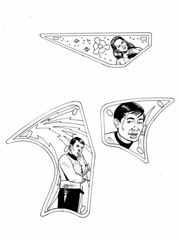
When I realized my art skils were not up to the task... I decided to consult a professional. I approched a well known Star Trek graphic novel artist with the project; and he agreed to do the work on commission. It wasn’t cheap; but I decide to do it because I was spending so much effort to make this a one-of-a-kind original; that it would just stupid (in my mind) to leave the plastics art to an armature artist like me.
The schedule we settled on was for him to deliver me Pen and Ink drawings electronically by this past weekend to enable me some time to create the plastics prior to TPF'2013. Monday he delivered the drawings.
Oh; and BTW: I'm retaining all rights to the art for now... as I have worked out final rights with the artist. No one is allowed to reproduce these for any reason.![]()
![]()
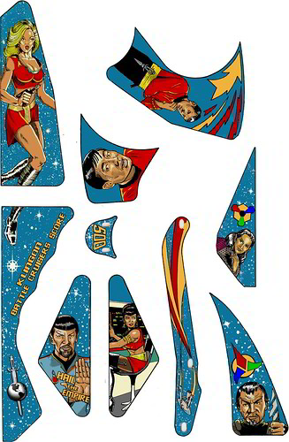
Now that I had the ink files; It was time to do some photoshop work on it ... I decided I wanted to color the drawings rather than hire another professional; thereby spending more bank.![]()
TBH; I'm very pleased with the results.
Gordon did an EXCELLENT job giving me the baseline for the art don't you think?
I may do some more work on Sulu as he looks off with the teeth.
Comments / Suggestions?
Now I need to send him the plans/Ideas for the BackGlass. First; I have to scan the existing backglass and measure the critical parameters. So; now is your chance to provide ideas for said backglass; I want to get him something by Friday.4/5/2013:
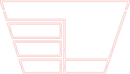
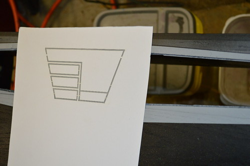
I've been working on the two of the plastics I had forgotten about.
I forgot about the orbit/arch plastics which are at the top of the PF. Might as well bang them out before I try to make the plastics. I scanned them into my computer a while ago; and took this time to clean them up and vectorize them. I tried to color match them against the new plastics shown previously - reusing colors and the like.
Additionally; I put some extras on the plastics - namely an Klingon D7 Cruiser, the ISS Enterprise, and a star field. I got the Enterprise from the promo plastic which I scanned in and cleaned up.
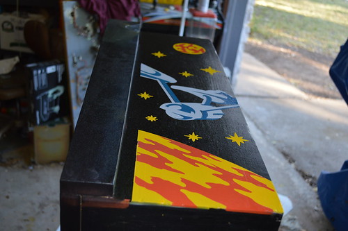
The result:![]()
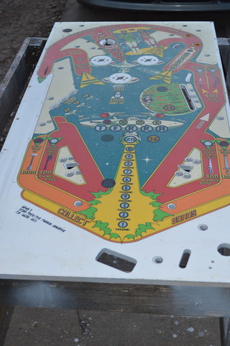
Star Trek: The Mirror Universe Pinball
A custom / unique pinball machine. This is a 1978 Bally Star Trek table “mirrored” and re-worked into a Star Trek Mirror Universe Theme.
 Steve Richie playing the machine:
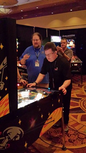


 Connecting the wires to the base of a GI lamp socket nearby.


 ...its now time to answer that question.