 zittware
-
Displays: How about Nixie Tubes?
04/02/2014 at 03:12 • 0 commentsI can’t claim originality here... as I remember the XENON machine at a past TPF which had NIXIE tubes instead of the standard VFD displays. I always thought they were cool.
Now that I’m designing Star Trek: The Mirror Universe; I’m thinking that I want to put NIXIE displays in the machine instead of stock Bally displays.
I’ve been doing some design work; and have come up with the following schematics which use the IN-12A tubes from Russia. They are nearly the same digit height as a stock display and are relatively inexpensive compared to other tubes.
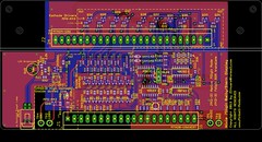
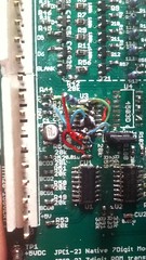
Just put the finishing touches on the silk screen for the Base board for the Nixie display.
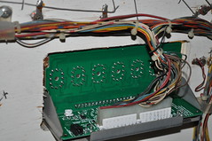
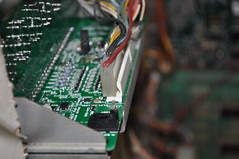
Here’s a image of the boards as they stand today.
Base Board:![]()
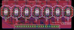
Display Board:![]()
New features added:
1) The “Right angle” Display board has surface mount LEDs under the tubes; the idea here is that when the display is “active” meaning PlayerX is up... the switched LAMP driver on the side of the display turns on these LEDs causing them to backlight the display ... to help identify which player is active. A Brightness POT on the baseboard controls the brightness.
Opto-Isolated the “lamp” input from +5V logic.
2) I added decode logic to support 7digit display ROM hacks:
Update 6 Digit Bally pinballs to 7 digit
where buy D5 =1= D6 causes the 7th digit to become active. U3 & U4 provide this functionality.
Feature is jumper selectable to for native 7digit or Rom-Hack 7digit mode via JP1.
3) Clearly labeled Test Points with voltages. Added 80V test point.
4) Additional decoupling caps near U1,U2,U3 and well as a bulk cap for 5V.
5) Nixie tube display board is at a “right angle” to the base board (like original); but is back set far enough so “front” of IN-12A displays are near same position as the VFD display.
6) HV areas “inside” dotted lines. Generous ground planes to help with thermals.
7) Same PCB sizes as original.
The Schematics are posted here for review... I’ve never designed a display before... so will probably need to do some design tweaks once I get the Tubes in.
http://www.Pinball-Mods.com/blogs/wp...ally7Nixie.pdf
At this time; the design remains my copy-protected property! Once I've proven the design; I'll consider open-sourcing the design for others to build.
I went 7digits instead of 6... so they can be used in other machines. I’ll either de-pop NIXIE_A7 or figure out how to make my Bally FW run a 7digit display.3/23/2013:
I hand assembled the base and display boards and soldered them together.
I didn't want to commit the untested display to my Bally Star Trek... so I needed to figure out how to facilitate debug.
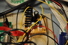
First problem was how to supply 190VDC to the HV section. Some googling found me some 555 timer circuits which would run off of a 9V.
Had most of the parts except a 250V 4.7uf cap and a pot. A trip to Frys solved that problem.
A bread board and an ATX power supply and I had a 190V psu. The ATX supply provides +5v to the display and +12V to the 190V psu's input.
Here’s a picture of the prototype 555 190V Nixie supply:![]()
Initial debug turned up a dumb assembly mistake..– I swapped U1 & U2 despite the clear labels on the silkscreen.
I hardwired the display inputs to only lite digit 1 and display an 8 (1000b). 8 because it's the digit which uses the most current given the largest area. This will allow me to verify the anode current before committing to a final anode resistor. To "latch" the 8 digit; I used my RatShack Logic pulser to toggle the LE pin.
I was able to empirically calculate the Anode resistor using the built-in test point and pot. 21.4k... now I just need to find some 22k 603 resistors to make it work. 21.4k gives me 2.5mA of anode current which is typical for the NH-12A tubes I’m using.
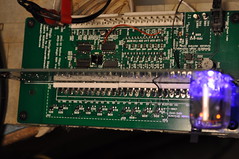
Here’s the top view of the display boards:![]()
And the money shot for the backlite display:![]()
I decided early on that I wanted the backlite to be purple rather than some other color because I thought it’d contrast nicely against the orange digits.
You can see the testpoint and Anode pot right below the Nixie tube. Obviously; these will be de-poped for “production” boards.
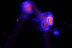
Here’s a picture I just thought was cool. A result of playing with camera shutter times:![]() With the resistor calculated; I need to focus on creating a Display tester so I can run the display thru all the digits and functions.
With the resistor calculated; I need to focus on creating a Display tester so I can run the display thru all the digits and functions.4/9/2013: More debug this wkend seems to point to the 4555 1to4 decoder circuit.
I pulled the tristate buffer (u4) and solder bridged the outputs of the 1to4 decode straight to the transistors thru a 9.1k resistor.
The display does the same thing without U4.
This points to U3 (cd4555) being the culprit.
Now; given I’ve already verified 7 digit emulation with the arduino which doesn’t work in the machine; seems to be a clue.
I’m leaning toward the output of the MPU being TTL compatible; but not CMOS compatible. I don’t think the signal to the displays is meeting CMOS high requirements for digits 5&6. According to my mpu schematics; the digit enables are driven directly by the output of a 6821 PIA.
So; next step is going to be to wire in an oscope to see what D5’s levels are.
Then figure out how to solve if hypothesis proven.
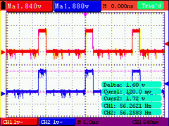
This pretty much sums it up:![]() PeakToPeak; my displays (digit enables) are only getting 1.6V for a high. Well below the cmos “good” for a 1. This is measured at R44 and R43 closest to the connector on stock displays.
PeakToPeak; my displays (digit enables) are only getting 1.6V for a high. Well below the cmos “good” for a 1. This is measured at R44 and R43 closest to the connector on stock displays.
This is the reason why my Nixie design isn’t working. I can design around this with either a transistor or some other translation logic; just not sure why the value is so low.
I see why it works on stock displays as all we need is for the high to be > ~0.7V to turn on the digit enable transistors in the original design.
Just need to confirm with other pins / people that they see similar results. I only have the one Bally Star Trek; no other era pins.
By confirming other pins; we can determine if this is a design change is warranted.4/11/2013: I did some "dead bug" rework to the existing display; basically epoxing two SMT 2N3904s to the top side of U3. I cut some traces and soldered a 20K ohm pull up between VCC and the collector of the transistors. Emitters were tied to ground. Bases were connected to the series resistors currently present in the schematic.
![]()
The goal here is to work out the kinks in the design so they can be incorporated into a FAB B board and be relatively confident the design will work out of the box.
Because the BJTs are single transistor inverters; I needed to rewire the input to U3. I wanted to reuse the existing CD4555B chip already present to keep the design similar. Turns out that by swapping A & B inputs vs the schematic; the following Boolean logic become obvious:
U3A Q1 = !B*A = D5
U3A Q2 = B*!A = D6
U3A Q0 = !B*!A = D7
Remember that when the MPU is driving A5 or A6 high; the BJTs invert that to be an active low. So the boolean math makes it logical.
The result (finally):
Click here for YouTube movie
Here are some pictures of the display installed in my Bally Star Trek machine:![]()
![]() Known issues:
Known issues:
Digits are too light when running in multiplexed mode (in a real machine); plan to drop the anode resistor to ~2.7k from 22k to brighten the digits. Not a good idea for non-pinball machines which aren't multiplexing the digit enables; but should be fine for more machines.
Need to "fix" the native 7 vs emulated 7 digit jumper selector given the need to invert D7 in native mode.5/15/2013:
I’ve completed assembly of FAB B of the NIXIE tube displays. The emulation and 7 digit native modes work as designed. I’ve posted a youtube video with it installed in the backglass.
http://www.youtube.com/watch?v=YcyABnz11KA
Obviously; the 7digit modes do not work “ideally” with a machine designed for 6digits. I may spend some time in the future to make a 6 digit “right angle” board if there is enough interest.
Need to confirm in a 7digit machine that it works properly. I already have a volunteer.
Next step is to write a blog post with schematics and pictures.
Need to send the boards out for Black PCB fabbing. -
Laser Cut Inserts
04/02/2014 at 03:00 • 0 comments1/2013: Mid week last week; I activated my Techshop.ws membership and schedule myself for the Laser cutter SBU on Saturday. No; I didn't feel like I needed the SBU; but given my issues with my personal laser cutter - I still needed to make some progress.
After class; I scheduled a 2hr block on Laser cutter#2. I wanted to use the Laser cutter to create the Inserts I'll need for the new playfield. I went to Regal plastics earlier in the week and got some material:
Translucent White @ 0.25"
Translucent Yelllow @ 0.25"
Transparent Green @ 0.25"
Transparent Yellow @ 0.25"
Transparent Orange @ 0.25"
I already had Transparent Red @ 0.25" so didn't need it.
No; I didn't need all these colors to exactly match the existing Inserts; but I wanted to experiment to find the right mix for what I wanted on my pinball table.
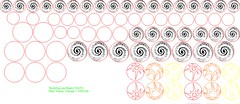
I drew up some inserts in CorelDraw X4 ... and decided that I wanted to take three different tests:
1) Try Transparent Inserts without anything. Just "clear".
2) Transparent Inserts Frosted.
3) Transparent Inserts Clear with a "spiral galaxy".
4) Transparent Inserts Frosted with a "spiral galaxy".
I figured; since I was creating my own table... might as well add some enhancements for some added details. Hence the spiral galaxy might look good.
I also figured that I don't really like "clear" inserts; some frosting would hide the bulb filament and/or the electronics/LEDs under the inserts.
Here's a Corel rendering of my work:![]()
For the frosted; I hit the acrylic with a 220 grit orbital sander... the followed up with the sandblaster. The spiral galaxy would be etched into the acrylic with the laser cutter.
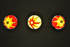
The Translucent White and Yellow look really good. Here they are compared against existing inserts and being back lit by a White #555 LED:![]()
![]()
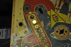
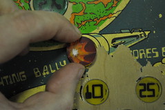
Now for the Red 0.61 insert test:![]()
Top is the clear insert, bottom is the frosted insert.![]()
Top is the clear/spiral insert, bottom is the frosted/spiral insert.
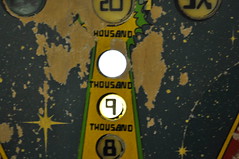
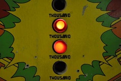
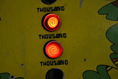
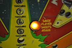
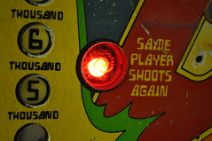
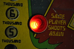
Let's try the a bigger insert... how about the shoot again insert.
Before (stock/old insert):![]()
Clear/Spiral:![]()
Frosted/Spiral:![]()
Based on the current tests; I gotta say I'm diggin the Frosted/Spiral inserts. I wouldn't do the spiral galaxy for every insert... but as an embellishment to specials like the green; red; amber inserts. I think they do a good job of defusing the led light while adding a little something extra.
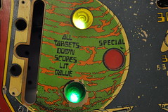
Here's the Clear Yellow and Green inserts. I didn't bother to photo each version; since I pretty much decided I like the frosted Spiral Galaxy versions.![]()
I didn't need to clear yellow; but I cut them anyway... because I need the smaller pieces you'll see next. I think I'm going to use the clear yellow inserts to represent the 3X bonuses.2/5/2013:
Observant people noticed there some details pieces on the CAD drawing I showed earlier. These detail pieces are for the Nacelle graphics in the original playfield. I was always... disappointed these warp nacelles didn't light up on the original PF. So; I wanted to see if I could change that on The Mirror Universe.
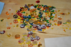
Anyone like Puzzles? If so... have I got some fun for you:
![]()
All kinds of colors of the rainbow. And no... I not real fond of puzzles.
I laser cut some plywood in about the size of the nacelle image on the PF. and put together the puzzle of Yellow, Red, Orange to replicate the nacelle. Once I had the 20some odd pieces in the correct order I "tooth pick" clamped the pieces tightly together:![]()
and then used some acrylic solvent to glue the pieces using capillary action. I made sure these pieces were tight together to ensure a tight bond was formed. I haven't really tried to "Break" these parts; but I've dropped them a couple of times and they haven't shattered.
I made two with the Yellow/Orange/Red/Yellow combo - the identical combo as the PF graphic. Since I had the pieces; I went ahead and created a combo which more closely resembles the Enterprise... W/ Red as the main color; orange/yellow/white.
Once I had the pieces welded together with the solvent; I need to make them level. However, I notices that even tho I cut these parts from the same file; their with minor gaps between some of the pieces where they didn't meet. I didn't want to see unfiltered light come from between the acrylic. I pondered; thought about Epoxy w/ some kind of dye... but remembered that I created some crafts with the wife many years ago. It was some plastics stainglass in a bottle. I had pearl white; but couldn't find the Red or Yellow. I tried Michaels... and all they had was some sh1tty martha stewart glass "paint" for $4 a bottle. "Meh" I thought. So I waited until Monday when Hobby Lobby would be open. A lunch trip turned up the exact thing I remembered:
Ruby Red Gallery Glass and the Sunny Yellow. These two oz bottles were like $2.75 a bottle. Using the bottle applicator; I filled the cracks with the appropriate color. I didn't get the Orange- because I wasn't sure Pumpkin Orange would match the acrylic orange. Since red and yellow always border orange; I could use one of the two. I used pearl white for the center "star" on the red insert.
Once I had the cracks filled; I proceeded to attempt to use the orbital sander to help level these inserts; at which one of the yellow inserts went flying into the nether regions of my garage. a quick search didn't turn it up. At that point I went to manually sanding these parts flat.
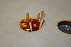
The result?![]() And the money shot:
And the money shot:![]()
I like the red a lot better than the yellow.
-
Table Art / CNC work continues...
04/01/2014 at 21:43 • 0 commentsI've been makeing some sutble changes to the PF. I changed the orbit and added some weapondry to the various lanes to fill in some "empty" space created by removing the rollover switches.
![]()
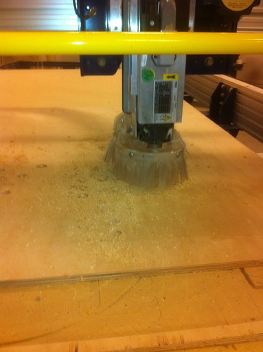
I also did the initial CAD work on getting a CNC-ready Playfield.![]()
My next step is to see if I can source some inserts from Pinball Resource. I'll need to do this before I commit to keeping the same sized inserts as on the original.finished the CNC work on the Playfield as I have a 1pm reservation on the Techshop.ws CNC machines for Saturday. Earlier this week I got some Russian Birch in 4x8 sheet to create the PF on. The veneers/cores look to be dense and high quality which should yield a good looking PF.
The CNC simulation yielded this rendering (click for full size image):![]()
The simulator says 44minutes of machine time – but I’m guessing it’s gonna be longer than that.I used Sketchup 8 to create the files (easiest 3D software I can barely use). Once I had the file created in Sketchup; I exported the model to a 3D model in DAE format. Then I used Meshlab 1.3.0 to convert the .dae into an .stl which could be read by Cut3D. Here’s the models as the look in MeshLab:
![]()
Once I had the tool paths figured out; I imported the .v3d file into Cut2D and aligned it in the file. The simulation shows me this:![]()
This should allow me to cut, drill, and carve the PF in one "session" on the shopbot. Simulation told me 1hr 7minutes... but I'm skeptical.
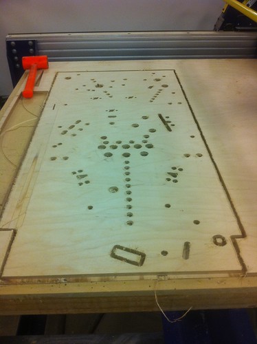
I couldn’t figure out why the Ball lane path is “etching” the non-lane wood. I tried a couple of things but they didn’t seem to make it better – only worse. So; I plan on leaving the 1/4” ball mill a little higher when it’s cut to try and avoid the etches.11/22/2013... this happened at techshop.ws:
![]()
I <3 me some CNCing.![]()
So yeah... me is happy:![]()
11/24/2013:
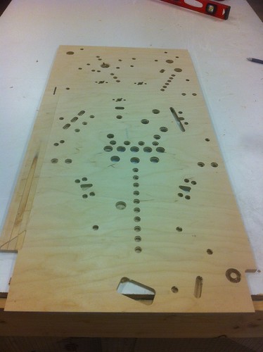
I had another 4hour block on the CNC machine at techshop... I finished up drilling the holes in the PF:
![]()
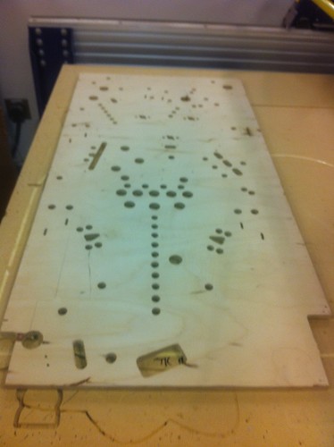
I also flipped the PF and CNCed out the proximity slots on the underside of the PF:![]()
I have about 7 hours total in the PF including setup and actual CNC time.
I cleaned the wood "fuzzies" from the top of the PF with a wire brush attachment on my dremel. There is currently Primer grey on the underside of the PF... trying to dry in this cold as$ texas night. Yes; I know your not suppose to paint below 50F... but I really don't have a lot of choice if I'm going to meet the TPF'14 deadline. -
Make It So: Table Art begins
04/01/2014 at 21:34 • 0 commentsLate 2012; I bit the bullet and got myself a Techshop.ws membership for the Austin/RoundRock location. While not cheap; I expect to make good use of the money spent.
For those that don’t know what Techshop is... in short it’s a “gym-membership” type of place which has over $500k in high tech machinery which the hobbyist can use once they’ve taken the required safety courses. Austin has a Waterjet, 2 shop bot CNC machines, mills, laser cutters, cnc sewing machines, tig/mig/welders, sand and powdercoating , etc.
For the last couple of years; I’ve been wanting to do my own pinball table. Those that know me... will already know the subject matter in question.
Late 2012; I settled on a plan.
Goal:
Create a Star Trek: Mirror Universe pinball table.
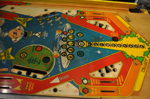
The plan; Scan in a 1979 Bally Star Trek pinball table. Mirror it. And customize it for the mirror universe.
Before (my previous PF/machine restore):![]()
![]()
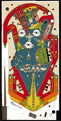
After: (click the picture to get a larger higher rez on flickr)![]()
Yeap; that’s right... the shooter lane will be on the left side (evil grin) and will have a negative feel. What has been done:
Re-colored the playfield; fixed worn areas (in computer). Then flipped the playfield.
Areas changed:
1) “vectorized” nearly all aspects of the PF.
2) removed “reversed” text and replaced with Star Trek: series font.
3) USS becomes I.S.S. Enterprise.
4) Space Station K0 becomes Battle Station K0
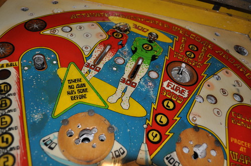
5) Transporting people become their “mirrored universe” counterparts complete with sashes and skin.
6) “enter Hyperspace” becomes “Avert Subordinate Promotion” “by thwarting and assassination conspiracy”.
7) “jump to warp” becomes “Employ Agonizer on Crewman”
8) “where no man has gone before” becomes:
“Your Mission: Conquer all worlds and civilizations to expand the empire like no man before”
(may be too wordy)
9) “Ready Photon Phaser” becomes “ready photon torpedo”
10) Spelling “bally” becomes “Terra” (Terra meaning Earth. Short for “Terran Empire”; the mirror universe’s “federation”)
11) Removed same player shoots again language; opting for “shoot again” text over insert.
12) Drop Target Special becomes Terran Empire logo.
13) colorized planet with purple glow like the re-mastered series from cbs. Not sure I like it... may go back to original look.
To do:
A) Still need to decide on replacement text for Orbit. was: “Activate Transporter Welcome Aboard”
B) Want to put some simple-ish graphic over 5000/500 advance bonus lanes.
C) convert PF to DXF to enable toolchain to Shopbot CNC.
You’ll note that I’ve removed all the switch lanes from the design. The plan is to design a set of hall effect pcbs which replicate functionality without slots in the PF.
Star Trek: The Mirror Universe Pinball
A custom / unique pinball machine. This is a 1978 Bally Star Trek table “mirrored” and re-worked into a Star Trek Mirror Universe Theme.


