ajlitt
Stop. Don't.
Bitcraze has open sourced all their hard work, which is what make this project possible. The Crazyradio PA is inexpensive compared to the Crazyflie itself. It's a lot of work to save $30 and end up with no better range than BLE.
So why did you?
I had placed an order for a Crazyflie 2.0 and didn't realize that I should have grabbed a Crazyradio PA at the same time to open up some functionality. I thought it would be a quick hack to turn the receiver into a low power Crazyradio. That way I could play with one before I have a chance to order the real deal.
Hardware
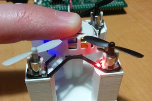
This is the donor mouse. It still works, and at some point I'll replace the receiver. But for now a sacrifice is required.

I cracked open the shell to see if there were any test points exposing the SPI interface and required PROG pin:
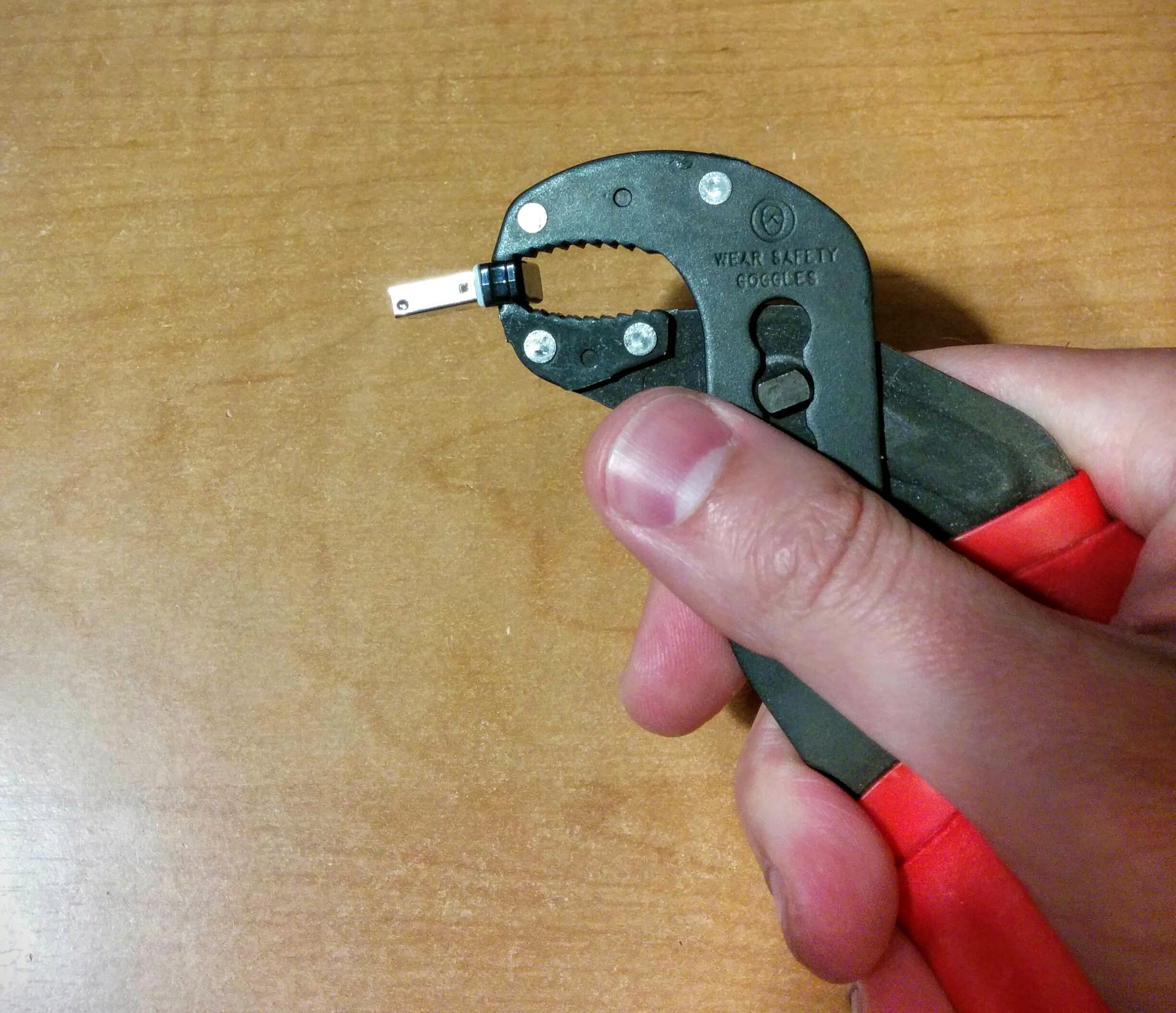
A little squeeze from a pair of pliers and the glue holding the cap to the body cracks.

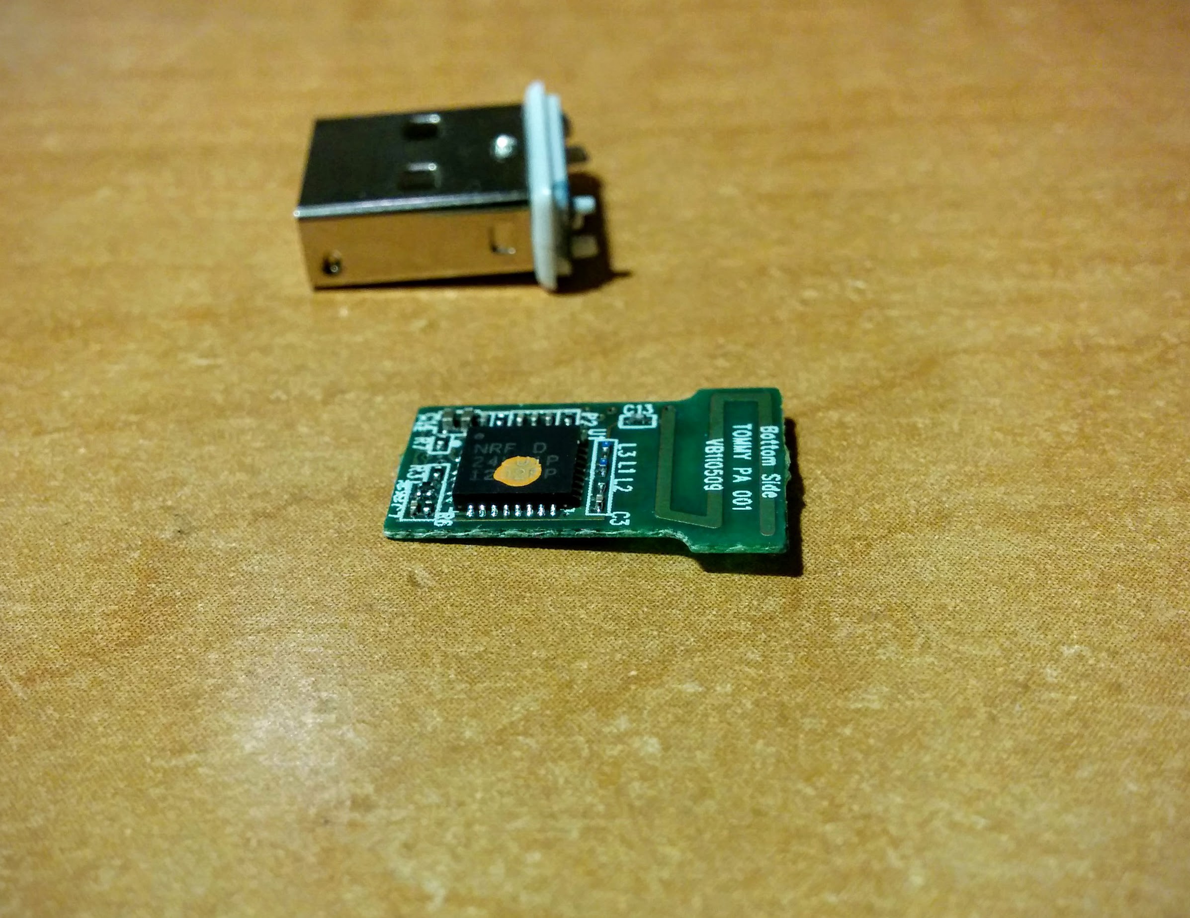
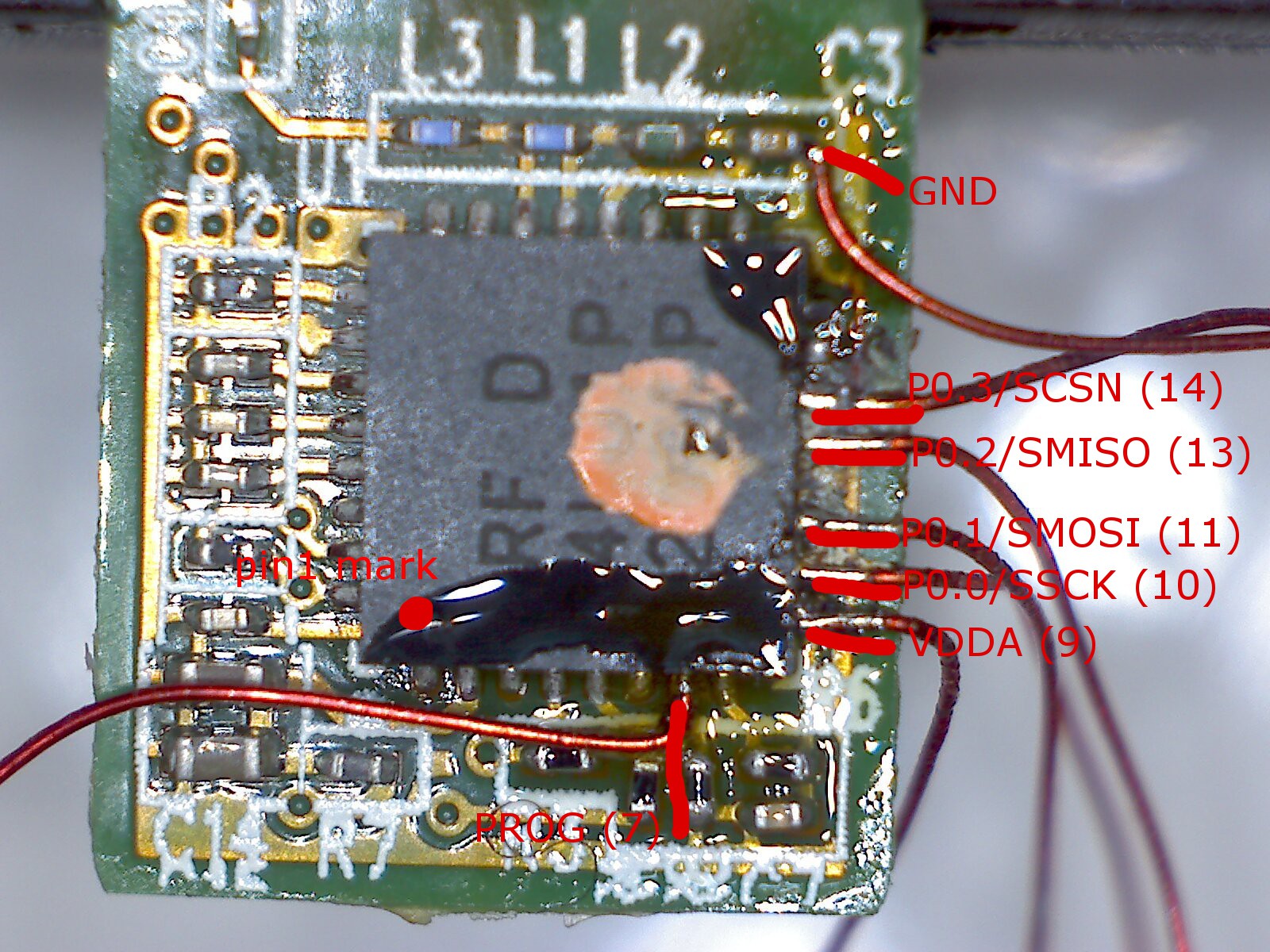
As you can see, no test points, just discretes and the chip. The orange dot is a dead giveaway that part or all of the firmware was programmed before the chip was soldered on the board.
I checked the pinout of the datasheet, and beeped out a few pins. The SPI port, VCC, and ground are all available on the edge of the package facing the camera above, while PROG is on one of the resistors to the bottom left. Fortunately the SPI port pins are unconnected. Unpleasant, but not impossible with some magnet wire.
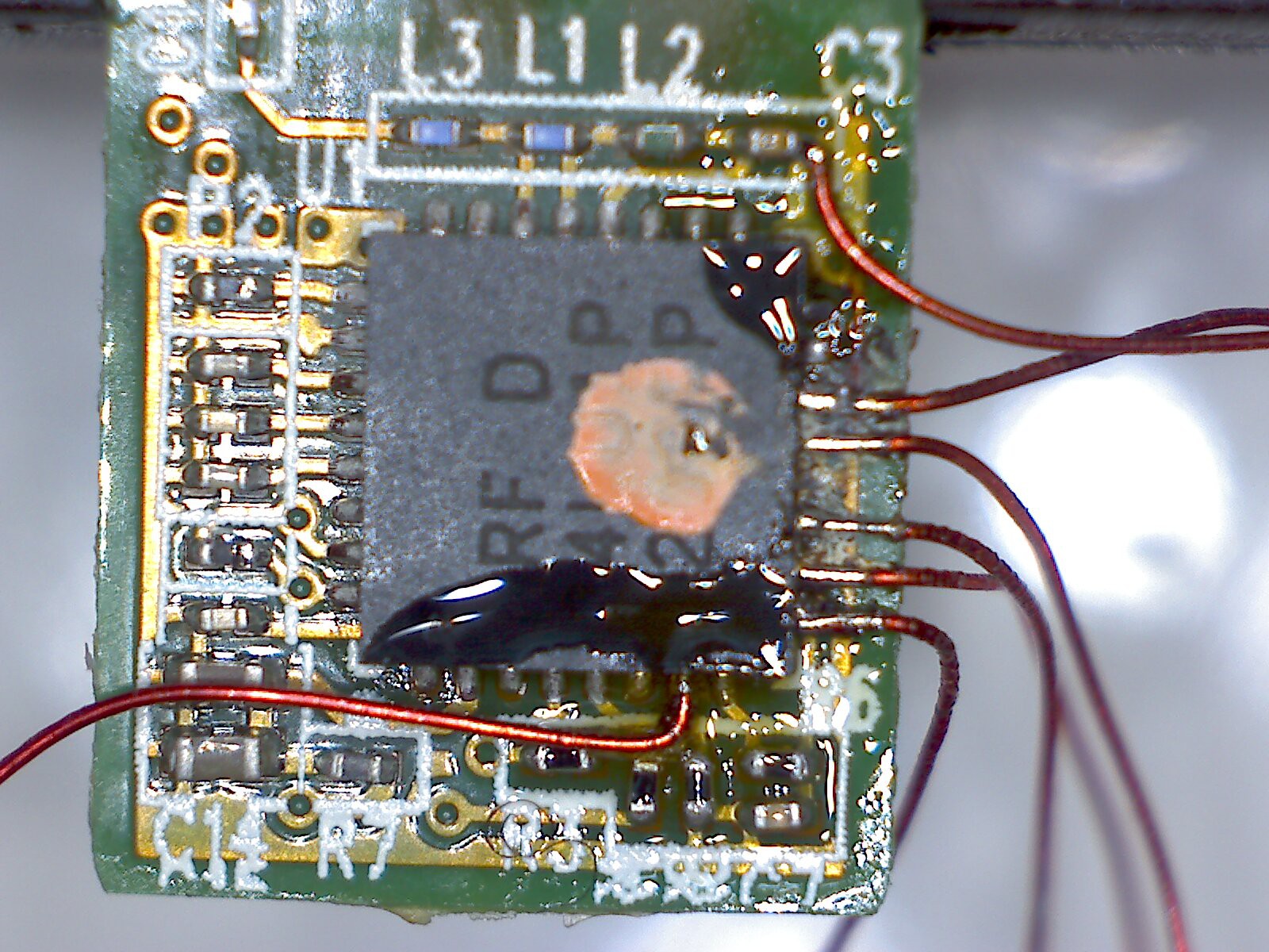
This went much faster than you might expect. Magnet wire is designed so that solder cooks off the enamel insulation. So by carefully tinning the tip of the wires and using plenty of flux on the PCB, it's easy to solder small targets like QFN feet.
My iron has a 1/16" chisel tip, which is great for cozying up to the tiny exposed QFN pads. To keep from desoldering neighboring wires, I tacked wires down the edge with the SPI port sequentially. With good lighting I didn't need a microscope during soldering, though I used my cheapo USB magnified camera to inspect the work afterwards. I ended up picking off GND from a bypass cap since the ground plane at the QFP lead was too heavy to solder in those close quarters, but everything else was soldered to the QFP.
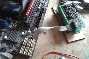
With all the wires in place I used double stick tape to hold it tight to a breadboard. The tape was unexpectedly helpful in holding the wires as a sort of strain relief. I ran the free ends of the wire perpendicular to pins on a header I put on the board, tacked each lead, and trimmed them.
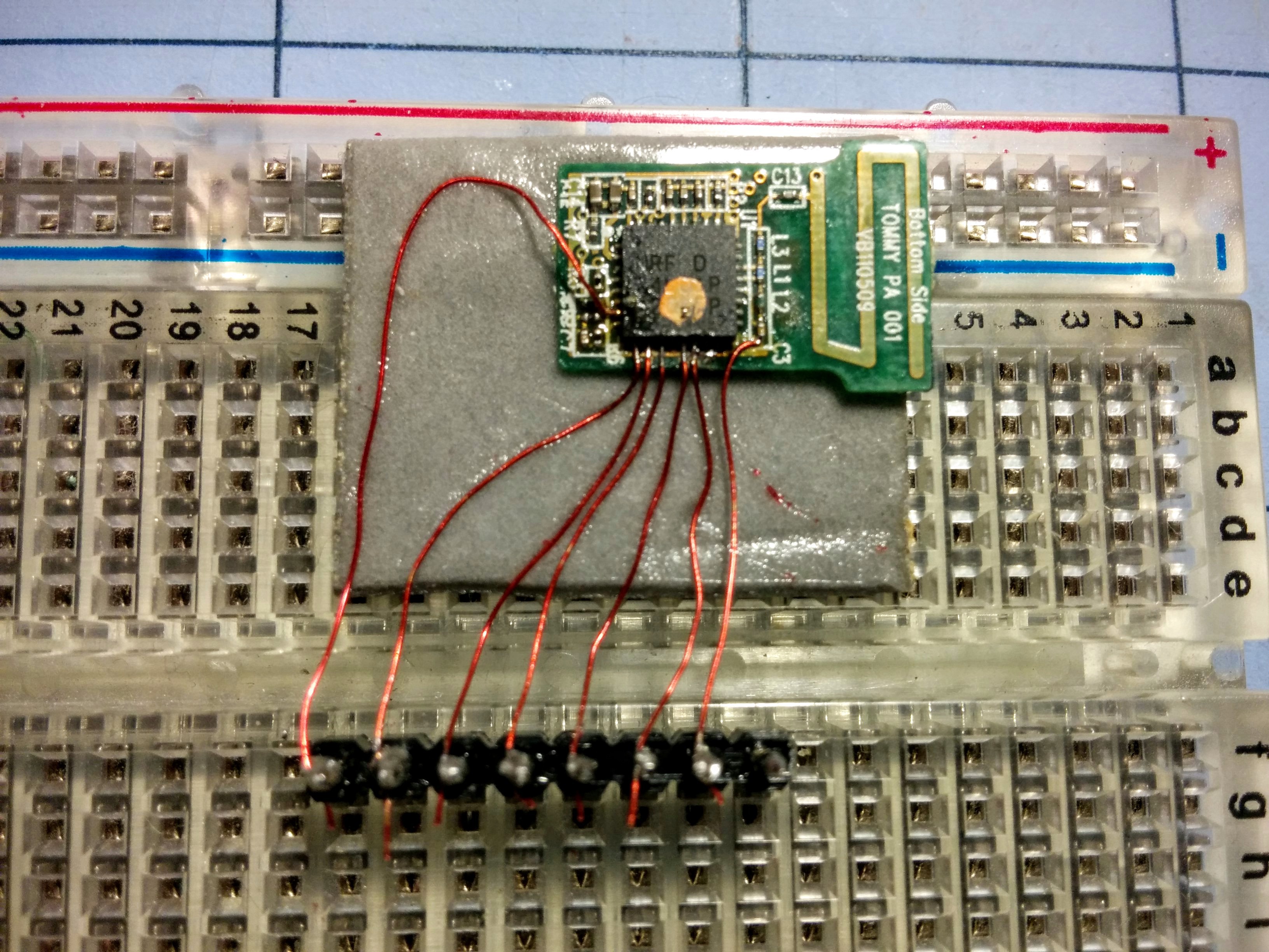
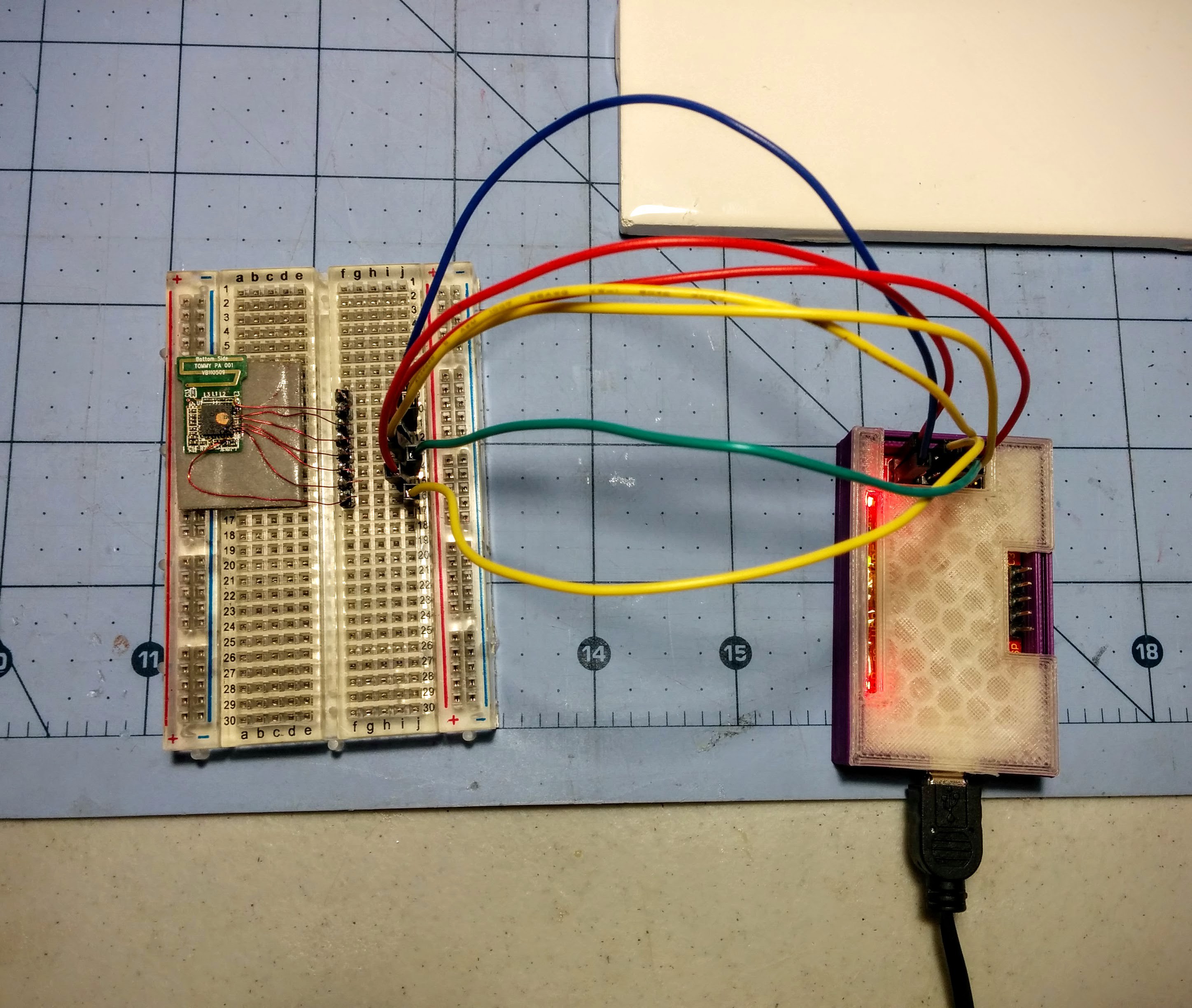
I then followed the wiki to wire each signal to a pin on a Bus Pirate.
This took about 45 minutes from start to finish for the hardware work.
Software
I started out with the buspirate_nrf24lu1 project on Github. This is the script Bitcraze recommends on their wiki for recovering a Crazyradio with a Bus Pirate. buspirate_nrf24lu1 is a Perl script that works on OSX or Linux (after cpanning Device::SerialPort) to erase the nRF24LU1 and write a binary blob to flash.
Before I cracked apart the dongle, I looked at the GPIO and peripheral requirements for Crazyradio. There are only a few GPIOs on the nRF24LU1+, and Crazyradio only uses two for LEDs (Crazyradio PA uses an extra one for controlling the amp). The dongle uses none of the GPIOs, so it looked like it should work without any changes.
My first attempt at running this seemed to work, but complained about the status register being incorrect (0x24 and not 0x20) before erasing. The datasheet decodes this to WREN and RDISMB set, with WREN being expected (enable writes, since it's about to do an erase) and RDISMB informing that the main flash space readback is disabled. Although this shouldn't hurt Crazyradio, I didn't want to take any chance that could only be fixed by soldering to the SPI port again.
I added commands to erase the infopage, a separate flash space for unique configuration data. The field that locks reads and writes to certain memory spaces lives here. That seemed to fix the error message, and the flash of the firmware binary in the repo completed after 5 minutes....
Read more »

 charliex
 Arya
Arya