 ajlitt
-
1Step 1
WARNING: there is no turning back. After running the flash script the original Unifying Receiver firmware can't be restored.
-
2Step 2
Separate the black plastic cap from the white plastic frame. Lightly crimp the cap with pliers while pulling. The radio module slides out.
-
3Step 3
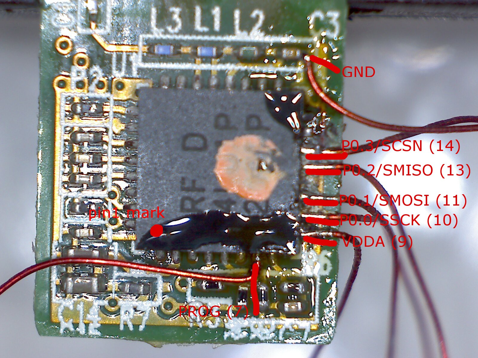
Flux the pads to be soldered, then tin and tack magnet wire to these pins:
![]()
-
4Step 4
Use double-stick tape to secure the board and each wire to the breadboard. Place the board on the tape so there is ample space for the adhesive to grab onto the wires.
-
5Step 5
Stick a 7 pin 0.1" header in the breadboard below the board. Pull each wire tangent to a pin on the header, and secure it with solder. Use enough solder and hold the iron so it cooks through the insulation. Trim the remaining ends when done.
-
6Step 6
Connect header pins between the Bus Pirate and receiver like this:
Bus Pirate pin nRF pin nRF Signal 6 7 PROG 2 9 3.3V / VCC 7 10 SSCK 8 11 SMOSI 10 13 SMISO 9 14 SCSN 1 GND (from cap) GND -
7Step 7
Get the files from the github repo:
git clone https://github.com/al177/buspirate_nrf24lu1p
This has only been tested on a Linux host...
-
8Step 8
Plug the Bus Pirate into the PC and determine the device (usually /dev/ttyUSB0 if nothing else is attached).
-
9Step 9
Run the script as root (or whatever user has permissions for the port):
sudo perl ./flasher.pl -input boot24lu1p-f32_padded.bin -device /dev/ttyUSB0
If this fails immediately complaining about Device::SerialPort, install the Device::Serialport module from CPAN and try again. -
10Step 10
Watch for the first minute that no warnings are printed. If there are any warnings or crashes, check all the wiring. If it makes it past the erase stages, it should run to completion.
Go watch a movie. This is unnecessarily slow.
Crazyradio for Cheapskates
Turning a wireless mouse USB adapter into a quadcopter transmitter
Discussions
Become a Hackaday.io Member
Create an account to leave a comment. Already have an account? Log In.