John
John-
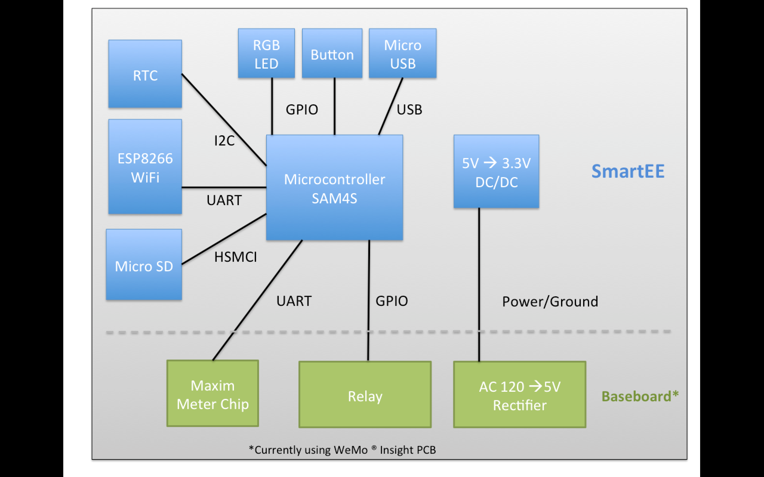
System Block Diagram
08/15/2015 at 01:01 • 0 comments![]()
-
SmartEE in Action
08/12/2015 at 21:22 • 0 commentsHere's a short demo video of SmartEE in action.
Here the plug is connected to standard incandescent lightbulbs on a dimmer. The software interface is [wattsworth] (a larger power monitoring project that should be released later this year). Using the python libraries with SmartEE makes it easy to add smart plugs to any project.
The github repository has 3 folders- covering each section of the project
- Hardware: Schematics, PCB layout, gerbers, and BOM
- Firmware: Code for the SAM4S. Check out the compilation instructions in the project log.
- Software: Python modules for incorporating SmartEE plugs into your own projects.
As always, please let me know if you have any questions!
-
Using SmartEE
08/12/2015 at 21:15 • 0 commentsSmartEE uses a simple text based protocol on port 1336. You can access it directly over telnet but the easiest way to integrate it into your project is to use the python module [plug.py]. This module encapsulates a plug object and provides direct methods to read data, erase the SD card, set the RGB LED, and of course turn on and off the relay. It can be directly incorporated into any Python project with minimal dependencies. You need [sockets] for TCP/IP communication, and [serial] for USB communication. There is currently a dependency on [numpy] for the data processing but this isn't strictly necessary. However, most projects manipulating power data will probably want numpy anyway.
[demo.py] facilitates shell scripting applications and to demonstrates the usage of [plug.py]. Running [demo.py] with the help flag shows the documentation and example commands:
usage: demo.py [-h] [--relay {on,off}]
               [--read] [--usb] [--erase]
               [--file FILE] device

demo.py
    John Donnal 2015
    GPL v2 (see LICENSE)

    This demonstrates some of the capabilities of the SmartEE plug control board

    Usage:

    1.) Control plug relay:
        python demo.py --relay on  192.168.1.4
        python demo.py --relay off 192.168.1.4
    2.) Read meter over WiFi, appending to a
        data file
          python demo.py --read 192.168.1.4
    3.) Download data over USB, appending
        to a data file
          python demo.py --read --usb /dev/ttyACM0

    Data files created by this script are
    CSV formatted with the following columns
 ts | vrms | irms | watts | pavg | pf | freq | kwh

    ts   | timestamp (UNIX milliseconds)
    vrms | RMS Voltage
    irms | RMS Current
    watts| Watts
    pavg | 30 second average of watts
    pf   | Power Factor
    freq | Line Frequency (Hz)
    kwh  | Energy used since plugged in (kWh)

-----------------------------------------------------

positional arguments:
  device            Device: either a /dev/NODE
                            or an IPv4 address

optional arguments:
  -h, --help        show this help message and exit
  --relay {on,off}  Set relay state
  --read            request meter data
  --usb             plug connected by USB,
                    specify device node,
                    *not* IPv4 address
  --erase           erase data after reading
  --file FILE       destination file for meter data
These files are in the [software] directory of the git repository. Check it out! - and of course if you have any questions please let me know!
-
The Firmware is Yours
07/29/2015 at 17:53 • 0 comments![]()
The github repository now has all of the SAM4S source code under the firmware directory. Here's how to build it:
- Install the arm gcc toolchain (arm-none-eabi). This can be done easily with your distro's package manager
- Download the ASF library into a folder named [asf] inside the repository (on the same level as [inc] and [src]). You can download it here (free account required), and documentation can be found here.
- To compile the code simply run make. This should create a [bin] directory with the binary to flash to the SAM4S.
- For convenience the additional target [make gdb] can be used if you are using the Black Magic debugger. This automatically downloads the code to the chip and starts a GDB session. Before you run this make sure you authorize the .gdbinit file in the repository (if you don't GDB will complain and give you instructions on how to do this).
- By default the SAM4S boots the SAMBA bootloader code. To switch the chip to boot into flash (ie. run your code) set GPNVM bit 1. This can be done easily with the Black Magic probe in GDB:
Loading section .text, size 0xd564 lma 0x400000
Loading section .ARM.exidx, size 0x8 lma 0x40d564
Loading section .relocate, size 0xa7c lma 0x40d56c
Start address 0x407970, load size 57320
Transfer rate: 39 KB/sec, 939 bytes/write.
(gdb) mon gpnvm_set 1 1
GPNVM: 0x00000002
(gdb)
Please let me know if you have any questions! Happy smart plugging!
-
Designing the Firmware
07/24/2015 at 21:19 • 0 commentsDesigning stable firmware for embedded devices is always more complicated than it first appears. The goal with this project is simple - read the solid state meter and toggle the relay ON and OFF over WiFi. Should be easy right? Well....
![]()
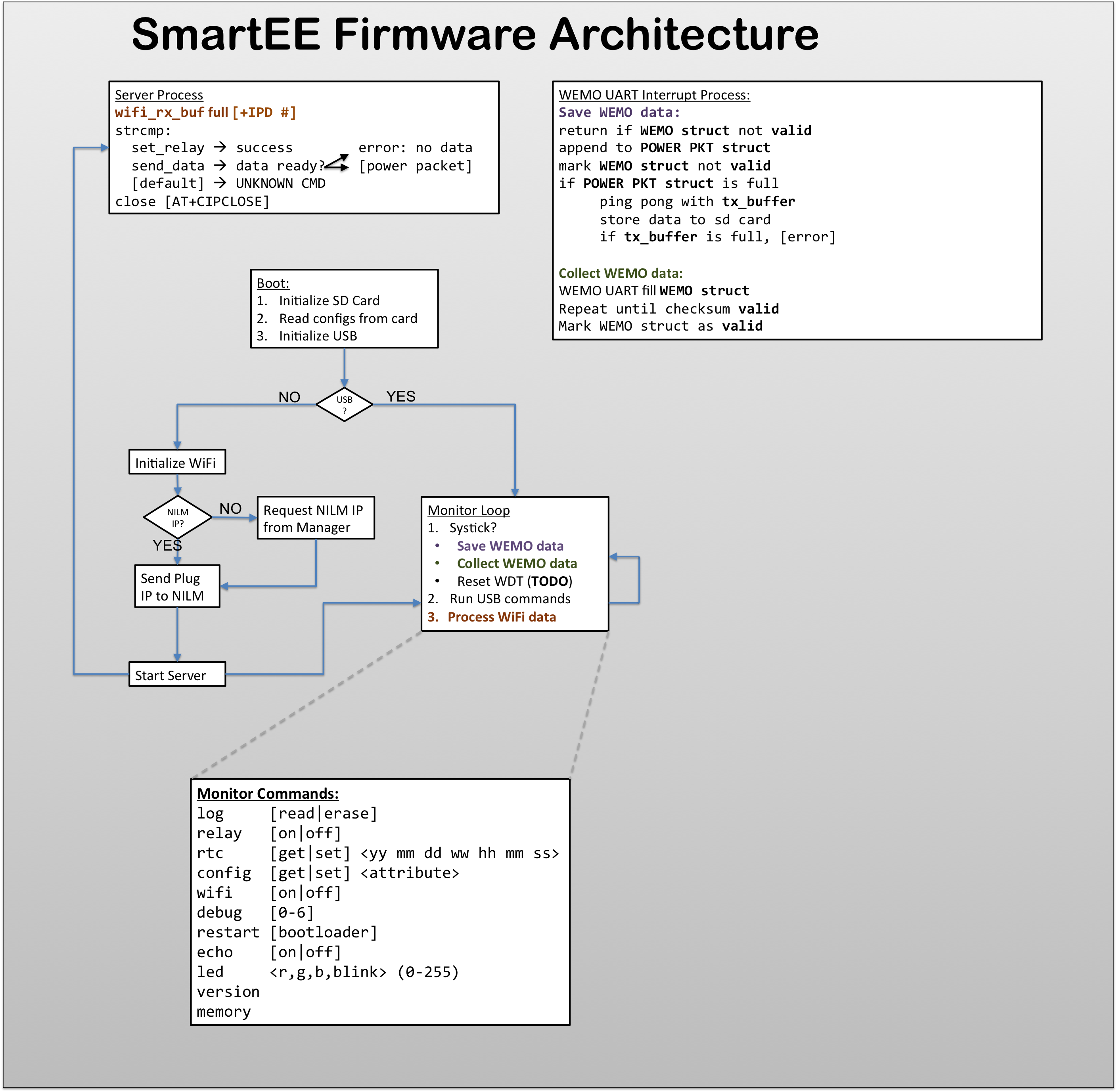
There are three main modules: WEMO interrupt, Server Process, and Monitor Loop
- The WEMO interrupt module records values from the solid state meter. The most recent samples are kept in a buffer and then stored to the SD Card.
- The server module listens for TCP traffic on port 1337 (woot!). Incoming traffic is parsed and if a valid command is received the module executes the request (eg. turn ON relay).
- The monitor loop provides a common systick for the other modules, coordinates their execution and handles USB TTY commands when the board is connected to a PC.
WEMO Interrupts
The solid state meter auto reports data quite fast - several packets per second. This is too much to transmit so only one packet every other second is actually recorded. Sampling at 0.5Hz seems to be a good tradeoff between resolution and WiFi bandwidth. Each time the monitor loop runs it checks if a valid meter packet has been read, if a new packet is ready it is stored in the server buffer and also recorded to the SD card. The monitor then sets up the UART for a new meter reading. Since the meter chip sends data asynchronously to the monitor, the UART might receive a garbled packet depending on when it starts to listen. Fortunately garbled packets can be detected by their corrupt checksums and discarded.
Server Process
The ESP8266 uses AT modem commands which, while simple, are surprisingly tricky to handle in C. Manipulating strings and handling the asynchronous arrival of data requires some careful coding. Oh memory leaks.... The ESP8266 commands are all in [wifi.c] safely abstracting to gory details of AT commands from the rest of the code. Hopefully this will also make it easer to replace/upgrade the wifi portion of this build in the future.
Monitor Loop
The monitor loop is the main [while(true)] loop that coordinates the execution of the other processes. Additionally it handles USB TTY commands which are used to configure the plug and retrieve data. The figure shows some of the supported commands.
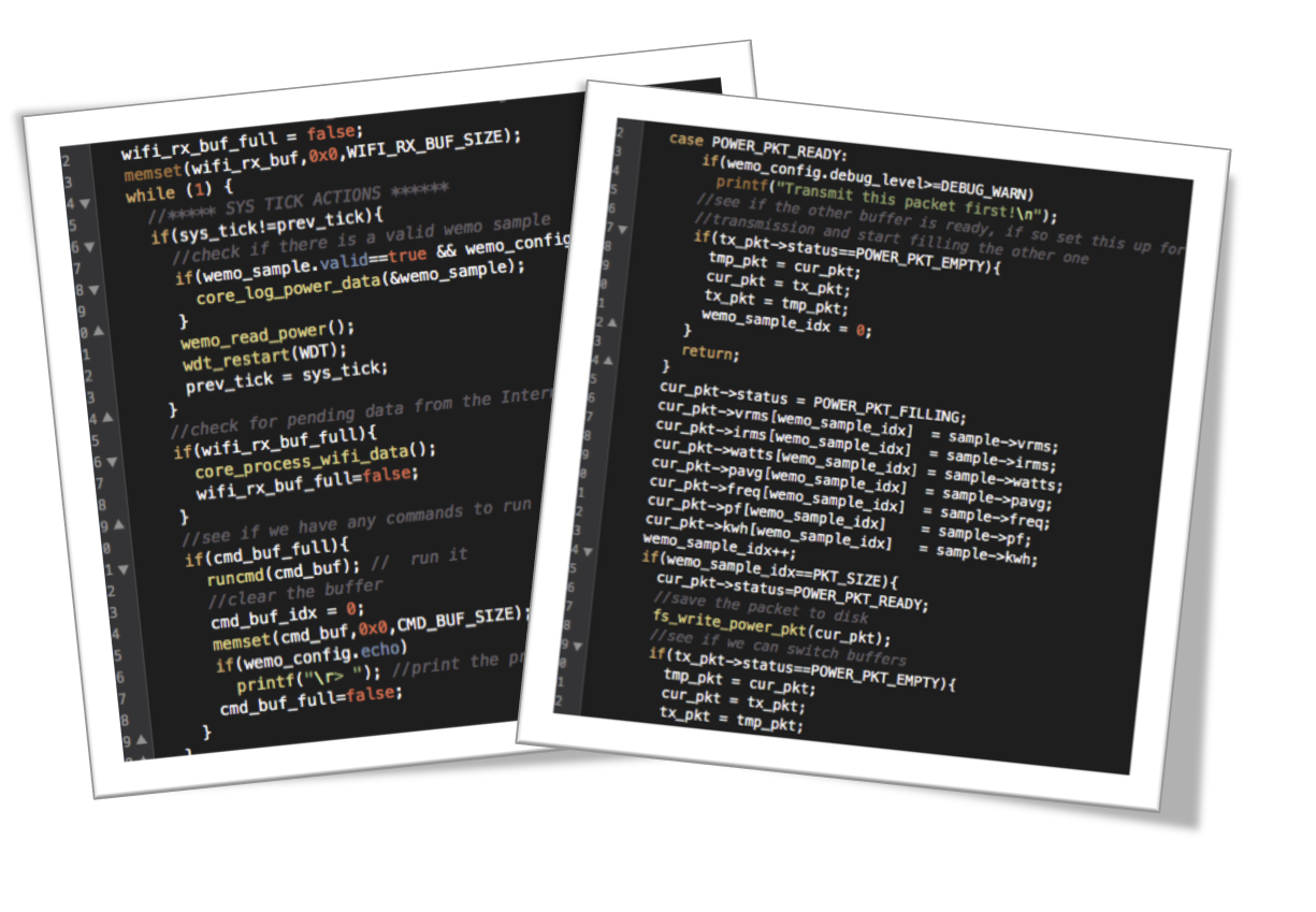
Of course you can only really get a feel for the code by looking at the code! I'll be posting the full firmware to the github repository soon!
If you have any questions please let me know!
-
The Hardware is Yours!
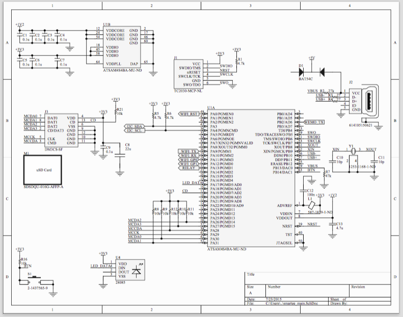
07/23/2015 at 19:50 • 0 commentsThe github repository now has a [hardware] folder with all the schematic files and the PCB layout. The project is in Altium but don't fear- all of the outputs including assembly drawings, BOM, schematic PDF, and gerbers are in a dropbox folder linked with this project. All of the source is licensed under GPLv2 so enjoy! If you see any errors please let me know :)
![]()
-
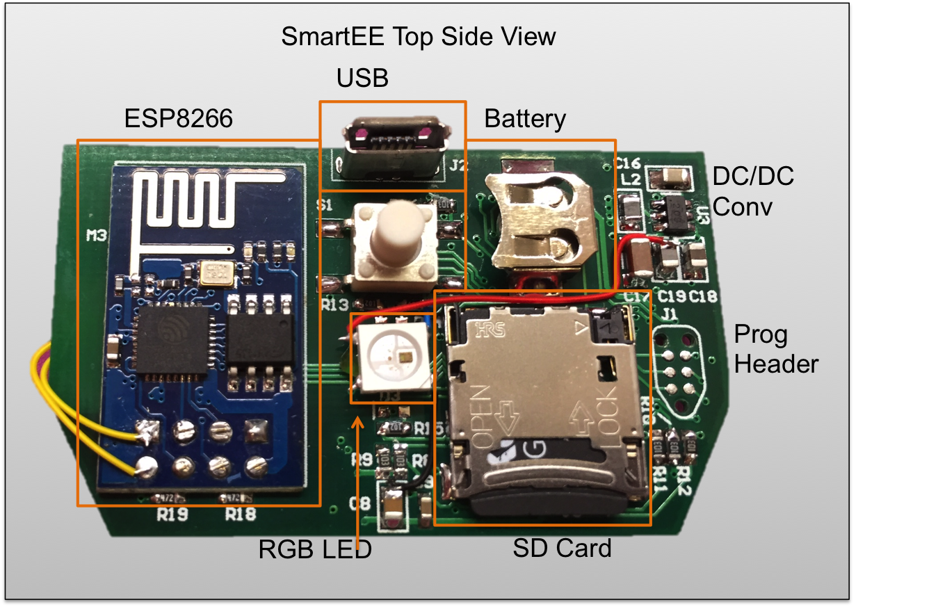
Hardware Design
07/21/2015 at 22:17 • 0 comments![]()
Now that we know the communication protocol between the WeMo(R) base board and the control PCB its time to design the custom controller. Of course the replacement has to maintain the same physical dimensions as the original and the I/O components need to be in the same places as well. Some Digikey searching yielded a compatible header connection, vertical USB port, and button. I opted for an RGB LED instead of the two discrete LED's that are on the stock board and I omitted the capacitive touch hardware mostly due to space constraints.
In addition to the stock functionality I've added some new features that make the plug much more useful in environments without good WiFi coverage:
- Long term storage so the plug can log data without a network connection
- Battery backed real time clock (RTC) so data samples are consistently timestamped
- USB interface for configuration (the original has a USB port but does nothing with it )
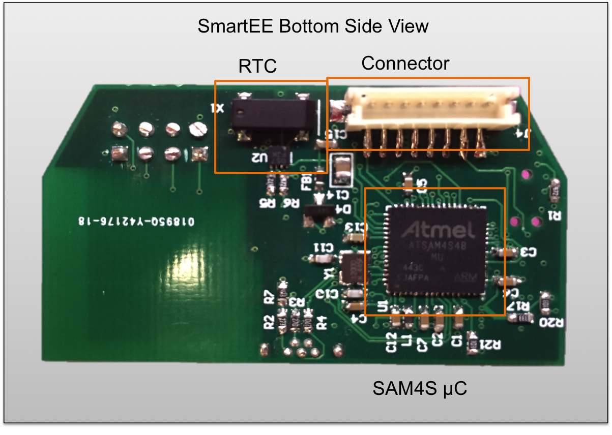
For storage you can't beat SD cards for size and cost so I threw in one of my favorite uSD connectors. Since there's going to be a fair bit of processing going on I opted for an ARM micro. Atmel's SAM4S is a really nice chip with plenty of peripherals including an HSMCI interface for the SD card. Its also (recently) compatible with the sweet black magic probe which makes development much nicer in a Linux environment -- although I've had good experience with Atmel's IDE as well.
![]()
The RTC is nothing special- just your vanilla I2C device with a coin cell for backup. Cost and space constraints make nicer models like the DS3231 impractical, but it doesn't need to be extremely precise so this should be sufficient.
For the wireless network connection I'm using everybody's favorite ESP8266 module from SeeedStudio. Its cheap but the AT commands make things a bit difficult. I've also had some stability issues with the stock firmware. After upgrading them to the latest image I could find, they seem to work better. The upgrade process itself is rather confusing, but for less than $7 I can't complain!
![]()
From the pictures you can see a few errors I made on the first run, but a new rev is in the mail so hopefully no wire-wrap connections next time!
-
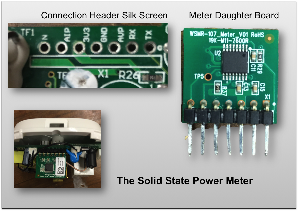
Some Detective Work
07/20/2015 at 16:16 • 0 commentsThe WeMo (R) plug provides two basic capabilities: switching a load on/off, and monitoring the load's energy usage. The load switching is pretty straightforward, a standard 15 amp relay on the mains current path is connected to a GPIO line on the control board. Since the relay is, by design, isolated the control board can safely switch the load without using mains voltage.
Monitoring the load's energy usage is a more complicated affair. For this task, the WeMo(R) uses a dedicated daughter board with a solid state meter chip. Putting this on a separate board is probably motivated by space constraints and UL rules about trace width/separation for high current, high voltage lines. Removing the meter board shows a silkscreen which helpfully labels TX and RX pins (although RX is sadly not connected)
![]()
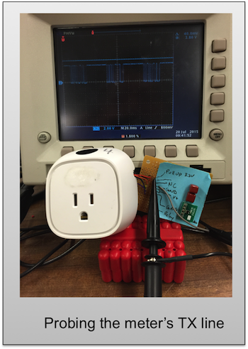
Packaging the WeMo(R) back together and attaching it to a scope shows that one of the wires on the control board harness is in fact carrying some data. The actual connection between the control board and the meter is a tricky affair. An optical isolator separates the two so the casual user would not notice the connection with a simple multimeter tone out.
![]()
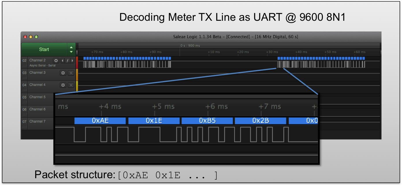
Of course the scope can only get us half way there. Switching over to a logic analyzer (I use a Saleae Logic) we can try decoding the signal. There are a few standard communication protocols: UART, SPI, I2C. The silk screen suggests UART since both SPI and I2C require a clock which is noticeably absent. UART's can have a variety of settings for baud rate, bits per frame and parity but fortunately the data pops right out using a standard 9600 8N1 decoding. Unfortunately the only consistent pattern seems to be the two bytes at the beginning of each packet [0xAE 0x1E] and the packet length of 30 bytes. The rest of the fields seem consistent over time which indicates they are probably measurements, but their values are hard to decipher.
After lots of tinkering with loads of varying power levels and even directly tweaking the AIP and AVP lines I still could not make sense out the data fields. Given that there was so much data (30 bytes) this must be quite a nice chip and probably doing much more than the stock WeMo(R) app was letting on. If only the WeMo(R) came with a datasheet....
Time for some detective work. The meter chip has 16 pins and some inscrutable markings - no manufacturer logo or other easy giveaway. Searching for 16 pin power meter chips on Digikey gives plenty of results. Looking through these data sheets for UART connections and the magic number 0xAE gives a clear winner- the 78M6610+PSU. This chip has an auto reporting mode that periodically sends UART data with a header byte of 0xAE. The data format of the auto report, detailed on page 25, specifies that the second byte is the packet length. Ah ha! 0x1E is hex for 30. Excellent.
![]()
The 78M6610 is no slouch, according to the datasheet:
"An embedded 24-bit energy measurement processor (EMP) and firmware performs all the necessary computation, compensation, and data formatting for accurate, real-time reporting to the host. With integrated flash memory, the 78M6610+PSU is a completely autonomous solution capable of storing nonvolatile data such as calibration coefficients and input configuration settings."
This is quite exciting- WeMo(R) really went all out with this guy. Unfortunately their app exposes only a small fraction of this chip's real power. All the more reason to make an open source controller! I googled around to see who else might be using this chip and imagine my surprise when I came across this press release. Of course I had no luck finding this document before I did my Digikey hunt, but using the keywords 78M6610 and Belkin it pops right up. Confusingly though, it claims the WeMo(R) uses the 78M6610+LMU which doesn't seem to have an auto-reporting mode and only comes in a QFN-24 package.
Both chips use the same processing core and overall are quite similar. A very large set of registers collects data that can be queried directly or a selected subset can be sent automatically. After playing with some loads and using the datasheet as a guide, I managed to figure out 5 of the 7 data fields:
Auto Report Data Fields:
=====================
0: ???
1: ???
2: Vrms         X 1000
3: Irms         / 7.77e-6
4: Watts        X 200
5: Pavg         X 200
6: Power factor X 1000
7: Frequency    X 1000
8: kWh          X 1000
To automate the process, I wrote a simple script to that parses the packet. Data fields are 3 bytes each and the packet is signed by a simple checksum. Checkout the SmarttEE git repository for the code.
The data appears to be signed integers translatable to normal units by a scaling factor (Irms is a bit odd though...). Here's were it gets really weird though- the 78M6610+LMU is the only chip with the kWh register. So maybe Belkin has a special deal with Maxim? Maybe I missed something? If you have any ideas please let me know!Stay tuned for more details.... (and more stuff in the git repo!)
-
Background
07/17/2015 at 14:09 • 0 commentsThe WeMo (R) Insight is a "smart plug" that allows you to monitor a particular appliance and switch it on and off over WiFi. Check out Belkin's Description for more details. Out of the box you can only talk to it with the provided app or a few third party tools like IFTT. Some people have tried software hacks to control this device, one of the best is Ouimeaux. After looking into these tools for a while I decided they were still too limiting. Additionally I had serious problems getting the devices on my wireless network and keeping them connected. A hardware fix was needed!
At first I was hoping a simple antenna replacement would solve the WiFi issues. Following the guide here, I switched out the stock PCB antenna with a custom "high gain" one. I never quantified the RF quality of either antenna but in a few tests the WeMo reported better reception. In general though, the wireless problems were still present. Most likely the antenna was not the problem...
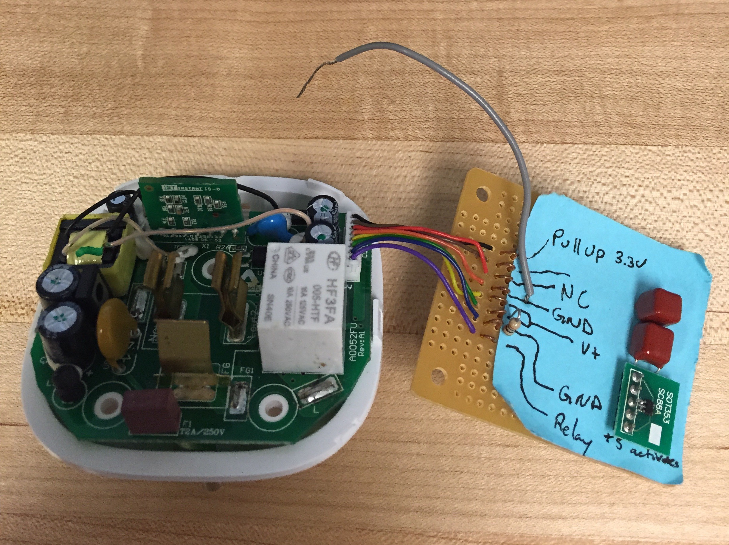
Time to crack the case open! After a few failed attempts and too much dremeling, I found the secret 3 triangular screws under the back sticker that keep the case together (see project instructions for photos). It turns out the device is composed of two separate PCB's. The high voltage components and solid state meter are on a "host board" and all of the smarts on a "control board". It was easy enough to attach some probes to the connector cable and figure out how the two communicated. ***DON'T TRY THIS WITHOUT THE RIGHT SAFETY EQUIPMENT*** So you don't have to mess with mains voltage, here's the connector pinout:
1: 3.3V Pull Up 2: UART TX (from solid state meter) 3: NC 4: GND 5: +5V 6: +5V 7: GND 8: Relay![]()
This is a great setup- the control board has an isolated +5V supply, a standard 9600 Baud UART connection to the solid state meter, and a logic level drive for the relay. What more could you ask for? The one trick is the 3.3V pull up on pin 1. The meter runs on its own isolated supply and an optical isolator connects it to the control board. In order for this to work the control board needs to supply a pull up to its side of the isolator, hence the LDO on the "sniffer board".
Stay tuned for more details!!