-
First time Surface Mount soldering
12/12/2015 at 17:12 • 16 commentsi finally got the ST chips I ordered from e-bay yesterday ( after over 40 days !!! ) .
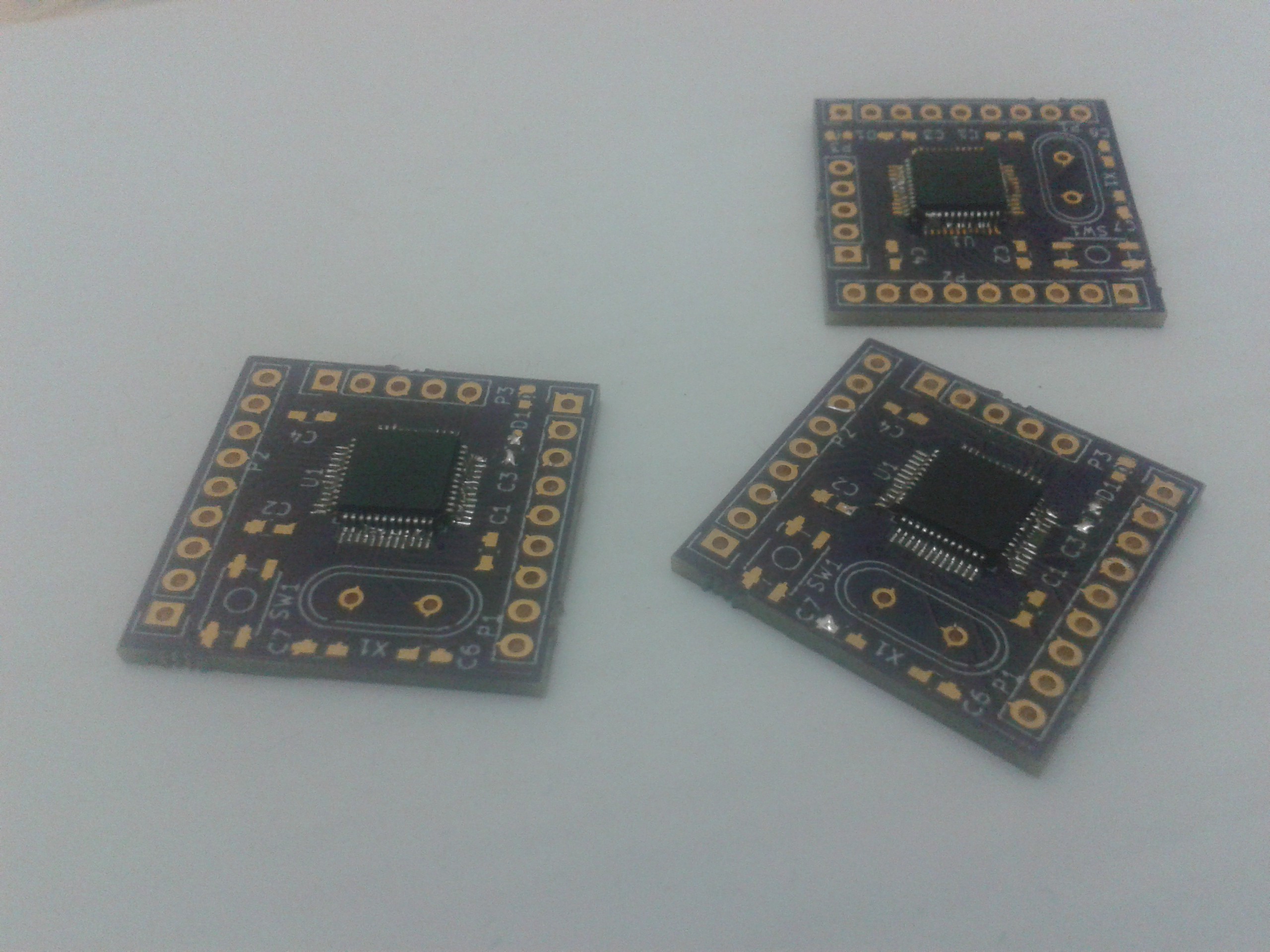
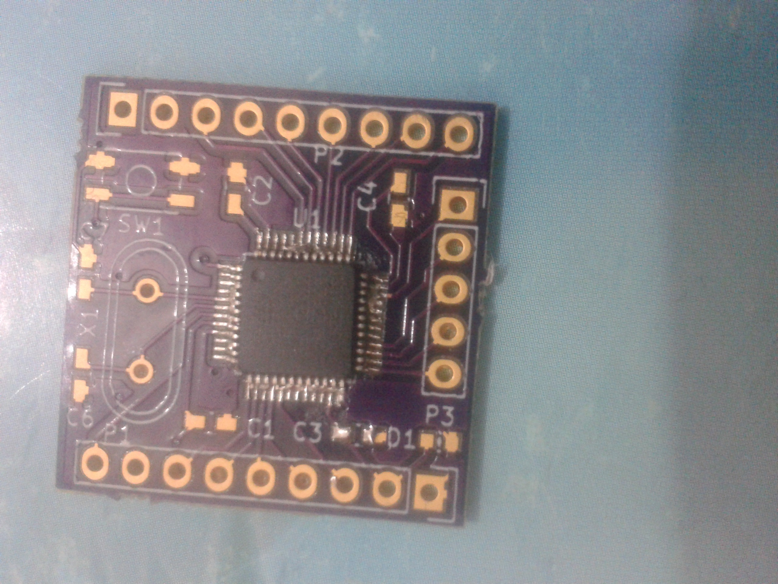
I went on and I tried to solder the LQFP48-package chips and indeed hand soldering these was a challenge. It's my first time as a hobbyist doing but I still mastered the courage to do it.
Results ??
Well it's not super clean and because I was unable to find solder wick in the near shop , I'm stuck with many bridges between the pins, at least untill the new stock is here.
![]()
![]()
Notes:
1) Solder wick is IMPORTANT.
2) Positing the chip was hard because some of the pins were out of place.
I will be working on a newer pcb version soon. I will also post updates about the current one , once i solder the rest of the stuff and I clean it.
-
PCBs from Oshpark are here !!!
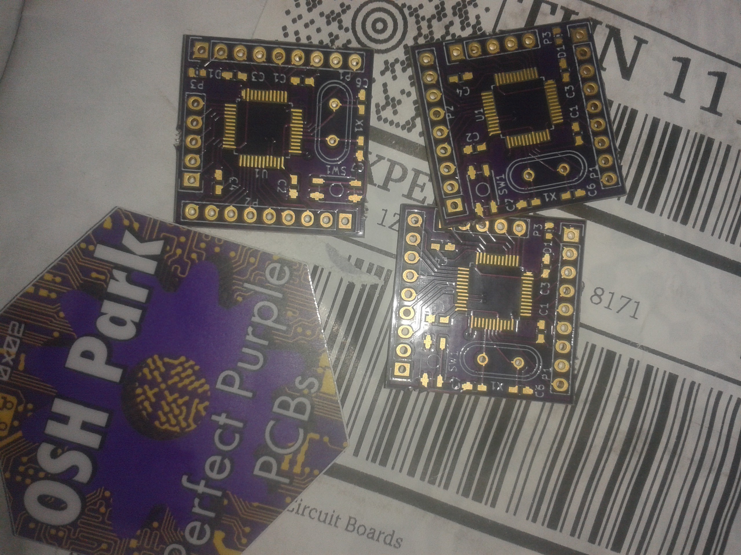
11/09/2015 at 15:59 • 0 commentsI just got the PCBs I ordered from Oshpark today and I must say I'm really impressed by how fast it got here.
![]()
I placed the order and it got automatically upgraded to Super Swift Service ( for free ! ) The boards were done within 6 days , shipped and It was here within 8 days ! Beauty , Thankx oshpark !!
About the PCBs:
These are breakout boards for the STM32F103CBT6 which I will be using for the next prototype. I ordered the MCUs from ebay and it should be here soon ( hopefully ).
These are the boards I designed for "The Square Inch Project". More updates soon.
-
New board Arrival
11/04/2015 at 19:08 • 0 comments![]()
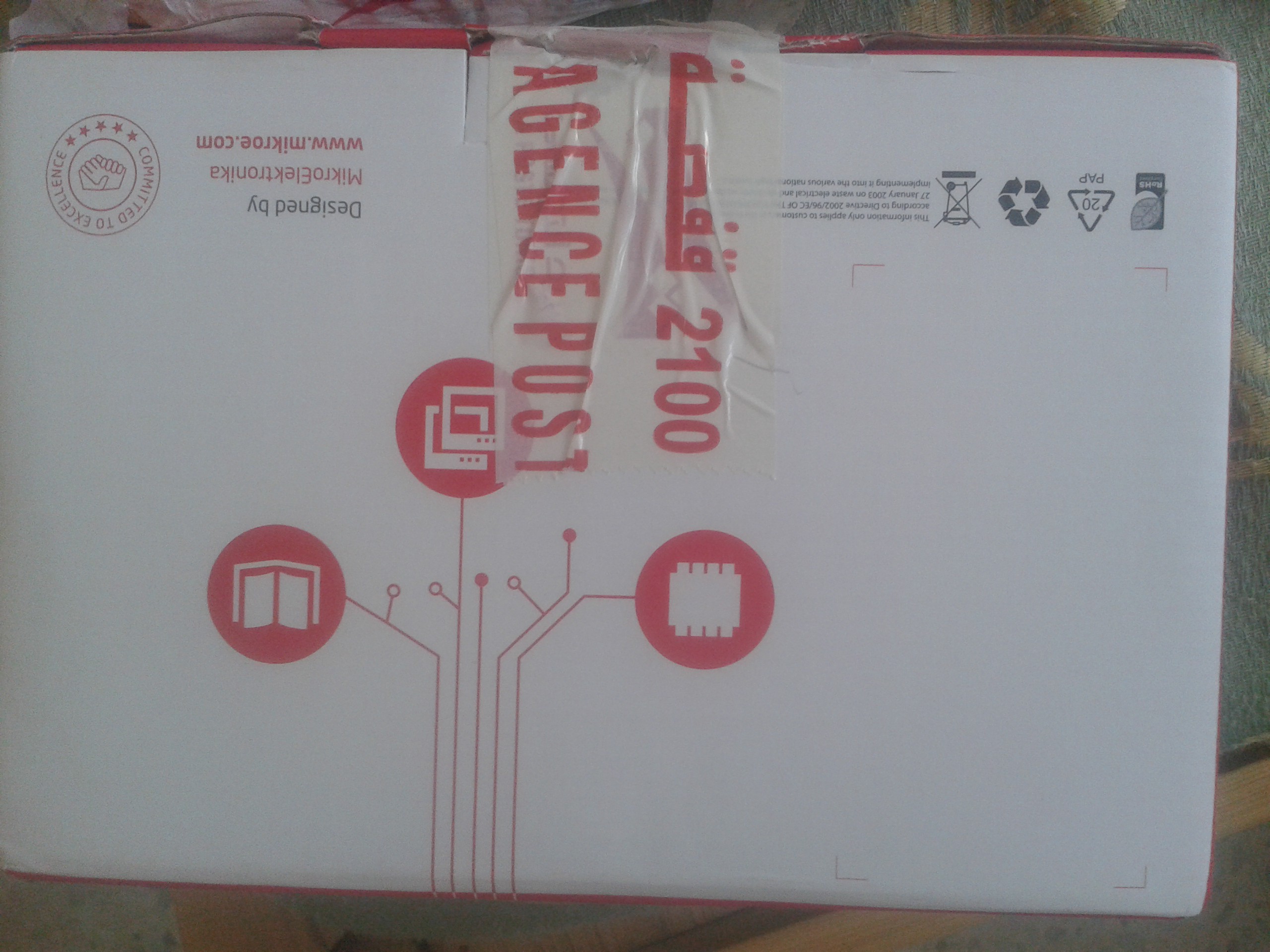
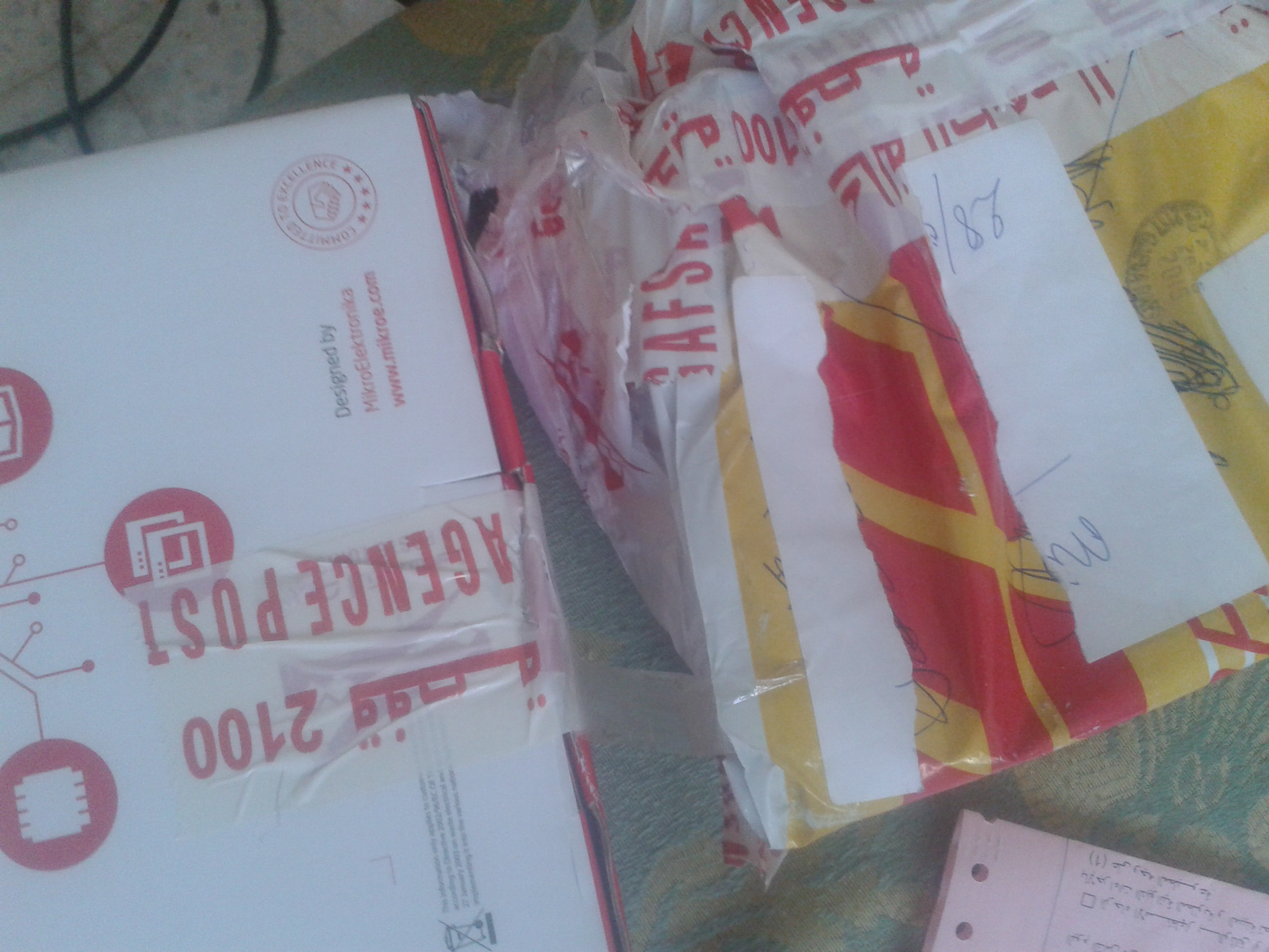
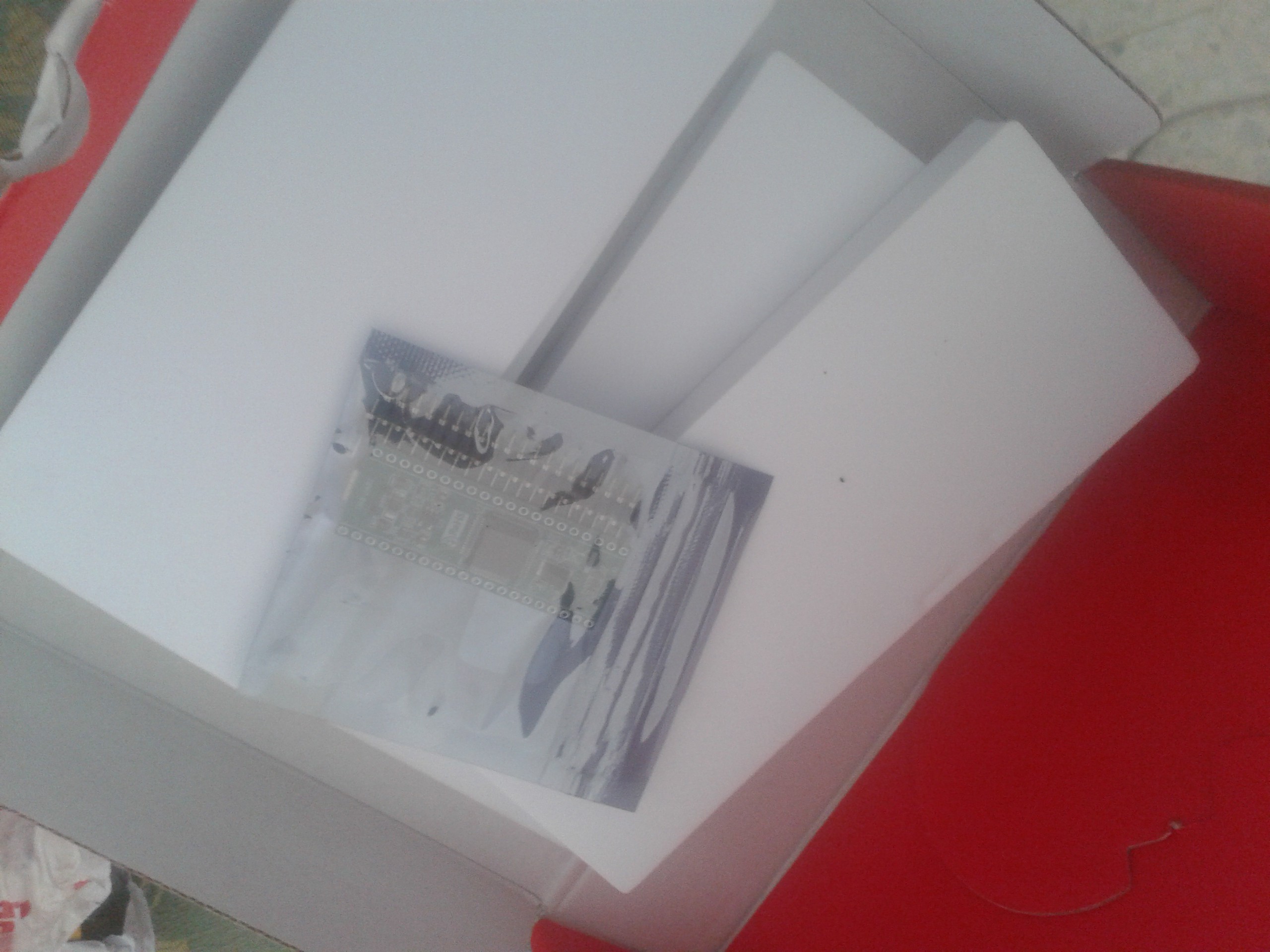
New board arrived. A "MINI-M0" from Mikroe.
![]()
![]()
A Quick unboxing reavels the board ( beauty ! ) . In the next log I'll be sharing the new prototype.
* Meanwhile I'm waiting for the new PCBs from oshpark *
-
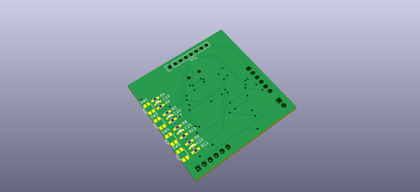
New Schematic Part 2
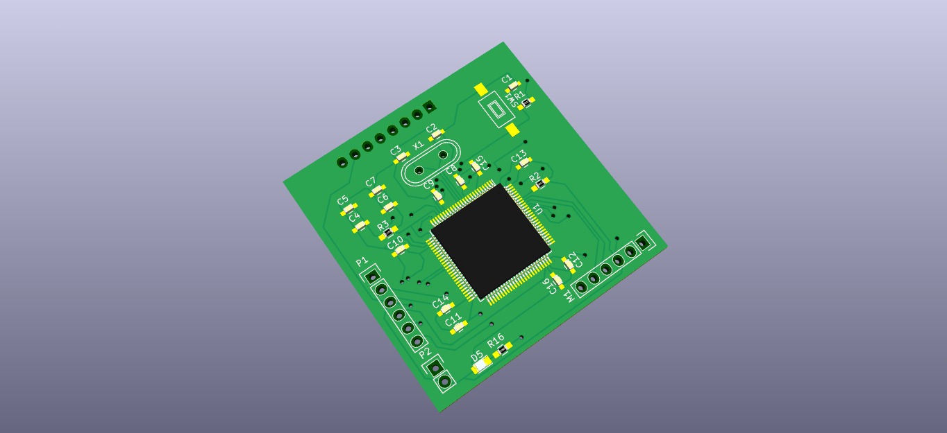
10/18/2015 at 07:51 • 4 commentsIn the previous update, I posted a new schematic of a custom board for this project based on the STM32F407VG ( obviously ) . Soon after I decided to edit go over it again and remove some parts which I thought I can replace the regulator & the usb port and replace it with a 2 pin header that will later on connect to one of these cheap/small modules for voltage regulation and battery control.
![]()
3.3V linear voltage regulator.
![]()
LiPo battery charging module from sparkfun.
I had 2 main reasons behind this decision : First is to reduce the work necessary to get this up and working later on & simplify the PCB design process as much as possible. The second is having these modules laying under the main board and reduce it height & width.
![]()
![]()
![]()
The Gerber files will be soon submitted to OSHPARK if no one points something odd on the schematic.
Currently in work:
I'm currently working on the website for this project. It's gonna be a place where I share all the resources behind this project including schematic files, source code.
-
Custom board 1: NEW schematic !
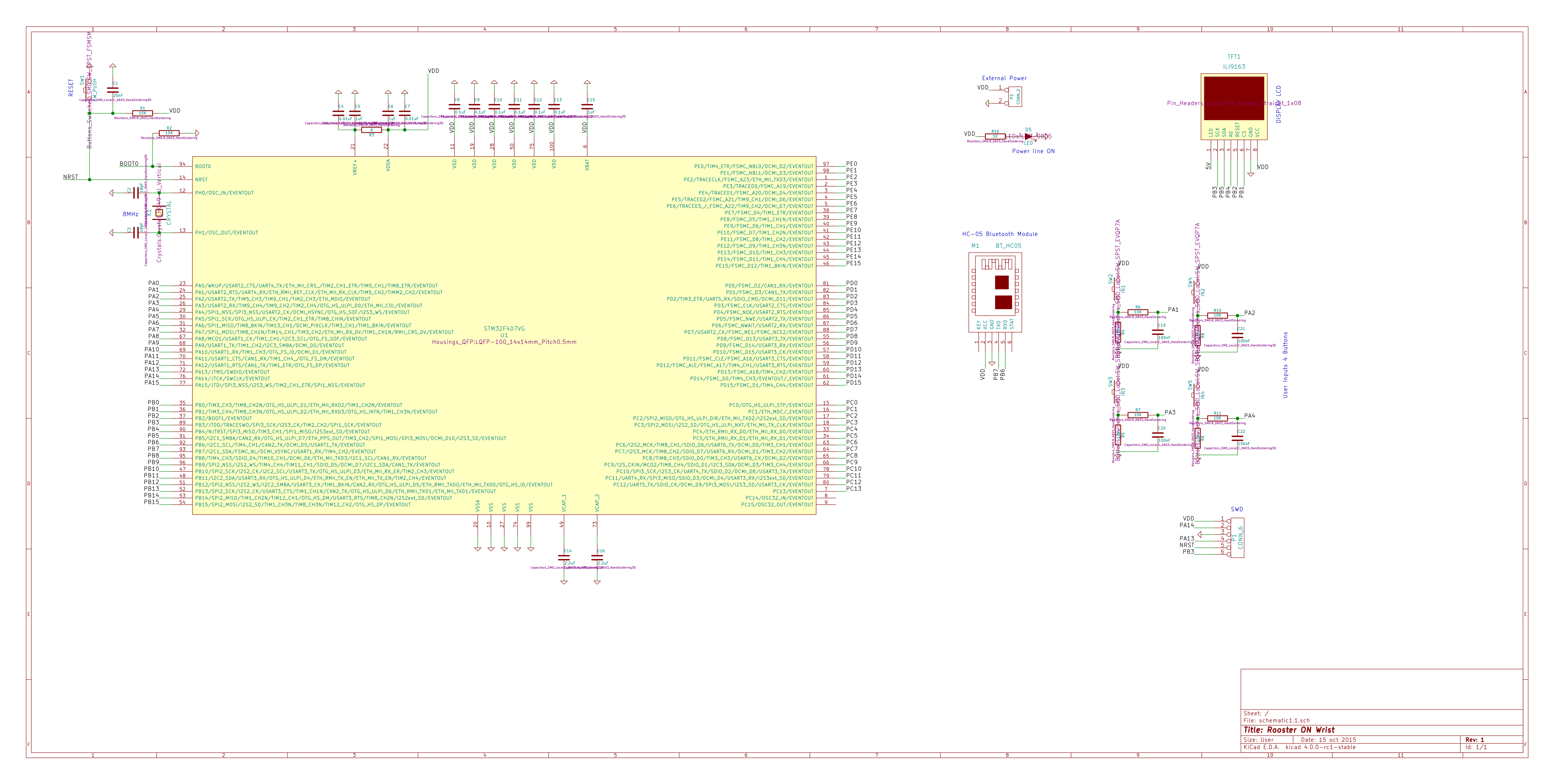
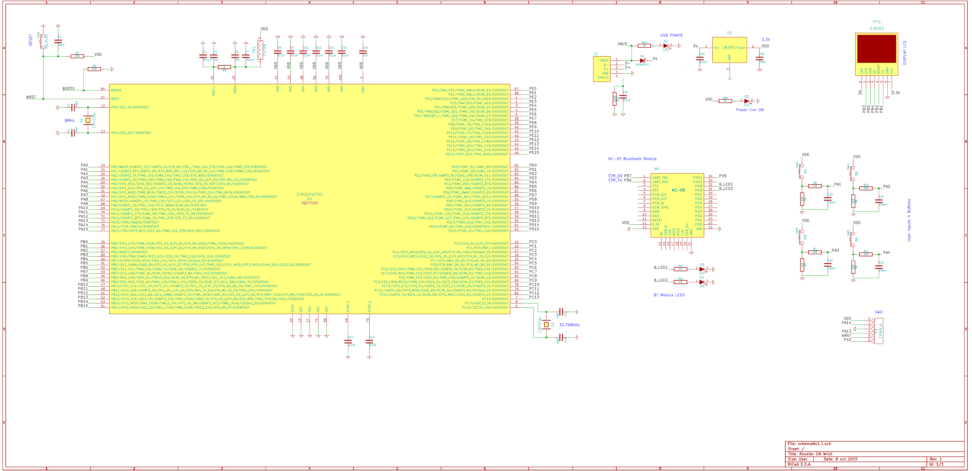
10/09/2015 at 16:31 • 0 commentsFor the last few days I've been working on the schematic for a custom board for this project.
I had to search other people who managed to make something similar and also made use of the discovery schematic as well. The following is what I came up with:
![]()
This was done with KiCAD. At first I was going to be using Altium's fairly new "Circuit Maker" which is a super cool piece of software but It required me to be coonect all the time which was not case.
Overall this was fun and I'm looking forward for anyone's feedback on this.
-
Gaming added to the watch with CHIP 8
09/03/2015 at 12:58 • 0 commentsBefore proceeding with the project log, let me thank all joined me in this and started following my project. I also apologize for not updating for a while.
Ok, few days ago I came across lots of emulation info while trying to write my own NES emulator in C++ . Unfortunately I couldn't write a NES emulator but, I found an easier target which was the CHIP 8. Everything went smoothly and I did that and that's when I got the idea of writing the emulator for the smart watch.
It was a super easy straightforward process that took me a day to write the emulator for PC and an hour to convert it for the smart watch.
I found this amazing tutorial for writing the emulator at http://www.multigesture.net/articles/how-to-write-an-emulator-chip-8-interpreter/ (You can read more about it there )
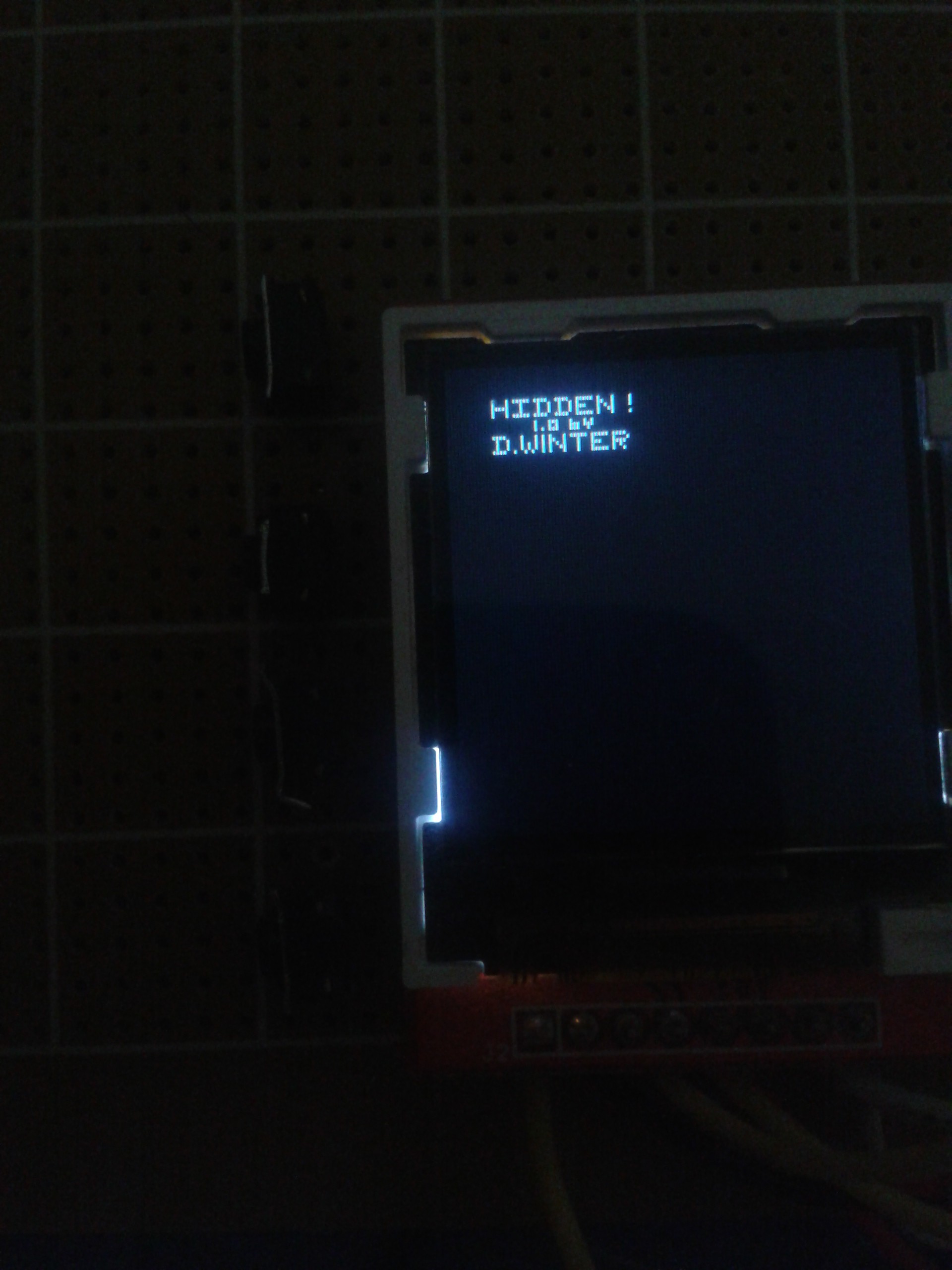
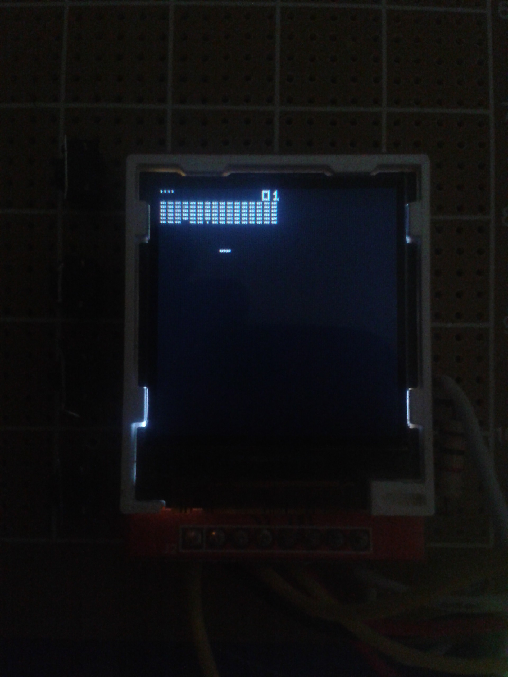
Game screenshots:
![]()
![]()
Brief notes:
- The games are included in the code but I can load them directly from an sd card if I implement the write code (which can be a future goal)
- The chip 8 outputs black and white graphics , the graphics are stored in an array (simulating the RAM in the actual system) as 0 (for back pixel) and 1(white pixel)
- Each pixel in the display array is output as 1 pixel on the smartwatch display and since the chip 8 is 64 * 32 , you can see why the games are taking a small portion of the screen ( I have to out put it as 128 * 64 in the next update )
- The CHIP 8 originally has 16 inputs for game play and all sort of control 1-9 & A-F .. However I have only 4 buttons on my smart watch , so that's another challenge.
- Clicking the top button on the watch toggles between the watch face and the emulator , you can clearly see it in the video above.
Conclusion:
So far the watch :
- Has a decent watch face with the weather/time/date.
- Displays notifications.
- Has games which can be loaded on the CHIP 8 Emulator.
Thinking outside of the box:
The emulator is good for games but it's not just limited to the games actually. Other programs can be written for CHIP 8 and with the right code it can be loaded to the smart watch over Bluetooth to achieve something like what the pebble has.
-
Added Buttons ,Animated Weather Icons & Notifications
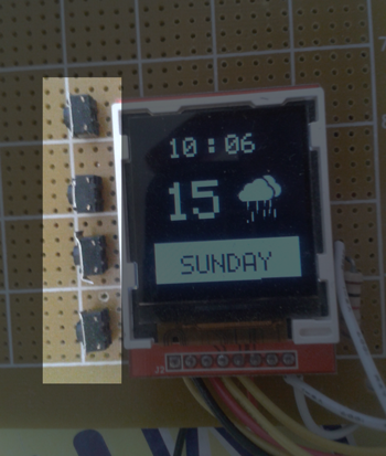
07/31/2015 at 09:29 • 0 comments1) Added 4 buttons on the side:
I soldered 4 of the buttons ( I got some vertical standing ones) on the side of the screen. These will be the main user input for the device.
It is directly connected to PA1/2/3/4 and each button has an interrupt handler.
The schematic is really easy for these: I have 3V going through each button and a capacitor for debounce handling ( I use 100nF in this case )
PS: Using the vertical buttons turned out to be bad decision (hard to solder & easy to break after long period of clicking) . Do not use them !
![]()
2) Animated weather icons :
The next big thing is the weather icons now are animated. I got this done via creating a bitmap with the different frames of the animation , later on the function on the watch loops through the bitmap array each time display a part which matches certain frame.
In this example I use 4 frames with 50*50 px for each one ( total of 50*200px)
PS: I created these in photoshop.
![]()
![]()
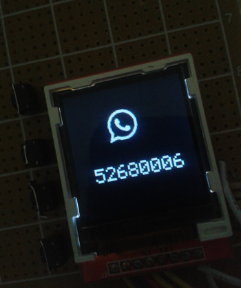
3) Notifications:
Well, an essential part of this project was displaying phone notifications such as push notifications from different apps, messages , incoming calls.
Now that is possible via a simple interrupt functions that checks what type of notification is and the content then display.
The appinventor2 does not allow for application to run in background ( to keep monitoring & updating the watch) . That's why this is not fully what I need. I guess I will have to start writing a native app soon.
![]()
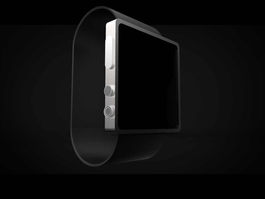
*)Bonus:
I wanted to convey what I was thinking from the start for this watch to end up like, so here is 3D model I made few days ago.
![]() Next step ?
Next step ?- On the software side :
- Working on the native app
- Adjusting the UI more and creating more attractive , more colorish UI and text.
- Adding more watch faces.
- On the hardware side :
- The challenge of creating the final small pcb is still up and I need to buy all the components.
Open Source Smart Watch
Based on the stm32f4 cortex-m4 mcu, 1.44" TFT LCD , HC-05 and Android App.
 Montassar




 Next step ?