davedarko
-
future improvements
08/25/2015 at 11:03 • 0 comments- visual indicator - I was pretty unsure if it actually worked until I checked the pictures
- optocoupler for interfacing
- use an attiny instead of a full blown arduino
- [optional] build an antenna for 433MHz to extend the range
- intervalometer http://playground.arduino.cc/Deutsch/TimelapseDe
-
lesson learned
07/27/2015 at 14:05 • 3 commentsSo when you start a new project and you don't have much time - start with the least amount of unknowns and only after it works and you still have he time, start shrinking it. Because anything will fit into a tictac / altoids box in the end! (Don't use altoid boxes for wireless stuff, btw - that should be a no brainer)
So here are the prototypes! If anyone has any cool remote designs in his mind, or movie props - I definitely want to come up with something looking more artsy fartsy. I love the zippo feeling of opening a tictac box though. And those switches that are "shielded" with a cap.
![]()
-
Woohoo it works
07/23/2015 at 16:06 • 0 commentsKind of ;) 2 arduinos, what a waste - but with that short amount of time I went for easy/known stuff. I'll update this later with a "happy - it works" face. The transmitter even worked out of the oven :D
-
works with arduino
07/23/2015 at 00:24 • 0 commentsSo I'm glad that at least the 2 Arduino setup works! Tomorrow I'll solder my 3rd and last pcb together, this time with an ATtiny85, as soon as I checked with a DIP package on a breadboard, that it actually works with one, since it's probably only maxed out. Sounds like a good idea. I might throw in a pullup for the reset line and a 100nF cap from VCC to GND as well. Should add that onto the pcb. Hm..
Off to bed now, happy hacking!
-
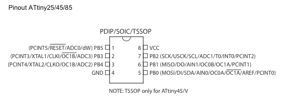
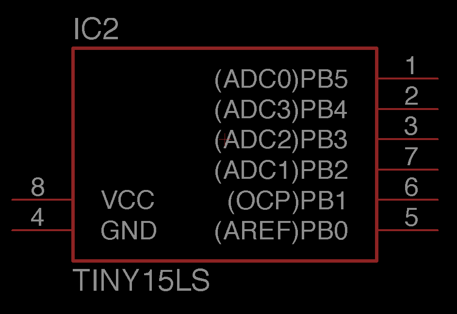
wrong pinout for the ATtiny
07/22/2015 at 23:49 • 0 commentsHere is my little "test program" to check if I'm sane or not. Turns out I am and the pins 2 and 3 are mangled up in the EAGLE library.
void setup()
{
  pinMode(0, OUTPUT); // MOSI
  pinMode(1, OUTPUT); // MISO
  pinMode(2, OUTPUT); // SCK
  pinMode(3, OUTPUT); // focus
  pinMode(4, OUTPUT); // shutter
}

void loop()
{
  for (int i=0; i<5; i++)
  {
    digitalWrite(i, HIGH);
    delay(500);
    digitalWrite(i, LOW);
    delay(500);
  }
}
Now I can reprogram the Attiny45 board again and test it another time...
![]()
![]()
-
You have to start somewhere
07/22/2015 at 22:31 • 2 commentsOn saturday I will attend the wedding party of my boss and his wife and I joked that I would totally be able to come up with something that I could take a picture with myself on the picture, without running from the first floor down to the group of guests. She said "oh well something with a raspberry pi, I guess?" - well not really, but an arduino/attiny will do.
The first idea I had was using some of the #Snail Mail Notifier pcbs, but I wasn't sure about the parts (no labels). So I figured I could totally use my AttinyX5 timelapse board which I designed to hack into a keyfob camera. I had to solder one together because I gave away the first prototyepe to @Stefan-Xp at the #Hackaday Munich: Hot Irons and Crunching Compilers - and he send me a trigger remote cable once - thanks again for that! By the way, there is a little design issue!
There is no common ground on the transistors and they are not connected to the ground pin of the board. Sounds stupid? Meh - it worked for the application I had in mind, since the tiny and the keyfob camera would have shared the battery. But not the canon camera. With a ground cable flying around that was fixed in an instant.
Next stop was finding a library that works for arduino and 433MHz - easy thing with google, here is what I found [german] http://fluuux.de/2013/12/einfuhrung-in-umgang-mit-einem-433mhz-funkmodul/ I had to download the VirtualWire from [http://www.airspayce.com/mikem/arduino/VirtualWire/] library as well. Copy, pasting and running the script gave me this:
In function 'void vw_setup(uint16_t)':
error: 'TCCR1A' was not declared in this scope
error: 'TCCR1B' was not declared in this scope
error: 'WGM12' was not declared in this scope
Turns out that the Attiny85 is covered in the VirtualWire, but not the Attiny45 (because reasons). So after a while I found out how I could fix it.
// look for __AVR_ATtiny85__ and add or replace with
#if defined (__AVR_ATtiny85__) || defined(__AVR_ATtiny45__)
#if  __AVR_ATtiny85__ || __AVR_ATtiny45__
When I finally had it compiling - felt good - it was 32byte to big - but with some restrictions to my code I got it compiling and uploading! But now I really don't know how to debug the ATtiny45, if I can't add any line of code - D'oh! Seems like I have to jump to the Attiny85, where I thought myself safe using "only" a tiny45. Maybe I should go back a little more and use arduinos first, since I got so many anyways.. ah well. Murphy get's you every time.
I wrote that with the wonderful voice of Dave Jones from the EEVblog in my head... watched him a lot again lately! Learned a lot and still had some fun with that so far!
433MHz canon remote
One of those supposed quick hacks that turns into a complete nightmare...