-
Parts!
08/06/2015 at 00:38 • 0 comments![]()
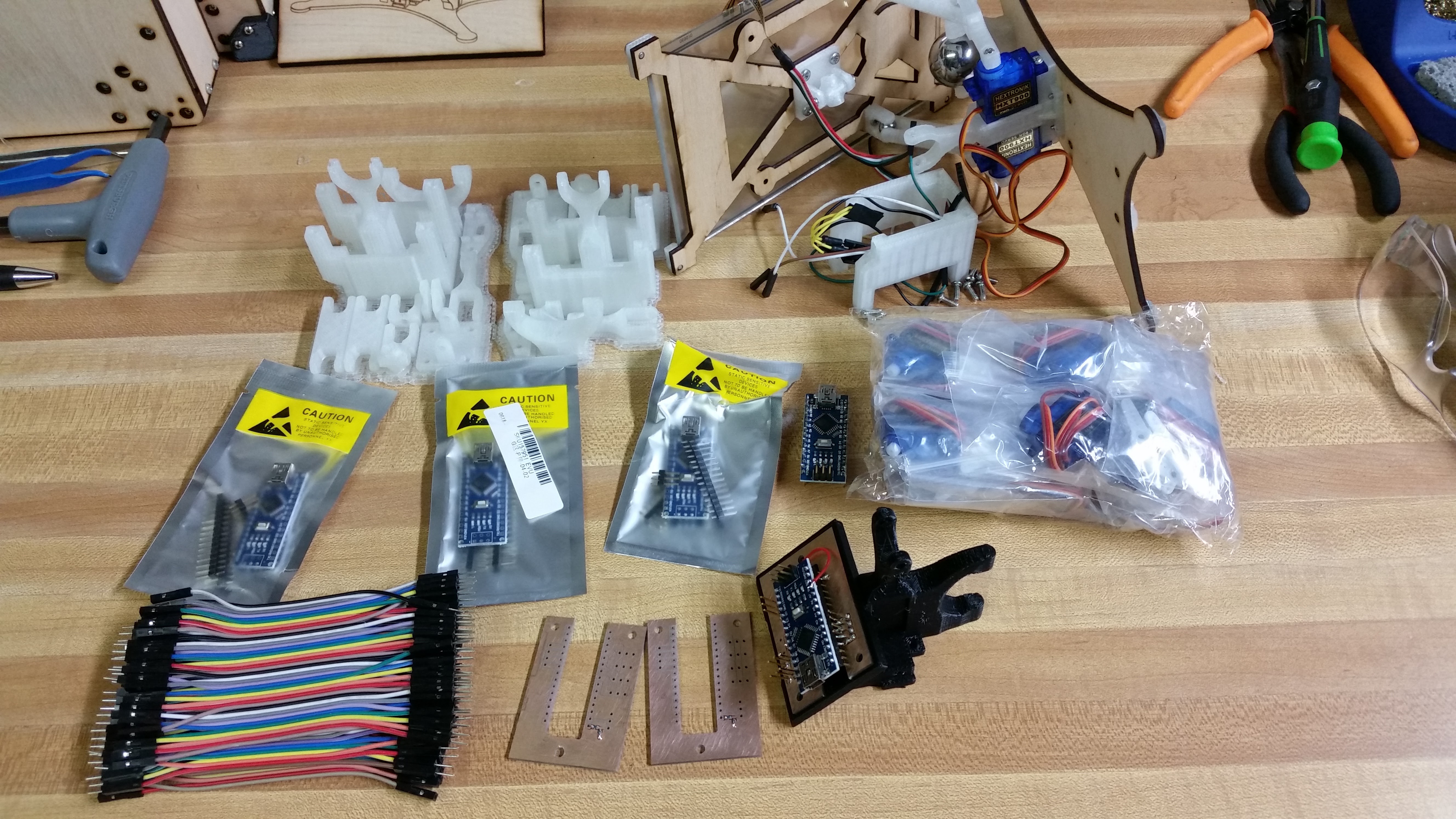
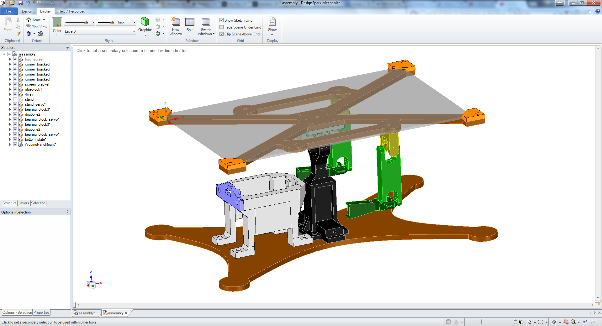
The parts that I got on order last Friday have started showing up. I'm still waiting on the PCBs, but I'm not expecting them until early next week. Yesterday at lunch I used the PCB mill at work to cut out 4 copies of the interface PCB. That way I can test it out, and if my boards from OSHpark don't show up in time I have them as a backup. I've also been working on redesigning the center 3D printed piece of SAB3T to incorporate the board mount and the 1" ball bearing holder. The main reason that the board mount was separate was so that I could stuff all the wires underneath. There are a lot less wires now with the PCB, so it was sub-optimal to keep the same setup. As I type this I have what I think will be the final version of that mount printing.
It looks like this weekend is shaping up to be a busy one, so hopefully I can keep to my schedule!
-
Board Layout
08/02/2015 at 20:40 • 0 commentsI'm going to have to adjust my schedule. :)
I was going through my project wiring to start making a wiring diagram. The way that I wired my prototype is with a bunch of jumper wires. I have been planning on this being a DIY kit that the user assembles. So I was going to include a bunch a jumper wires and diagram and the use would go to town wiring it up.
But the more I thought about it, the less I like that solution. It isn't elegant and requires some wire striping and soldering. In the back of my mind I had been kicking around the idea of making a PCB, but didn't have it in my schedule and thought that jumper wiring would be fine.
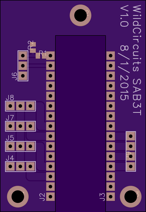
So the PCB for SAB3T is a 2 stage approach. Stage 1 is basically breakout boardfor an Arduino nano. Here it is:
![]()
This board has 3 pin headers for the servos to plug into, a 4 pin header for the touch screen connection, and a 3.3v compatible serial header. That is all the stuff that was wired with jumpers. I put the board order in with OSHpark last night, but it is highly likely that I won't be getting the boards in before my ship date. I have access to a PCB router at work, so I'll be running off a few boards at lunch break this week. If my OSHpark boards don't arrive in time I'll build my 3 demo units with the boards from the PCB router.
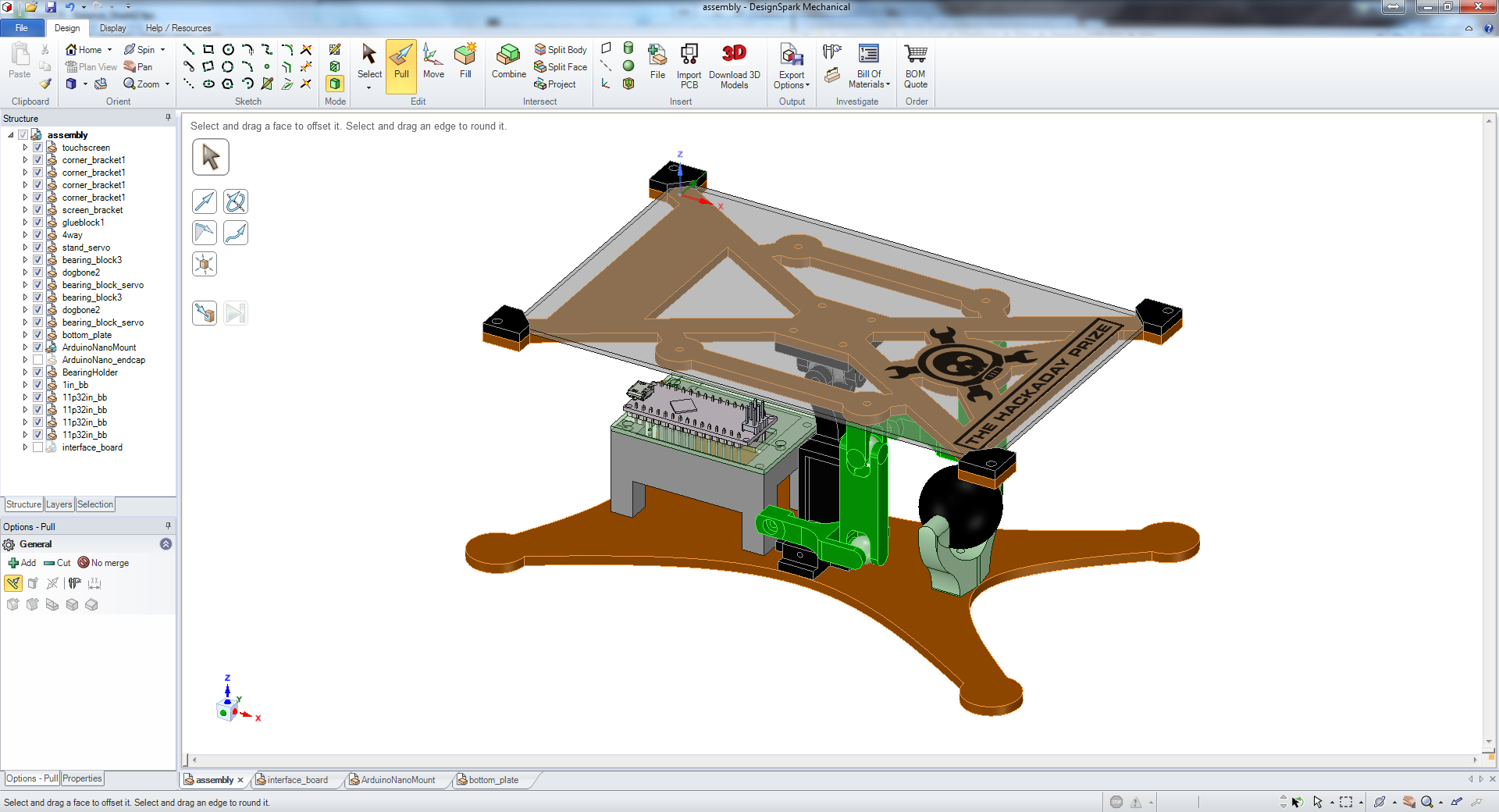
This make the wiring significantly easier and more robust. Here is what it will look all assembled:
![]()
Stage 2 will be a custom Arduino with the proper connections broken out and a couple of mounting holes. I won't be looking into that until after the Best Product competition is done.
-
Project Schedule
08/01/2015 at 21:01 • 0 commentsSince this is an entry for the "Best Product" category of the 2015 Hackaday Prize, there are a few extra requirements that I need to meet. The most challenging is that I need to ship 3 prototypes to arrive at the Hackaday offices by 8/17.
I'll admit I was a little late to the game when I decided to enter SAB3T in the competition. I was stuck on trying to create something world changing, which is hard to do. SAB3T isn't going to eliminate world hunger or cure cancer, but it can be a piece of puzzle when it comes to improving the available resources for STEM education.
So I officially kicked off my entry on 7/24. At that point 8/17 was less than a month away so I started off by making a project schedule to make sure that I could deliver and meet all the requirements. My schedule looks like this:
Monday, 8/17 - SAB3Ts at Hackaday offices
- 5 days worst case shipping -
Tuesday, 8/11 - SAB3Ts are shipped
- 1 day -
Monday, 8/10 - SAB3Ts are packaged and prepared for shipping
- 3 days -
Friday, 8/7 - SAB3Ts are assembled and tested over the weekend
- 7 days worst case shipping -
Friday, 7/31 - All required parts for 3 kits are ordered
So I stuck to my schedule and managed to get all the parts ordered last night. I already had the wood and plastic in stock. Over the next couple of days I'll be getting all the laser cut and printed parts fabricated to prepare for next weekend's build. I'll also be acquiring my shipping materials (boxes, padding) this week. This schedule has a little bit of padding built into it. For instance, it should only take 3 days max for USPS to get my package to Hackaday, but I've scheduled for 5. My day job has been very busy lately, so an external factor like my job could impact my schedule.
Once the proto units are shipped on 8/11, I'll use the remaining time make the 2 required videos and ensure I have all the required project logs. I think at this rate I'll be all set on project logs.
One little side note: if I had started this entry about a month earlier and stayed on top of the schedule I would have ordered the touch screens for my judging units from an overseas vendor and paid 1/3 the price I paid to source them in the US. But I would need to have 4 weeks in my schedule to comfortably do that.
-
More Improvements: Proto 3 and Proto 4
07/29/2015 at 02:06 • 0 comments![]()
For Proto 3 I changed the things that I mentioned in the end of the Proto 2 post.
- I designed fully printable servo horns so glueing is no longer necessary
- The Arduino holder was optimized to print without support material.
- Everything that screws to the bottom plate now screws in from the bottom. This is much easier to assemble / maintain.
Proto 3 is the version that I took to my lunch time talk that I spoke about in the previous update.
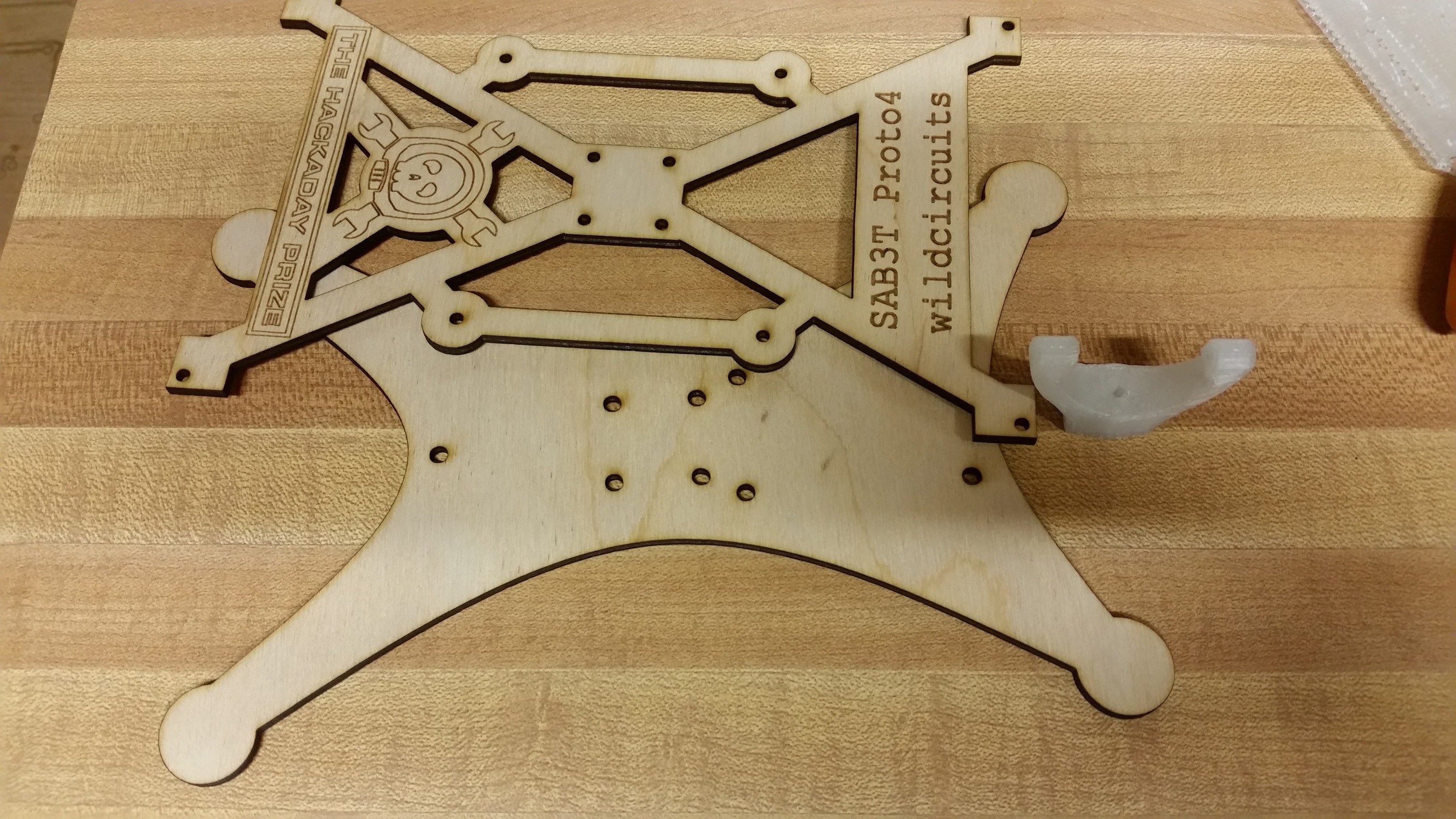
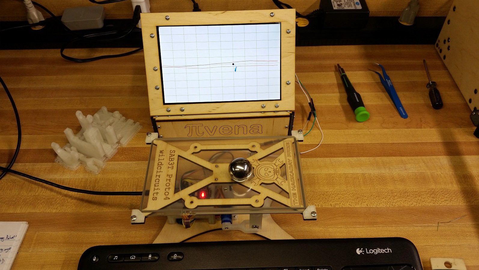
Proto 4 is really kind of cosmetic I'm pretty happy with everything now, so this might be the rev that I produce for the Best Product judging. I added the Hackaday Prize logo as well as a name plate to the wood piece securing the touchscreen. Since the touchscreen is clear you can see that stuff very clearly.
I also added a storage holder for the 1" ball bearing that rolls around the touchscreen. It screws to the bottom plate.
![]()
![]()
I shot a video of it all operational. One of the things that I haven't mentioned yet is the live graphing python script that I wrote to show what is going on in the PID loop that is running in the arduino. The python script has been tested and working a raspberry PI and a windows 7 laptop. It will probably run fine on Mac too. I'll do a post soon going into the script in detail.
If you follow my other projects, you'll recognize that I'm using my PIvena Raspberry PI case to display my live graph. That is the new 1280x800 LCD version that I'm running it on.
-
SAB3T: Lunch Time Talk
07/29/2015 at 01:15 • 0 commentsWhen I'm not doing fun projects on Hackaday.io, I work as an RF Engineer for a large communications company. My role transitions between R&D and new product development as is needed, but I work with the same core group of engineers and they've come to know the types of things I make in my free time. When I competed in the 2013 Sparkfun AVC (and took 3rd place in the PBR class!) I held monthly lunch time talks where I would reserve a conference room and invite all the other engineers I work with. Lunch time talks were great because I had lots of people interested in hearing about my rover development but not enough time to tell people individually. After the AVC was done I wanted to keep up with my lunchtime talks. So once every 2 or 3 months I’ll bring in a project that I’m working on and use it as an opportunity to introduce some tech that I’m playing with that they may not be familiar with. I usually spend about half the time showing off what I’ve made and the other half giving a crash course on what I had to learn to do it. I’ve talked about RC servos, ultrasonic distance sensing, quadcopters, SLAM (simultaneous location and mapping), my laser cutter, 3D printing, Google cardboard, a hobby radio I made, raspberry pi, and most recently SAB3T.
I started off with a crash course on PID loops then demonstrated the operation of SAB3T with different loop parameters. I made a live graphing python script that I put on the conference room projector. That really helps in understanding what is going on.
It turns out that one of my coworkers had previously worked at a company developing inkjet printers and had a lot more experience and knowledge on PID loops than I. He clarified a few things and shared some interesting war stories about tuning inkjet printers. Everyone else was familiar with the term, but wasn’t familiar enough to remember what the acronym stands for. Regardless of how well you understand what is going on behind the scenes, it is fascinating to watch SAB3T at work. Balancing the ball bearing on the touch screen and moving it between several preprogrammed positions is mesmerizing.
After my talk I kept SAB3T on my desk for a few weeks. As people walk by they push the bearing and see how SAB3T reacts, and the bearing is rarely dropped. I also met several random people who stopped to talk, wondering what this thing was on my desk. The president of the company even stopped by to see it!
One of the key takeaways I have from that lunch time talk is that even in a room filled with professional engineers, PID loops are barely understood. But it’s not just PIDs, there is a need for entertaining teach aids that can be easily acquired by anyone. The best learning is when it is a byproduct of doing something interesting. For me I hope SAB3T is the first of many educational kits that I can bring to market.
-
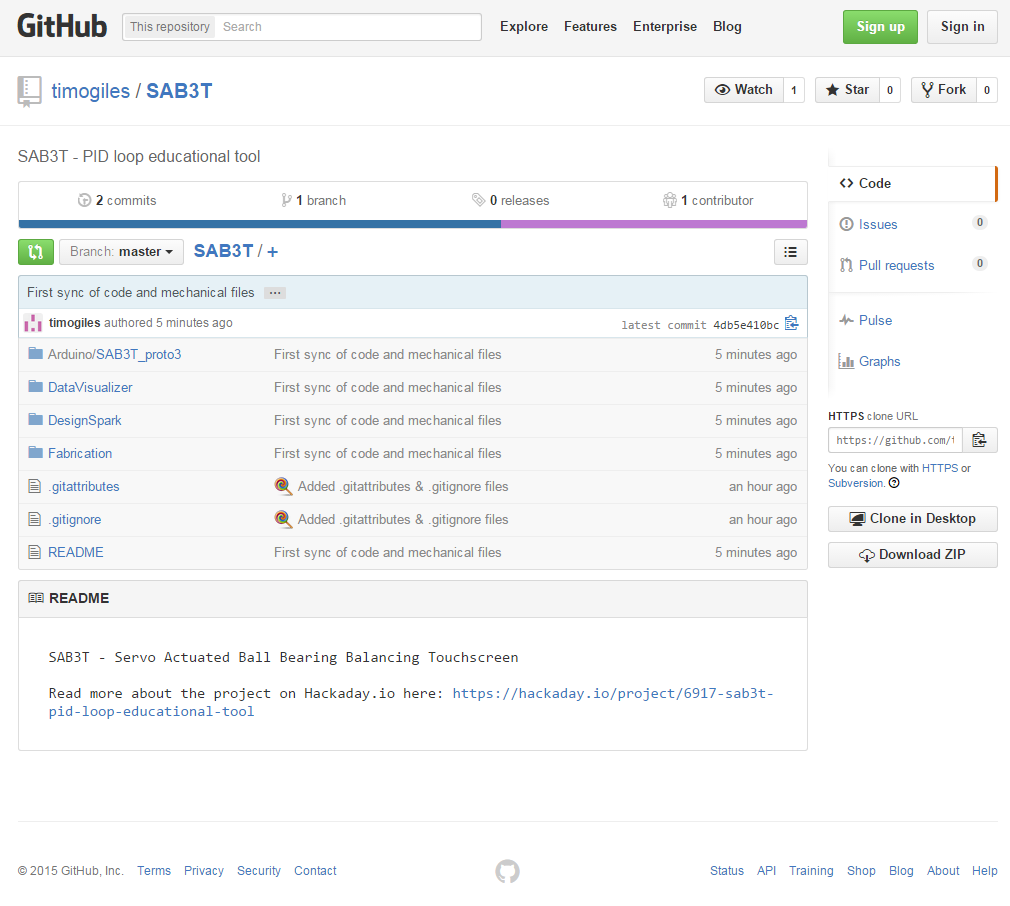
Files are up on GitHub
07/26/2015 at 23:18 • 0 comments![]()
I'm no wiz at github, but my design files for fabrication and code are now up. There is a github link on the side bar or you can just click here: https://github.com/timogiles/SAB3T
Word of warning: The code isn't fully commented yet, but it works. I'm going to clean it up as I go along.
-
Redesign
07/26/2015 at 22:21 • 0 commentsSAB3T - Prototype 2
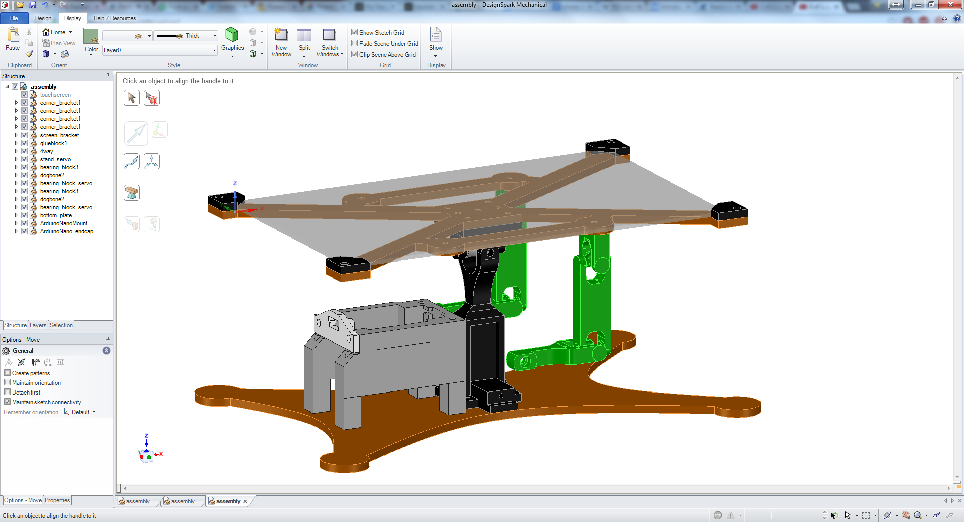
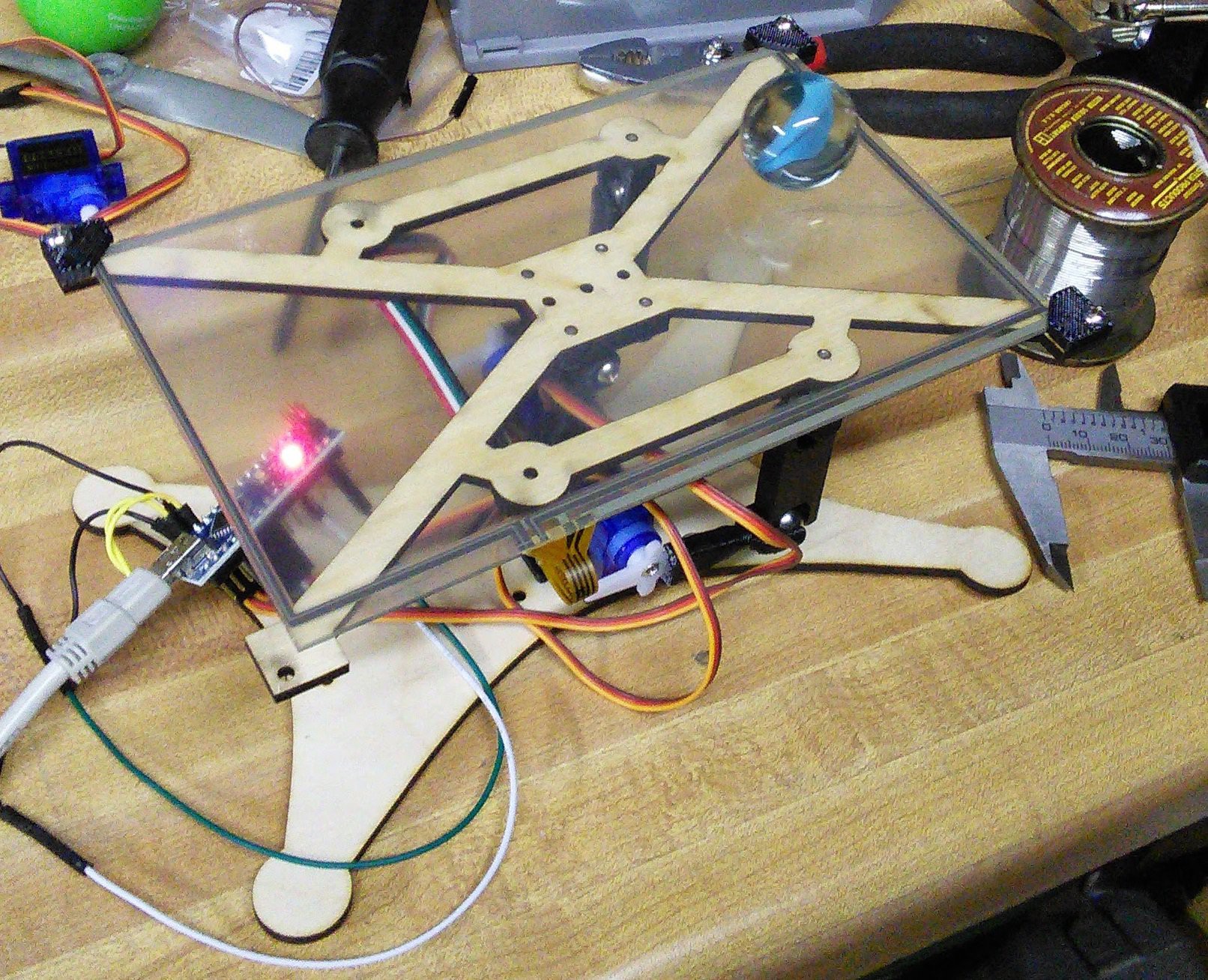
I mentioned in the last update that my initial design worked but was to big and had stiffness issues. I was able to solve both problems by moving the servos and Arduino to a new location underneath the screen. There is now a central 3D printed part that holds the servos and a universal joint. I changed to an Arduino Nano to reduce size. There is a wood plate at the bottom to act as feet and a wood plate on top to hold the touchscreen. My touchscreen measurements were correct this time so my printed brackets now work.
![]()
![]()
This version worked quite well, but there were still several things that I wanted to improve:
- The servos need to have a part glued to the servo horn. This needs to be replaced by a fully printed part.
- The Arduino holder needed support material to print. Ideally I want this to print without support material.
- The Arduino holder and the central tower were designed to be screwed to the wood from the top down. Once the screen is installed you cannot easy unscrew them without removing the screen.
SAB3T prototype 2 in action:
-
Humble Beginnings
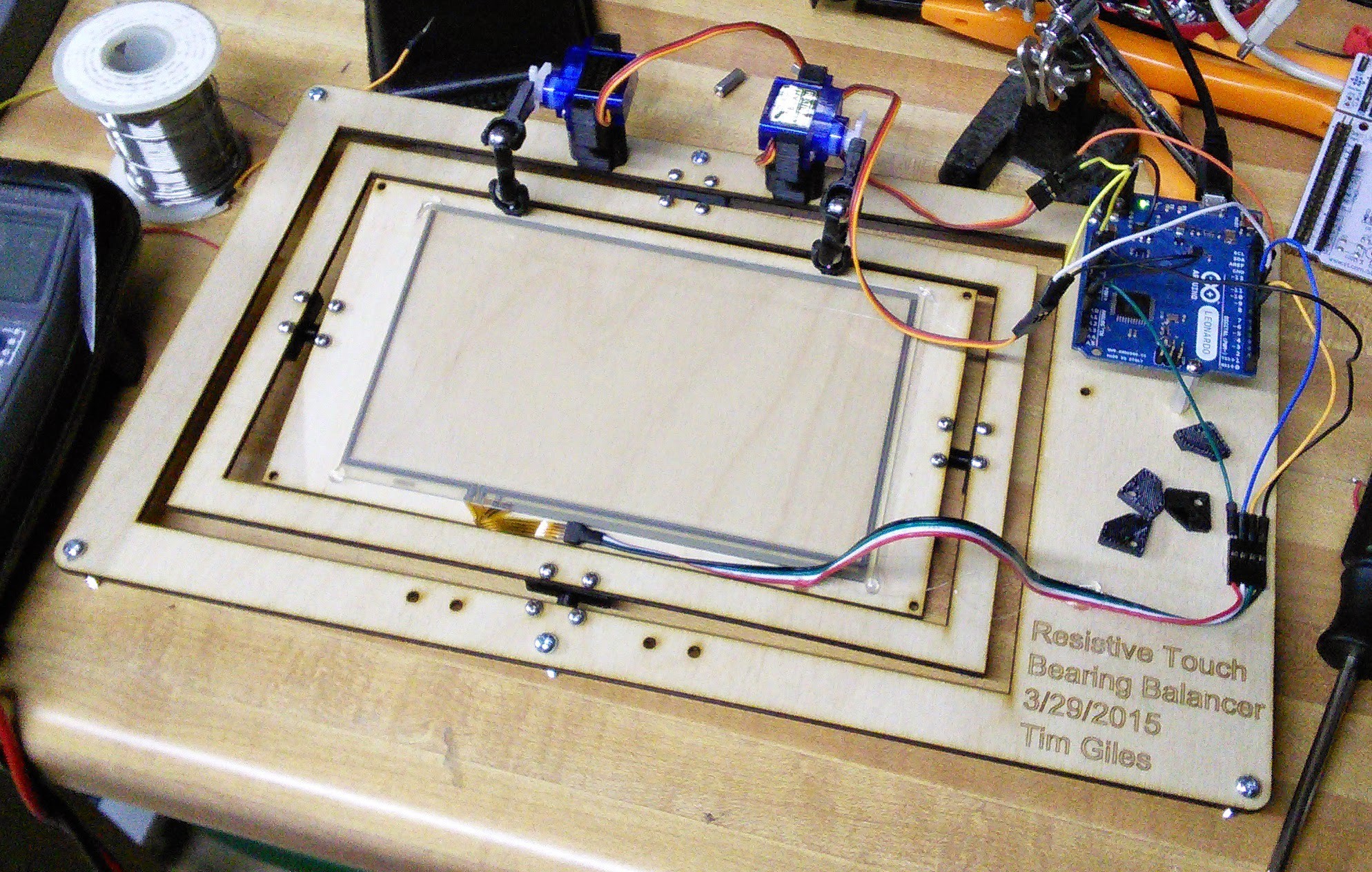
07/24/2015 at 20:59 • 0 commentsI started working on SAB3T in March of 2015. It took me about 2 weeks of evenings to get to this point:
![]()
![]()
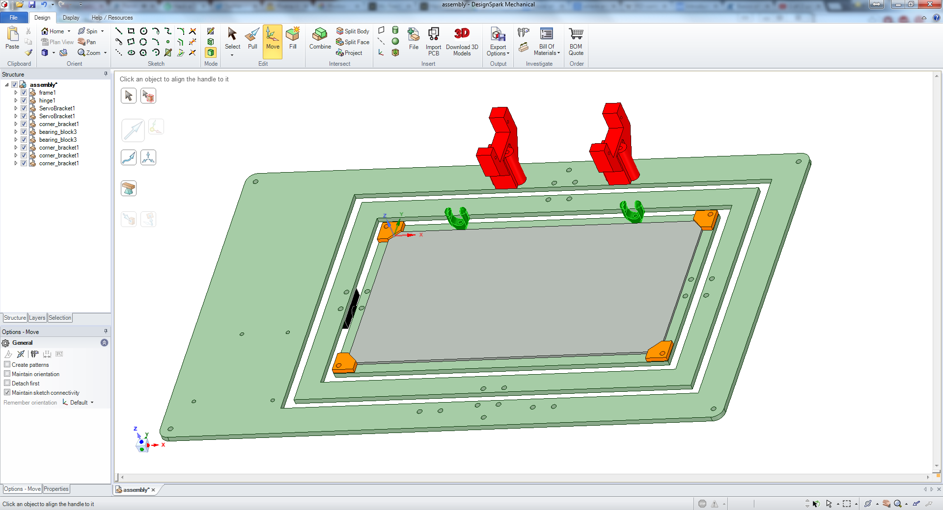
There were a number of problems with this design but it accomplished what wanted to create. Mechanically it wasn't stiff enough. I used 1/8" baltic birch plywood for the frame becuase I had a spare sheet of it, but with how long and narrow the outer and inner frames are it would flex if the servos moved to fast. I'm using 2" long screws as standoffs to hold the whole thing up. Unfortunately that isn't quite tall enough and if the servos move the screen to too great an angle it hits my workbench. I also goofed up my touch screen measurement. I accidentally wrote down the measurement as 1" wider than it actually was, so I had to hot glue the touchscreen down instead of using the brackets that I printed. Last problem? The whole thing is to big! I wanted to have this on my desk at work, but it took up too much space. Time for a revision....
SAB3T - PID Loop Educational Tool
Learn how to use PID loops for fun: SAB3T - Servo Actuated Ball Bearing Balancing Touchscreen.
 Tim
Tim