 charliex
-
Build Plate
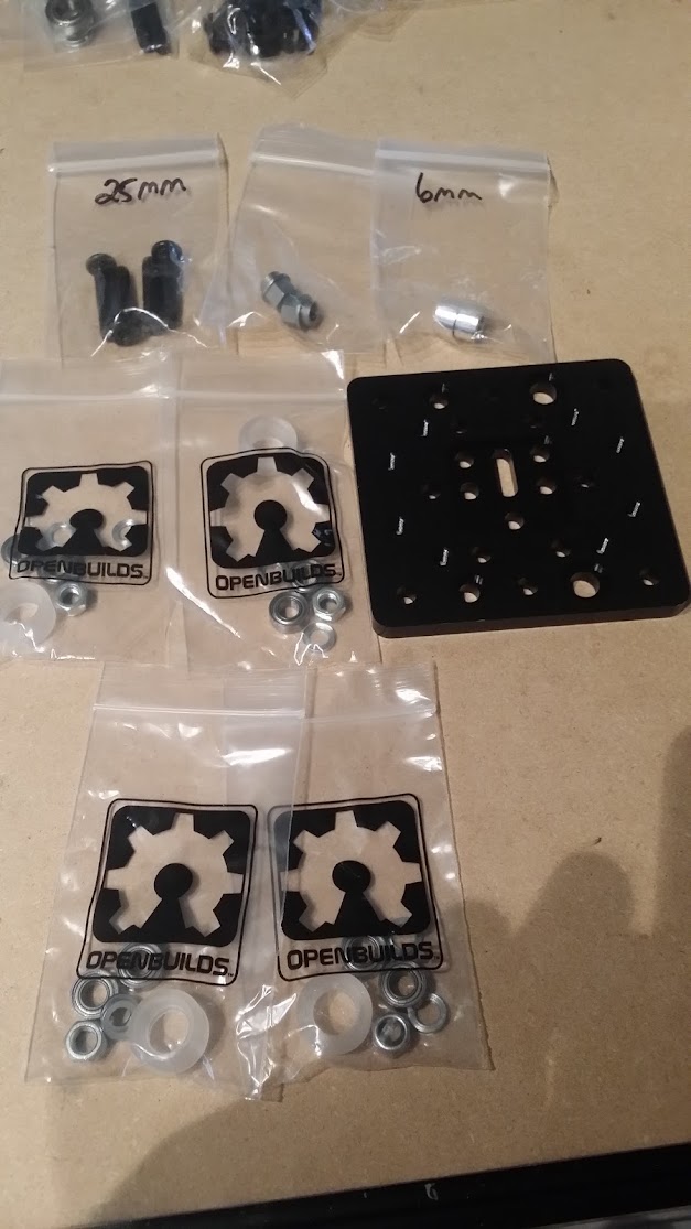
07/27/2015 at 00:37 • 0 commentsFor the build plate, it is going to be
- 1 X Build Plate
- 4 X Wheel kits
- 4 X M5 25 mm bolts
- 2 X 6 mm spacers
- 2 X 6 mm eccentric
- 1 X 8 mm anti backlash lead screw nut block, the non anti lock is not included
- 2 X M5 nuts
- 2 X 3 mm spacers
- 2 X M5 x 20 mm screws
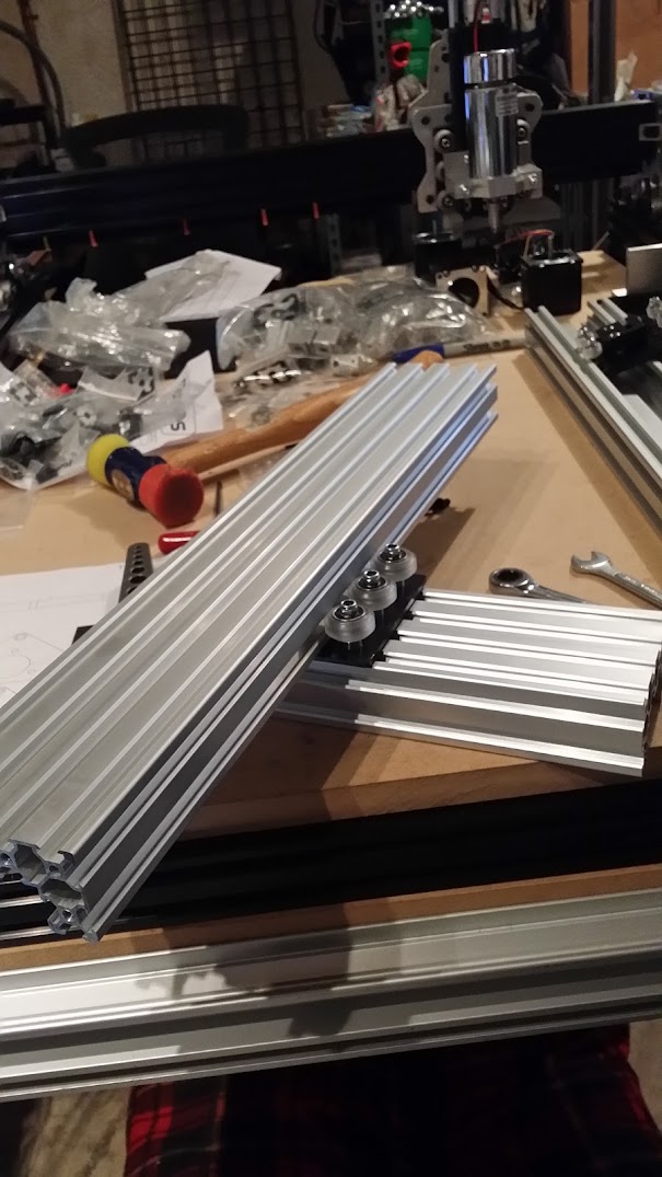
- 1 X 500 mm C beam
Clean the 500 mm C beam of swarf, check for issues where the wheels will track.
Take the build plate and drill out the 8 out-most holes to 6 mm so that the self tapping screws will just pass thru, this is where the MDF or such mounts and rather than do it later when the wheels and nut runner is installed, so less chance of getting swarf into them. Countersink the holes a little, just to knock out the edges.
Build the wheel kits
Same as before
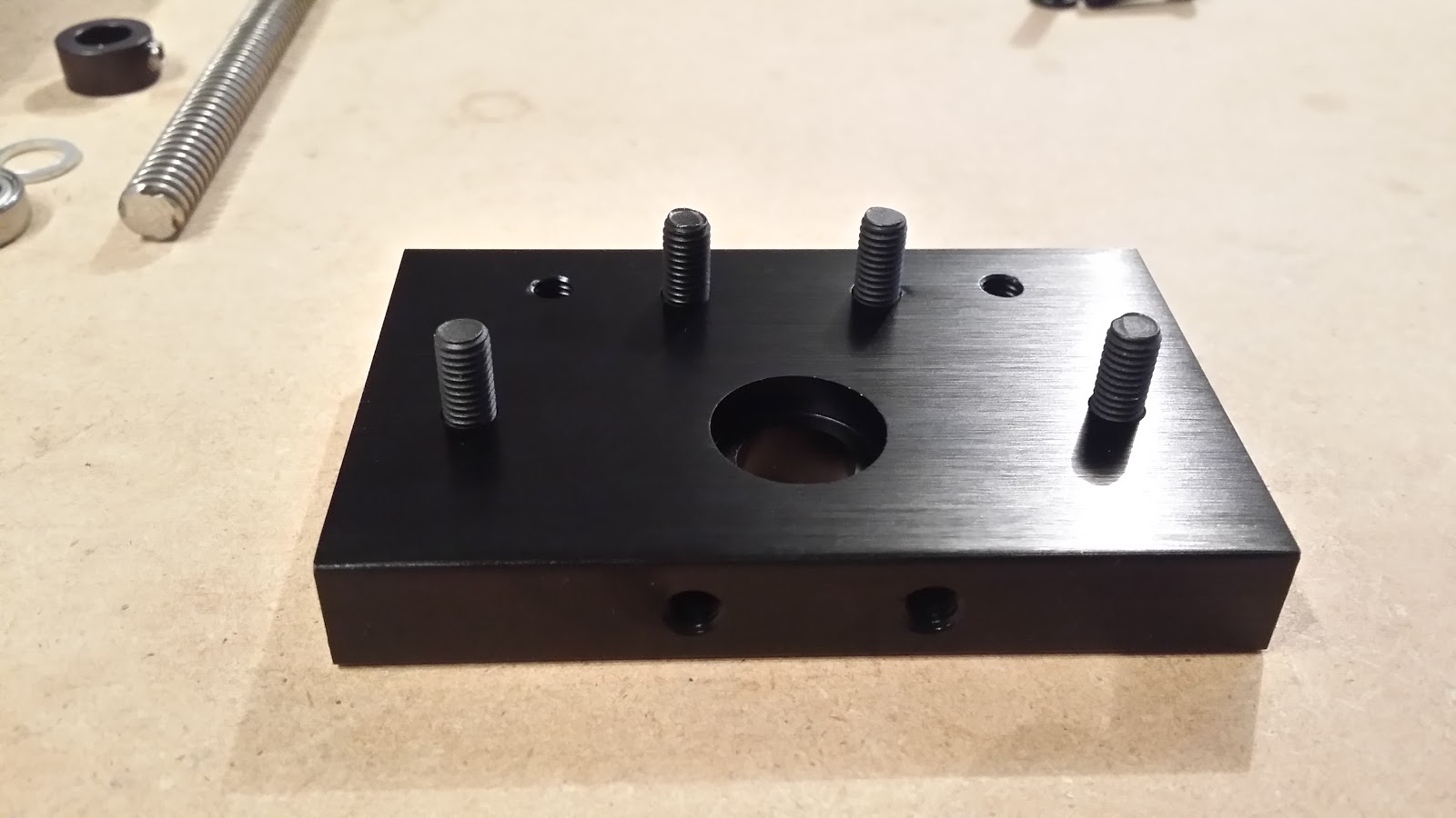
Take note of orientation of the build plate, install two with eccentrics, two with 6 mm spacers. 25 mm bolts
Both on with 6 mm spacers
Eccentric side 2 mm bolts
Install the wheel kits, 1 mm spacer on top of the 6 mm spacer, and samee on the eccentrics spacers, add wheels then the nut and tighten
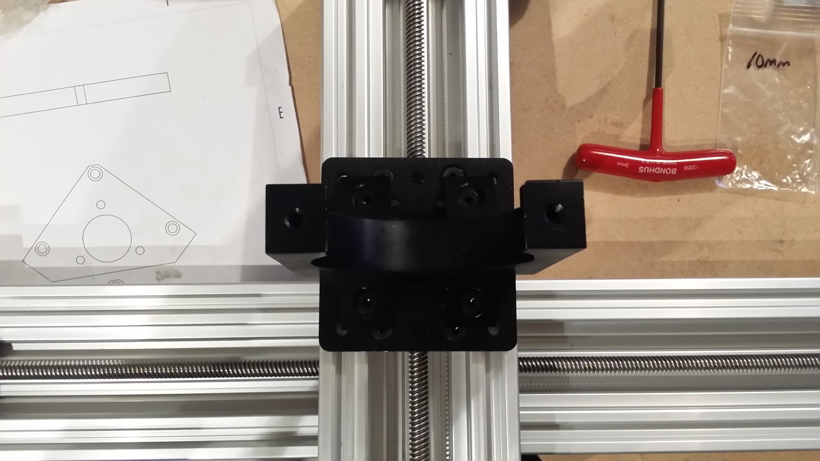
Anti-back lash nut, I've already installed the set screw and holding nut here.
Install the bolts for the nut screw so the lead screw would be centered
Add the nuts to the holders.
Clean out the nut again, this one was the worst of the bunch so far, I could barely thread it the start, and also had to treat the threads on the lead screw where they've been cut, small file again to clean up the edges. Ended up with the cordless drill slowly moving the lead screw back and forward after about 10 cycles by hand first.
This is the result
Next add the gantry plate to the last 500 mm C Beam, adjust the eccentrics as before, so nice and tight and no slop.
Next step is prepping the MDF for mounting and waste board. Then building the frame out.
-
Spindle mount and various
07/26/2015 at 22:30 • 0 commentsWe need
- 1 X Spindle Mount, i'm using the dewalt 611, people keep using the bosch but read up about it at precisebits.com
- 4 X right angle brackets with nubs
- 4 X black right angle without nubs
- 12 X M5 10mm bolts
- 2 X M5 20 mm bolts
add these here, i'll have to see where these are attaching to, they're meant to go in channel so they have little nubs to help align, if they're not rotated in channel, i usually remove them but lets see what happens.
so add the 90 corner brackets with the 10 mm M5's to the underside of the gantry to the 4 T-Nuts, one of my T-Nuts had damaged threads, so note to self check before installing that they thread OK, often its a pain to get back to them.
same other side
add the router mount, 4 black right angle brackets, not these do have the nubs like the others which is good.
they go on the inner holes of the 4 available.
squared off
mount on the z gantry. 4 more 10 mm M5's, square it here as well, though we can adjust later.
always hard to photograph.
add the front part of the router mount, 2 X 20 mm M5 bolts
and put in place, mine didn't thread all the way, since no spindle in place
And another stage done...
ext it's the build plate, I'm going to take a break for some coffee.
-
X Axis actuator
07/26/2015 at 21:58 • 0 commentsOn to the X axis, similar to the one we just did, just longer C Beam and lead screw etc.
- 2 X 40 mm aluminium spacers
- 1 X 1/4"? x 8 mm flexible coupler
- 2 X 8x16x5 bearing (688Z)
- 2 X 8mm shim
- 8 X T-Nuts
- 2 X 8 mm lock collar
- 8 X M5 20 mm bolts
- 2 X C Beam end plates
- 2 X M5 55 mm bolts
- 1 X Nema 23 stepper motor
- 1 X 8 mm lead screw 500 mm
- 1 X 500 mm C beam
Arrange in order
i added the leftmost (looking from the front of the machine (c side ) plate with the 4 20 mm M5's
add two of the T-Nuts on top side going up to the plate., they won't slide in after the Z gantry is added, the wheels block them.
add the Z gantry
add the lead screw, again knocking them down with sandpaper first so the bearings slip fit. On some of the lead screws the threads at the end are damaged so either use a die or a small file to take off the damaged ends of the thread so it can thread into the delrin nut lock
Add the bearing
add the lock ring, 8mm washer . round side towards bearing, flat side to bearing again. flush the lead screw to the end of the plate.
add more T-nuts, four on the back bottom slot, looking at the underside of the X C beam C channel is looking up, lower slots.
and then top side, add two more, so this is looking down at the C beam, C channel forwards.
add the lock rink, spacer again round side to bearing, and bearing
add the plate with the 4 20mm M5's
leave a small gap, preload the bearing into the hole and lock it down with the locking collar, careful how hard to tighten the set screw,
now tighten down the 4 20mm M5's on the plate, which squishes it all together and preloads the bearing.
Add the coupler, making sure it doesn't run on the plate.
add the 55 mm bolts to the Nema 23 motor.
add the 40 mm standoffs
screw them into place, and tighten the set screw on the coupler
Check for slop, and adjust as necessary, make sure the lead screw can turn and not too much preload on the bearings.
Another step complete
-
Z Axis
07/26/2015 at 20:52 • 0 commentsFor this part, we need
- 2 X 40 mm aluminium spacers
- 1 X 1/4"? x 8 mm flexible coupling
- 2 X 8x16x5 bearings 688Z
- 2 X 8 mm shim, look like thin washers
- 2 x 8 mm lock collar + set screws
- 8 x M5 20 mm bolts
- 2 X C Beam end mount plates
- 2 X M5 55 mm bolts
- 1 X Nema 23 stepper motor
- 1 X 8 mm lead screw 250 mm length
And Bad Boys II playing in the background
Arranged out in order of build
Four of the 20 mm M5's into the bottom block (they're the same)
Bearing fits here
The lead screw needs to be knocked down for about 40 mm in, so with 220 git sandpaper and a cordless drill, finished with 1500, make sure to clean very carefully you don't want grit in the lead screws or bearings afterwards, clean them elsewhere and don't over tighten the chuck on the lead screw, take your time and test often til the bearing is a slip fit.
took me about 40 seconds each side. You do not want the bearing to have side to side movement, it should be snug but smooth on and off.
lower block goes on, four bolts, bottom of the Z is where the gantry plate is.
Always so much swarf in these things so blow them out with air. note orientation of the eccentrics on the plate. make sure its all riding properly and adjust the eccentrics etc here.
Insert lead screw
Lower bearing
Add washer (rounded side towards bearing, flat side towards lock collar) and lock collar.
Flush the bottom of the lead screw to the bottom of the plate
Gently tighten the set screw on the lock collar, don't over do it or it'll strip. Try to think about having the various set screws all face the same way so it is easier to work on later.
Top side next, same as the bottom, lock collar, washer round side towards bearing, bearing and plate. four 20 mm M5's
Adjust so there is no slop in the Z gantry, either by tightly holding up the collar, or by backing off the four M5's holding the plate, and then applying some pressure to the collar up so that it preloads, tighten down the M5's don't over do it, just enough so its not able to move up and down without turning the lead screw
add the coupler, asks for a .5 mm gap , but my lead screw wouldn't get closer than this. Doesn't matter as long as it is not riding on the surface of the plate
Put the 50 mm bolts into the NEMA 23 , have the wires coming out between the bolts.
add the standoffs, and thread into the plate, note the wires are facing towards the back of the gantry.
tighten the coupler to the motor shaft.
And we're done Move it around and test it etc, no slop and not too hard to move, make sure the lead screw doesn't bind.
-
Adding Z C beam to X gantry
07/26/2015 at 19:30 • 0 commentsPut together the X + Z gantry.
- 8 X T-Nuts
- 8 X M5 x 10mm bolts, i used the pancake heads
- 8 X Slot Washers ( washers !)
- 1 X 250 mm C Beam
Plate onto the 250 mm C Beam
Add the 10 mm M5's, some of them go into the large holes
I added tape over the heads to hold the bolts in place.
Now add the washers.
loosely add the t-nuts, just enough to hold them in place and align them like this
Insert into 250 mm C Beam
I squared mine off with a mini machinist square
And tighten down the M5 bolts, i did a couple snug then tap gently with a soft non marring hammer, and checked it for squareness as a i tightened it down.
Add it to the 500 mm C Beam
Adjust the eccentrics so they are nice and tight, so you have trouble turning the wheel by hand, check squareness and movement so there is no slop, make sure all the wheel nuts are tight
-
Next Gantry
07/25/2015 at 20:15 • 0 commentsOn to the next part, we need
- 6 X Wheel kits
- 6 X M5 x 25mm screws
- 3 X 6mm spacers
- 3 X 6mm eccentrics
- 1 X gantry plate
First put all the wheel kits together.
put the bearing in first
add the 1mm spacer
add the next bearing
repeat 6 times, and then i rebagged with the nut and other 1 mm spacer for now.
Three of the 25 mm bolts on to one side of the gantry, the smaller holes first. the plate seems reversible
add the 6mm spacers
next the 1mm spacer
add wheel and nut, finger tight
repeat for the other two wheels and nuts
three more bolts in the larger holes, this is where the eccentrics go
add the eccentrics, make sure the go in the hole like the one on the left.
add the 1mm spacer
add the wheel and nut, finger tight
repeat for the other two, i aligned the eccentrics to point out to the edge.
i snugged the nuts so that i can move the eccentrics later, on the three bolts with the 6mm spacers, they can be tightened now.
Now the Anti Backlash lead screw nut block again, again same thing as before the non anti backlash version wasn't included.
- 1 X 8mm anti backlash lead screw nut
- 2 X M5 nuts
- 2 X 3mm spacers
- 2 X M5 20mm screws
put together the lead screw nut
add the nut to the set screw
add the two 20mm bolts here
add 3 mm spacers
put the nut block with the two m5 nuts
and tighten, don't over do it since its plastic
clean out the swarf again
now mount onto a c beam and adjust the eccentrics, some damage on the c beam but it doesn't matter since its not on a contacting surface
i used a small 10 spanner
let it slide down by itself this time, so not too tight, since it'll be adjusted later.
-
Putting it together
07/25/2015 at 18:44 • 0 commentsLaying out the parts and checking its all there, the gantry is the Z bag. There was no non anti backlash nut in my packaging, so can only install the anti backlash one.
X
Z/Gantry
I assembled the wheels, bearing inserted, spacer, bearing. then rebagged them.
The rest of the parts to mount the wheels
There are two sets of holes, two larger for the bolts + eccentrics, two for the 6mm spacers.
Bolt , smaller hole, 6mm spacer, 1mm spacer. wheel, nut
both spaced wheels on, showing the orientation of the eccentrics.
1mm spacer again
all on, just snugged
The way i do the eccentrics, is that if they just fall in to the C beam, then they're too loose, so they'll just sit on top like this, rotate the eccentrics til the gantry has no slop. Make sure to look for swarf first.
it should sit wherever you put it, when the c beam is sitting vertically.
So all the parts from that subset of the Z bag should be used up, the 25mm bolts and 4 wheel kits, one c beam and the gantry.
Next it is :-
- 1 - 8mm Anti-Backlash Lead Screw Nut Block + set screw + nut , there is no lead screw nut block in my kit. It is a different set of holes
- 2 - M5 Nuts
- 2 - 3mm Aluminium Spacers
- 2 - M5 x 20mm Screws
I setup my nut block like this
It should be installed like this, the provided drawing is incorrect, it shows the nut on the set screw going towards the other side. The set screw isn't going to be that easy to change later.
Before screwing it down, clean out with the lead screw i can see the swarf in mine just eyeballing it, run the screw through it a few times taking care to remove the swarf as you go. The ends of the lead screws are cut so the thread is damaged there and can mar or cut the plastic, so you way want to smooth off the end of the thread a little before doing this step, make sure it threads smoothly. About a dozen back and forth and this is what came out.
add the 3mm spacers
That's it for this step.
-
Unboxing
07/25/2015 at 03:04 • 0 commentsGot home and the box was here
CNC unboxing pics.
some damage before it was packed up and shipped, very minor surface dings, otherwise nice.
OpenBuilds C-Beam™ Machine Build
C-Beam Machine is a CNC machine design based on the popular V-Slot linear guide system.


 add 3 mm spacers


 all on, just snugged


