Martijn
-
Easy inspecting with a stickvise
05/21/2018 at 22:08 • 0 commentsI was trying to repair my AVR Dragon
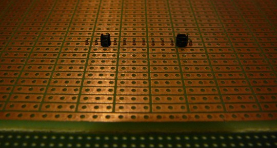
I think my reset line is fried, and the given solution for this seems to be replacing two IC's. Sadly 2 pads came off along with one of the IC's and I tried to fix it with some tiny wires. But the parts on the dragon are rather small and i was afraid I might short some pads, so I looked for a way to do some inspecting.
My magnifying lamp isn't ideal for that, but I'd just received the magnifier I bought from a chinese webstore (tbh, I didn't buy it with electronics in mind). And this was just too easy to do:
If I had known I was going to do this, I might have looked a bit better at the optimal magnification and focal lengths and such.
The dragon didn't make it (yet), my last replacement IC sprung from my tweezers and disappeared in a puff of smoke. (I have an Atmel ICE now, which is nice and fast, but has a stupid 1.27 mm grid connector)
-
Stickvise Hack (upgrade)
01/29/2018 at 23:29 • 1 commentMy plan for today was to finally repair the power switch on my drill press.
I noticed a discussion on @Alex Rich 's Gooseneck for the stickvise project, and got an idea and a boost to really finish the repair today. More on the drill later, but here's what I envisioned when I saw the Gooseneck project today.
This might have been my fastest idea-to-video ever.
-
Some thoughts about my version of the Stickvise
09/17/2015 at 23:59 • 4 commentsI was hoping to be able to post this sooner, but I was busy (preparing for and going to a festival and a vacation and other stuff).
I made a Stickvise video for my Youtube channel. It has two parts, a bit of construction and a time-lapse video of me using it for the first time while soldering a pcb kit.
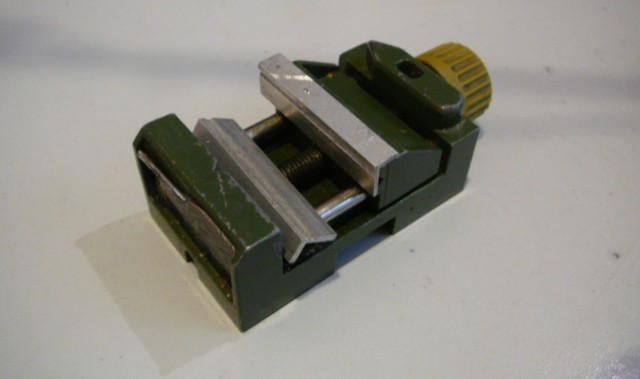
I have a small Proxxon vise with two slotted aluminium strips, but that vise can only hold narrow pcb's (3 or 4cm? ). For larger prints I used to use a +/- 15 cm x 30 cm piece of wood wrapped with 1mm thick aluminium sheet to protect my desk.
![]()
Working with the vise for the first time was awesome. The moment a board is clamped in a the Stickvise it becomes one with it, and handles like solid object with some mass instead of a flimsy board. No user manual or explanation is needed, there is just soldering before and after a Stickvise.
But after a while I started wondering if I was using the vise as I was 'supposed' to. I noticed I was using the vise on its side a lot. I think it had to do with the kit I was soldering. The leads on the provided resistors were a bit thin compared to the hole sizes. And the board had an high voltage part which needed to be tidy, so I didn't want to bend the leads outward to much to hold the components for upside-down soldering.
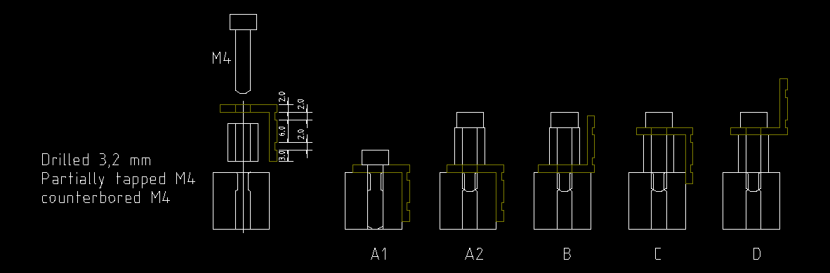
I hadn't considered it, but with the jaws raised (position C in the drawing below) the vise was stable enough to use on its side. Components like small resistors or long headers were easy to tack with one hand resting on the vise, supporting the component with one finger and holding a bit of solder on the other side.
I also thought I would be reversing the board more often. Instead I just flipped the vise and soldered the tacked parts. With the thumbscrews on top I had enough clearance for all the headers with the board clamped in the lowest position. The stick didn't interfere with the through hole leads that much and when it did I could easily slide the PCB in the jaw.
![]()
About my design:- When I started the construction I only had a rough idea of what kind of jaws I was going to make, and I think they turned out great. They may be a bit less low-profile than the original Stickvise design, but that's not a bad thing. Being able to use the vise on its side is a real plus. I must admit I didn't actually try soldering with the vise on its side and the jaws in position A or B, but in a quick test A was of course less stable then C, and B was not unstable, but a bit less than C.
- Having a clearance of at least 10 mm above the print allows headers to be fitted without having to turn the board in the vise to solder. But I think a bit more clearance is better, some caps and screw terminals I often use are a bit higher then headers. I didn't expect to need to switch the jaws to position D, but when I did it was good to be able to. Also the thumb screws add a bit more clearance and are easy to use.
- Conductivity of the jaws could be a problem when I want to hold powered prints, but that hasn't come up yet. When I need to, I will probably make a plastic jaw to go over the brass ones.
- I already replaced the locking bolt with a longer one, the thread is now long enough for the knurled nut. But the nut still needs to be tightened with a lot of force to properly hold the moving jaw on the stick. A wing-nut might be easier to tighten, but may be to big if you want to flip the vise.
Something I thought about but didn't have were pointed grub screws. If you have 2 or 4 of these (with fine points), you can easily mark out the drill holes for any jaw-to-be. (image source: http://www.modelfixings.co.uk/)
![]()
That's all.
I hope this gives some of you new ideas for jaw designs, or encourages you to buy or build a Stickvise.
Afterthought:
While writing this I wondered how I would tack a long header without using the vise on its side and had two 'epiphanies'. Maybe these methods are very common and nobody told me, but I won't withhold them from you :-)
(haven't actually tried these methods yet :P )
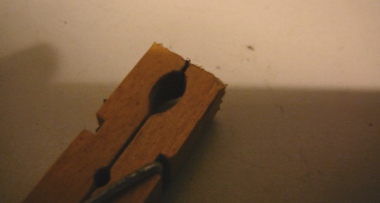
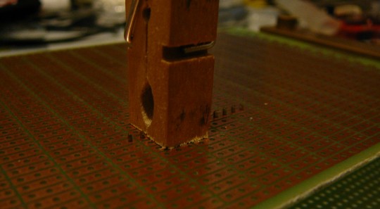
1 : Grab a header pin in a clothes-peg and cut the peg while holding it in a (regular) vise
![]()
![]()
2: or just attach the header with two of those black pin spacers.
![]()
Full Metal Stickvise
Made my own Stickvise from some pieces of brass and aluminium I found in the cheap scraps at the local metal supplier, and some stock I had.