Michael Ratcliffe
-
Pesticide Doser, Cheap DIY Mister or Humidifyer
09/16/2015 at 17:46 • 0 commentsIn one of my other blog video's I showed you my infestation of butterfly and caterpillars. It is a heavy infestation and will be a hard one to eradicate.
This Blog will cover how to make a cheap DIY pesticide doser that will reach every small nook and cranny of your grow room to really get on top of a heavy pest problem. I have used this many times in the past with great success after traditional spraying failed in my grow rooms, chicken pens and kennels. It could also be used with pure water for any humidifying , fog, misting needs.
![]()
What you will need:
[The Prices are estimates]
>24v Ultrasonic Mister [£2]
[You may want multiple units for large rooms/ large amounts of mist]
![Mister]()
>24v Power supply
Any source of 24V DC, make sure it can supply enough current for your planned number of misters and Fan.
Misters have a female 5.5mm Power jack [common size for wall mounted power supplies]
>24v PC Fan £1
![24v Fan]()
> A Container Of your Choice with removable LID [Wide and shallow is better]
>Fan Speed Controller [Optional] £2
The basic ones just work as a voltage divider, so you can make your own from a potentiometer if you like.
![Optional]()
>5.5mm 12v splitter cable [Optional] £2
![4]()
How to build it:
As Always this is just a set of instructions, follow them at your won risk.
>I'm not including a wiring diagram with this blog, everything operates at the same voltage and it is as simple as wiring all parts in parallel.
>Cut 4 holes in the top of the container you plan to use, two the size of the fan you selected and two smaller ones for the waterproof bungs on the mister wires.
>Mount the fan so it is blowing air into the container [stops the motor getting wet] and alter the mister lead length in the bungs to place them in the middle of the container away from your inlet and exhaust holes.
>Add a exhaust pipe if you want to direct the mist to somewhere else.
How To use:
As a General Mister:
or humidifier to keep cool in summer or for a Halloween project, just add water power it on and let it do its thing, use the fan controller knob to control the amount of mist you want.
As a Pesticide Doser:
>Best to do this over night so the plants are less stressed
>Close all windows, shut of exhaust fans [make it a closed system]
>Fill the tub with the water soluble pestacide of your choice [see link below for a home made nicotine based pestacide]
>Turn the mister on and leave the room imediatly, check it is not leaking into places with people/ pets
>Come back int he morning, re open the windows and the live bugs should be gone.
>Repeat every few days to kill the new larva before they get the chance to lay eggs.
>A few repetitions usually work, if there is no effect change the type of pesticide, your pest might have become immune to your choice of poison.
You want the room to be cleaned to be full of mist, add extra ultrasonic misters as you need them if your room is large, position it so you get the best distribution of mist/fog.
If you are using this in an aquaponics system make sure to use a pesticide that is fish safe!
Here is my preferred "natural" Pesticide of choice, I usually use this first and seek alternatives if it does not work:
How to make a nicotine insecticide | eHow UK
Good Luck staying Pest Free, this is just my preferred method for heavy infestations, there are many other ways to achieve the same goal.
-
Updated Uptime Counter
09/12/2015 at 16:28 • 6 commentsThis is an updated version of the uptime counter here:
This one also takes into account the rollover of the timers at 50 days, so it will give a estimate of uptime for a very long time [years].
/* This Script is the bare bones needed to Keep a Uptime counter that will survive the 50 day timer rollover This will not give a uptime of great accuracy over long periods, but it will let you see if your arduino has reset if you want better accuracy, pull the Unix time from the IOT, External RTC or GPS module Also Reconnecting the serial com's will reset the arduino. So this is mainly useful for a LCD screen Michael Ratcliffe Mike@MichaelRatcliffe.com This program is free software: you can redistribute it and/or modify it under the terms of the GNU General Public License as published by the Free Software Foundation, either version 3 of the License, or (at your option) any later version. This program is distributed in the hope that it will be useful, but WITHOUT ANY WARRANTY; without even the implied warranty of MERCHANTABILITY or FITNESS FOR A PARTICULAR PURPOSE. See the GNU General Public License for more details. You should have received a copy of the GNU General Public License along with this program. If not, see . */ //************************** Just Some basic Definitions used for the Up Time LOgger ************// long Day=0; int Hour =0; int Minute=0; int Second=0; int HighMillis=0; int Rollover=0; //************** Setup routine - Runs once at power up **************************// void setup(){ Serial.begin(9600); // starting Serial Com's }; //****** Main Loop - Put your Code Here ********************// void loop(){ uptime(); //Runs the uptime script located below the main loop and reenters the main loop print_Uptime(); delay(500); }; //************************ Uptime Code - Makes a count of the total up time since last start ****************// void uptime(){ //** Making Note of an expected rollover *****// if(millis()>=3000000000){ HighMillis=1; } //** Making note of actual rollover **// if(millis()<=100000&&HighMillis==1){ Rollover++; HighMillis=0; } long secsUp = millis()/1000; Second = secsUp%60; Minute = (secsUp/60)%60; Hour = (secsUp/(60*60))%24; Day = (Rollover*50)+(secsUp/(60*60*24)); //First portion takes care of a rollover [around 50 days] }; //******************* Prints the uptime to serial window **********************// void print_Uptime(){ Serial.print(F("Uptime: ")); // The "F" Portion saves your SRam Space Serial.print(Day); Serial.print(F(" Days ")); Serial.print(Hour); Serial.print(F(" Hours ")); Serial.print(Minute); Serial.print(F(" Minutes ")); Serial.print(Second); Serial.println(F(" Seconds")); }; -
Three Dollar EC - PPM Meter [Arduino]
09/04/2015 at 13:56 • 154 commentsThis Blog will Cover How to build a cheap EC meter for your aquaponics/Hydroponics or water quality related projects. We are not going to get into what the ideal value of PPM or EC is, Just cover how to measure and quantify a fluid.
We will be using this for the Urine based aquaponics unit, we need to be able to control the strength of the growing fluid in the system but for the person on a budget a EC meter is just to much money. the Solution a $3 EC Meter for any Arduino.
You can use this to measure drinking water quality to with a small change to the code and changing R1 [see below].
Parts:
-MCU of your choice with ADC
-DS18B20 waterproof temperature sensor
-500 ohm [or 1kohm resistor]
-Type A Two Prong american plug to Figure 8
-Female Socket for Figure 8 connector
So why are we using a plug:
-Cheap
-Available worldwide
-Standard size [makes calibration easy]
Use the solid prong one like below and not the one with holes:
![images.jpg]()
Wiring it up:
Note: You want the Solid Prong type plug
Do not Plug the pronged plug into the mains
![Pinout.png]()
Operating Principal
PPM is calculated from the EC of a fluid, EC is the inverse of the electrical resistance of the fluid. We are estimating the EC or PPM of a fluid by measuring the resistance between two probes [The plug pins] when the plug is submerged in the liquid of interest.
Ec measurement needs to be done using AC or the liquid of interest is polarised and will give bad readings. This has got to be a great example of asking why instead of just accepting a statement as fact, it turns out we can take a very fast DC reading without suffering polarisation. meaning we can make a really cheap EC sensor.
Want to use it and dont care how it works? Skip to the main EC code and using the wiring diagram it will work.
Temperature Compensation
Temperature has an effect on the conductivity of fluids so it is essential that we compensate for this.
It is common to use a liner approximation for small temperature changes[1] to convert them to their equivelant EC at 25*C:
EC25 = EC /( 1 + a (T - 25) )
EC25- Equivelant EC at 25'C
EC - Measured EC
T- Temperature [Decgrees C] of Measurment
a = 0.019 °C [Commonly used for nutrient solutions]
Deciding on Value of R1
//##################################################################################
//----------- Do not Replace R1 with a resistor lower than 300 ohms ------------
//##################################################################################
We can change the Value of R1 in the voltage divider to change the range of EC we want to measure. Below is the Equivalent Voltage divider circuit.
![Voltage Divider.png]()
Ra
Ra the resistance of the digital pins is not stated in the data sheet instead we need to pull it out from a graph.
Going off the graph on page [387] of the atmel 2560 Data Sheet “Figure 32-25. I/O Pin Output Voltage vs. Source Current (VCC = 5V)”
V=IR
Ra= V/I [From Figure] V=0.4 I=1.5e-4 R=25 ohms estimated
Rc
Rc will change with EC [PPM] of the measured fluid. we will calculate the maximum and minimum values we expect to see for the range of fluids we wish to measure taking into account temperature changes and the cell constant K. [We will estimate K to be 3 for the plug probe, estimate from previous tests]EC = EC25*( 1 + a (T - 25))
R=(1000/(EC*K)) +Ra
Min temp=0 [we arnt going to care about EC if the pond is frozen]
Max Temp = 40 *C [I doubt a pond should be above this]
Minimum EC 25=0.3 EC= 0.3*(1+0.019*(0-25) Min EC= 0.16 S/sm
Maximum EC 25= 3 EC= 0.3*(1+0.019*(40-25) Max EC = 3.9 S/cm
Min Resistance = 1000/(MaxEC*K)+25 = 1000(3.9*2.88) =114 ohms
Max Resitance = 1000/(MinEC*K)+25 = 1000/(0.16*2.88) = 2195 ohms
R1
Now we have enough information to calculate a good value for R1 to get the best resolution over our intended measuring range. We could sum it all up mathematically and differentiate to find the peak, but that hurts my head so I just did a quick excel spreadsheet for the Voltage divider for the EC I expect to see:
![Exel.png]()
As we can see we get the largest difference using a value for R1 of 500 ohm, I only had 1Kohm to hand so I will have to live with a little less range.So we chose a 500 ohm resistor
EC – Range /Voltage Range * (5/ADC steps)
(3.9-0.16)/3.14 * 5/1024 = 5.8e-3 resolution so that is a resolution of 0.0058
To put this is PPM [Tranchen [Australia] PPMconversion: 0.7] this is a resolution of 4ppm.
Much more than we need for aquaponics or hydroponics.
If you want to measure the quality of drinking water you will need to calculate the expected Ec values and increase R1 accordingly.
Calibration Code
If you want the best readings from your system it is advisable to calibrate your sensor with some known fluid. But If you dont need to if you use the plug probe shown above, it will still work well.
>Add your EC in S/cm into the definitions
>Plug your K value from the terminal window into the main EC code
you will need to use the modified one wire and Dallas library [download from www.michaelratcliffe.com] or add a pull up for the temperature probe data line [google it]
/*
  ElCheapo Arduino EC-PPM measurments Calibration

  This Script is used for calibration of the sensor and fine tuning of the Cell Constant K
  Submerge the sensor and temperature probe in the calibration solution and leave for a while so the temperature probe can settle
  Change the value of the calibration solution to suit the solutiton strength
  Stir the probe to make sure the solution is well mixed and upload the code to the arduino
  Open the terminal for an update of the estimated Cell Constant K [should be around 3] and use this new value in the main EC code.


  28/8/2015  Michael Ratcliffe  Mike@MichaelRatcliffe.com


          This program is free software: you can redistribute it and/or modify
    it under the terms of the GNU General Public License as published by
    the Free Software Foundation, either version 3 of the License, or
    (at your option) any later version.


    This program is distributed in the hope that it will be useful,
    but WITHOUT ANY WARRANTY; without even the implied warranty of
    MERCHANTABILITY or FITNESS FOR A PARTICULAR PURPOSE.  See the
    GNU General Public License for more details.


    You should have received a copy of the GNU General Public License
    along with this program.  If not, see .

    Parts:
    -Arduino - Uno/Mega
    -Standard American two prong plug
    -1 kohm resistor
    -DS18B20 Waterproof Temperature Sensor


    See www.MichaelRatcliffe.com/Projects for a Pinout and user guide or consult the Zip you got this code from

*/


//************************** Libraries Needed To Compile The Script [See Read me In Download] ***************//
// Both below Library are custom ones [ SEE READ ME In Downloaded Zip If You Dont Know how To install Use them or add a pull up resistor to the temp probe


#include <OneWire.h>
#include <DallasTemperature.h>


//************************* User Defined Variables ********************************************************//


float CalibrationEC=1.38; //EC value of Calibration solution is s/cm


//##################################################################################
//-----------  Do not Replace R1 with a resistor lower than 300 ohms    ------------
//##################################################################################


int R1= 1000;
int Ra=25; //Resistance of powering Pins
int ECPin= A0;
int ECGround=A1;
int ECPower =A4;


//*************Compensating for temperature ************************************//
//The value below will change depending on what chemical solution we are measuring
//0.019 is generaly considered the standard for plant nutrients [google "Temperature compensation EC" for more info
float TemperatureCoef = 0.019; //this changes depending on what chemical we are measuring


//************ Temp Probe Related *********************************************//
#define ONE_WIRE_BUS 10          // Data wire For Temp Probe is plugged into pin 10 on the Arduino
const int TempProbePossitive =8;  //Temp Probe power connected to pin 9
const int TempProbeNegative=9;    //Temp Probe Negative connected to pin 8


//***************************** END Of Recomended User Inputs *****************************************************************//


OneWire oneWire(ONE_WIRE_BUS);// Setup a oneWire instance to communicate with any OneWire devices
DallasTemperature sensors(&oneWire);// Pass our oneWire reference to Dallas Temperature.


float TemperatureFinish=0;
float TemperatureStart=0;
float EC=0;
int ppm =0;


float raw= 0;
float Vin= 5;
float Vdrop= 0;
float Rc= 0;
float K=0;


int i=0;
float buffer=0;


//*********************************Setup - runs Once and sets pins etc ******************************************************//
void setup()
{
  Serial.begin(9600);
  pinMode(TempProbeNegative , OUTPUT ); //seting ground pin as output for tmp probe
  digitalWrite(TempProbeNegative , LOW );//Seting it to ground so it can sink current
  pinMode(TempProbePossitive , OUTPUT );//ditto but for positive
  digitalWrite(TempProbePossitive , HIGH );
  pinMode(ECPin,INPUT);
  pinMode(ECPower,OUTPUT);//Setting pin for sourcing current
  pinMode(ECGround,OUTPUT);//setting pin for sinking current
  digitalWrite(ECGround,LOW);//We can leave the ground connected permanantly

  delay(100);// gives sensor time to settle
  sensors.begin();
  delay(100);
  //** Adding Digital Pin Resistance to [25 ohm] to the static Resistor *********//
  // Consule Read-Me for Why, or just accept it as true
  R1=(R1+Ra);

  Serial.println("ElCheapo Arduino EC-PPM measurments Calibration");
  Serial.println("By: Michael Ratcliffe  Mike@MichaelRatcliffe.com");
  Serial.println("Free software: you can redistribute it and/or modify it under GNU ");
  Serial.println("");
  Serial.println("Make sure Probe and Temp Sensor are in Solution and solution is well mixed");
  Serial.println("");
  Serial.println("Starting Calibration: Estimated Time 60 Seconds:");


};
//******************************************* End of Setup **********************************************************************//


//************************************* Main Loop - Runs Forever ***************************************************************//
//Moved Heavy Work To subroutines so you can call them from main loop without cluttering the main loop
void loop()
{


  i=1;
  buffer=0;
sensors.requestTemperatures();// Send the command to get temperatures
TemperatureStart=sensors.getTempCByIndex(0); //Stores Value in Variable


//************Estimates Resistance of Liquid ****************//
while(i<=10){


digitalWrite(ECPower,HIGH);
raw= analogRead(ECPin);
raw= analogRead(ECPin);// This is not a mistake, First reading will be low
digitalWrite(ECPower,LOW);
buffer=buffer+raw;
i++;
delay(5000);
};
raw=(buffer/10);


sensors.requestTemperatures();// Send the command to get temperatures
TemperatureFinish=sensors.getTempCByIndex(0); //Stores Value in Variable


//*************Compensating For Temperaure********************//
EC =CalibrationEC*(1+(TemperatureCoef*(TemperatureFinish-25.0))) ;

//***************** Calculates R relating to Calibration fluid **************************//
Vdrop= (((Vin)*(raw))/1024.0);
Rc=(Vdrop*R1)/(Vin-Vdrop);
Rc=Rc-Ra;
K= 1000/(Rc*EC);


Serial.print("Calibration Fluid EC: ");
Serial.print(CalibrationEC);
Serial.print(" S  ");  //add units here
Serial.print("Cell Constant K");
Serial.print(K);


if (TemperatureStart==TemperatureFinish){
  Serial.println("  Results are Trustworthy");
  Serial.println("  Safe To Use Above Cell Constant in Main EC code");

}
else{
  Serial.println("  Error -Wait For Temperature To settle");

}


}
//************************************** End Of Main Loop **********************************************************************//
EC PPM Measurement Code
>If you are using PPM and not EC make sure you note what conversion factor you are using [it isnt universal]
>Dont call the read function more than once every 5 seconds or you will get bad readings and a damaged probe
I tested this code in a solution for 48 hours reading at 5 second intervals without any polarisation or probe damage, the longer you leave between readings the longer your probe will last. 5 seconds is the minimum wait between readings not the maximum.
you will need to use the modified one wire and Dallas library [download from www.michaelratcliffe.com] or add a pull up for the temperature probe data line [google it]
/*
  ElCheapo Arduino EC-PPM measurments

  This scrip uses a common USA two prong plug and a 47Kohm Resistor to measure the EC/PPM of a Aquaponics/Hydroponics Sytem.
  You could modift this code to Measure other liquids if you change the resitor and values at the top of the code.

  This Program will give you a temperature based feed controller. See Read me in download file for more info.

  28/8/2015  Michael Ratcliffe  Mike@MichaelRatcliffe.com


          This program is free software: you can redistribute it and/or modify
    it under the terms of the GNU General Public License as published by
    the Free Software Foundation, either version 3 of the License, or
    (at your option) any later version.


    This program is distributed in the hope that it will be useful,
    but WITHOUT ANY WARRANTY; without even the implied warranty of
    MERCHANTABILITY or FITNESS FOR A PARTICULAR PURPOSE.  See the
    GNU General Public License for more details.


    You should have received a copy of the GNU General Public License
    along with this program.  If not, see .

    Parts:
    -Arduino - Uno/Mega
    -Standard American two prong plug
    -1 kohm resistor
    -DS18B20 Waterproof Temperature Sensor

    Limitations:
    -
    -

    See www.MichaelRatcliffe.com/Projects for a Pinout and user guide or consult the Zip you got this code from

*/


//************************** Libraries Needed To Compile The Script [See Read me In Download] ***************//
// Both below Library are custom ones [ SEE READ ME In Downloaded Zip If You Dont Know how To install] Use them or add a pull up resistor to the temp probe


#include <OneWire.h>
#include <DallasTemperature.h>


//************************* User Defined Variables ********************************************************//


//##################################################################################
//-----------  Do not Replace R1 with a resistor lower than 300 ohms    ------------
//##################################################################################


int R1= 1000;
int Ra=25; //Resistance of powering Pins
int ECPin= A0;
int ECGround=A1;
int ECPower =A4;


//*********** Converting to ppm [Learn to use EC it is much better**************//
// Hana      [USA]        PPMconverion:  0.5
// Eutech    [EU]          PPMconversion:  0.64
//Tranchen  [Australia]  PPMconversion:  0.7
// Why didnt anyone standardise this?


float PPMconversion=0.7;


//*************Compensating for temperature ************************************//
//The value below will change depending on what chemical solution we are measuring
//0.019 is generaly considered the standard for plant nutrients [google "Temperature compensation EC" for more info
float TemperatureCoef = 0.019; //this changes depending on what chemical we are measuring


//********************** Cell Constant For Ec Measurements *********************//
//Mine was around 2.9 with plugs being a standard size they should all be around the same
//But If you get bad readings you can use the calibration script and fluid to get a better estimate for K
float K=2.88;


//************ Temp Probe Related *********************************************//
#define ONE_WIRE_BUS 10          // Data wire For Temp Probe is plugged into pin 10 on the Arduino
const int TempProbePossitive =8;  //Temp Probe power connected to pin 9
const int TempProbeNegative=9;    //Temp Probe Negative connected to pin 8


//***************************** END Of Recomended User Inputs *****************************************************************//


OneWire oneWire(ONE_WIRE_BUS);// Setup a oneWire instance to communicate with any OneWire devices
DallasTemperature sensors(&oneWire);// Pass our oneWire reference to Dallas Temperature.


float Temperature=10;
float EC=0;
float EC25 =0;
int ppm =0;


float raw= 0;
float Vin= 5;
float Vdrop= 0;
float Rc= 0;
float buffer=0;


//*********************************Setup - runs Once and sets pins etc ******************************************************//
void setup()
{
  Serial.begin(9600);
  pinMode(TempProbeNegative , OUTPUT ); //seting ground pin as output for tmp probe
  digitalWrite(TempProbeNegative , LOW );//Seting it to ground so it can sink current
  pinMode(TempProbePossitive , OUTPUT );//ditto but for positive
  digitalWrite(TempProbePossitive , HIGH );
  pinMode(ECPin,INPUT);
  pinMode(ECPower,OUTPUT);//Setting pin for sourcing current
  pinMode(ECGround,OUTPUT);//setting pin for sinking current
  digitalWrite(ECGround,LOW);//We can leave the ground connected permanantly

  delay(100);// gives sensor time to settle
  sensors.begin();
  delay(100);
  //** Adding Digital Pin Resistance to [25 ohm] to the static Resistor *********//
  // Consule Read-Me for Why, or just accept it as true
  R1=(R1+Ra);// Taking into acount Powering Pin Resitance

  Serial.println("ElCheapo Arduino EC-PPM measurments");
  Serial.println("By: Michael Ratcliffe  Mike@MichaelRatcliffe.com");
  Serial.println("Free software: you can redistribute it and/or modify it under GNU ");
  Serial.println("");
  Serial.println("Make sure Probe and Temp Sensor are in Solution and solution is well mixed");
  Serial.println("");
  Serial.println("Measurments at 5's Second intervals [Dont read Ec morre than once every 5 seconds]:");


};
//******************************************* End of Setup **********************************************************************//


//************************************* Main Loop - Runs Forever ***************************************************************//
//Moved Heavy Work To subroutines so you can call them from main loop without cluttering the main loop
void loop()
{


GetEC();          //Calls Code to Go into GetEC() Loop [Below Main Loop] dont call this more that 1/5 hhz [once every five seconds] or you will polarise the water
PrintReadings();  // Cals Print routine [below main loop]


delay(5000);


}
//************************************** End Of Main Loop **********************************************************************//


//************ This Loop Is called From Main Loop************************//
void GetEC(){


//*********Reading Temperature Of Solution *******************//
sensors.requestTemperatures();// Send the command to get temperatures
Temperature=sensors.getTempCByIndex(0); //Stores Value in Variable


//************Estimates Resistance of Liquid ****************//
digitalWrite(ECPower,HIGH);
raw= analogRead(ECPin);
raw= analogRead(ECPin);// This is not a mistake, First reading will be low beause if charged a capacitor
digitalWrite(ECPower,LOW);


//***************** Converts to EC **************************//
Vdrop= (Vin*raw)/1024.0;
Rc=(Vdrop*R1)/(Vin-Vdrop);
Rc=Rc-Ra; //acounting for Digital Pin Resitance
EC = 1000/(Rc*K);


//*************Compensating For Temperaure********************//
EC25  =  EC/ (1+ TemperatureCoef*(Temperature-25.0));
ppm=(EC25)*(PPMconversion*1000);


;}
//************************** End OF EC Function ***************************//


//***This Loop Is called From Main Loop- Prints to serial usefull info ***//
void PrintReadings(){
Serial.print("Rc: ");
Serial.print(Rc);
Serial.print(" EC: ");
Serial.print(EC25);
Serial.print(" Simens  ");
Serial.print(ppm);
Serial.print(" ppm  ");
Serial.print(Temperature);
Serial.println(" *C ");


/*
//********** Usued for Debugging ************
Serial.print("Vdrop: ");
Serial.println(Vdrop);
Serial.print("Rc: ");
Serial.println(Rc);
Serial.print(EC);
Serial.println("Siemens");
//********** end of Debugging Prints *********
*/
};
Got any questions let me know.
The next tutorial will be on coding a self learning nutrient doser.
References:
[1]
John J. Barron & Colin Ashton "The Effect of Temperature on Conductivity Measurement" Technical Services Department, Reagecon Diagnostics Ltd
http://www.reagecon.com/pdf/technicalpapers/Effect_of_Temperature_TSP-07_Issue3.pdf
-
Arduino Hall Effect Water Flow Meter
08/28/2015 at 00:12 • 2 commentsWhile the fish feeder project is on hold awaiting parts, we will take some time to work on the other aspects of this project. The Aquaopnics side using fly's as food and the PeePonics both need to be studied in detail. for both of these we will need a good idea about the amout of water consumed.
I am sure a lot of you are also working on ways to keep an eye on water flow, So I thought I would make a blog covering my implementation.
I opted for a hall effect flow meter because I salvaged it a while ago and had it handy. It has been up and running in the greenhouse for a while now as part of a larger code, Ive pulled the meter portion out and it is below, I've got no spare arduino to test it works but it is pretty simple [Point out any problems you see].
How It works:
I dont like the approach of measuring the frequency to calculate flow rate and then integrating to get water flow, So It works the opposite way.
>ISR to log number of pulses
>Convert the Pulses/second for a flow rate
>Logs Total Pulses for total water usage
>Checks there isnt a major leak [flow rate is reduced because I use drip irrigation]
![Pinout.png]()
Things to keep in mind, the serial will reset every time you reconnect so it isnt goof for final implementation, the clock will roll-over every 50 days and could output one bad reading every 50 days.
The Code:
/* This script is used to make sense of the output from a hall effect water flow meter and make a note of any problems


Michael Ratcliffe  Mike@MichaelRatcliffe.com

    This program is free software: you can redistribute it and/or modify
    it under the terms of the GNU General Public License as published by
    the Free Software Foundation, either version 3 of the License, or
    (at your option) any later version.


    This program is distributed in the hope that it will be useful,
    but WITHOUT ANY WARRANTY; without even the implied warranty of
    MERCHANTABILITY or FITNESS FOR A PARTICULAR PURPOSE.  See the
    GNU General Public License for more details.


    You should have received a copy of the GNU General Public License
    along with this program.  If not, see .


    Components:
    See main folder for sensor data sheets, required liabaries and extra information: [can be downloaded via www.michaelratcliffe.com]

    All power systems should be powerd of DC voltage of below 48v for safter [water is around] 12v is prefferable and cheapest. As always this is a DIY project and done at your own risk.


    >Arduino Mega 2560 [1280 is not sutiable, ram problems and sensor conflict] compiled using Arduino 1:1.0.5
    >Hall Effect Water Flow Meter 5v


*/
//******************************** User Defined Variables *******************************************************//
#define Meter_power  5
#define Meter_ground 4
#define Water_pin 3


float Click_Per_L = 300; // this depends on your flow meter


const float Max_ExpectedFlow =2; //Max flow expected flowrate in L/s, if it is more than this we have a problem


//***************************** End Of User Defined Variables **************************************************//


unsigned long PulseCount=0;  //counter for water meter pulses
long Second;
long Last_Reading=0;
int Readings=0;
float Water_Used=0;
float Flow_Rate= 0;
long Last_Count =0;


int BurstPipe=0;


//**************************** Setup Routine , Runs Once and Sets used pins to correct value *******************//
void setup() {

pinMode(Meter_ground, OUTPUT);
digitalWrite(Meter_ground, LOW);

pinMode( Meter_power, OUTPUT);
digitalWrite(Meter_power, HIGH);

pinMode(Water_pin, INPUT);
digitalWrite(Water_pin, HIGH);// saves having an external pullup

//External Interrupts:  3 (interrupt 1),
attachInterrupt(1, WaterCounter, FALLING);  //watermeter pulse output connected to pin3
};


//************************************** Main Loop that will continualy run ******************************************//
void loop(){

Second=millis()/1000;


//************** If Statment that will run every second ******************//
            if (Last_Reading!=Second) {
            Last_Reading=Second; //Makes note of the last second
            Readings=1;          //Tell serial there is data to transmit
            Flow_Rate=((PulseCount-Last_Count)/Click_Per_L);


            Water_Used=(1/(Click_Per_L/PulseCount)); //cant recall why I did it this way, maybe to retain float capabilities
            Last_Count=PulseCount;                   // Makes a note of the last reading

                               //** Checks if there is a problem **//
                                  if(Flow_Rate>=Max_ExpectedFlow){
                                                       BurstPipe=1;
                                                                  };


                                    };


//**** Checks If there is Data To send over Serial- Recomended to be LCD instead ******//
if (Readings==1){
Readings=0;

Serial.print("Total Water Used");
Serial.print(Water_Used);
Serial.println(" L");
Serial.print("Current Flow Rate: ");
Serial.print(Flow_Rate);
  Serial.println(" L/s");

          if(BurstPipe==1){
            Serial.println("BurstPipe");
          }


}


delay(10);
};
//*************************************************END OF LOOP ******************************************************//


//***Interupt routine for water meter readings - Runs everytime sensor has a pulse ***//


void WaterCounter() {

   // Increment the pulse counter
  PulseCount++;

};
Recommendations: Add a LCD/ IOT solution to remove the serial resetting problem, add a uptime counter.
-
Just A Few Useful Arduino Hacks: SRAM & Uptime
08/28/2015 at 00:07 • 6 commentsThe Next Blog is about a water usage monitor, the total usage is a great readout to have but how can we trust it? We could poll the data to IOT Mysql database, or to an sd card, but maybe that is not available for the project and we just need something simple.
Uptime Counter
It is useful to have an uptime counter on the arduino so we are aware of any recent resets. Mainly because we need to be aware of any problems making it reset and know that any readouts for totals [ie water usage] are not a true representation.
Checking SRam Ussage
Sram ussage isnt really a problem if we are making a small script, but there will come a time when your script grows and you need to be aware of running out of Sram and need to refine the code to reduce how much we are relying on the SRam.
A Sram shortage will cause a code to hang randomly.
On any large code it is a good idea to have a readout of the Maximum used Ram, and either make the operator aware of it or simply reset the controller. The code measures the amount of Sram used and sets a flag "Ram_error=1" if we exeed 70%.
UpTime Counter:
A better updated version can be seen here:
/* This Script is the bare bones needed to Keep a Uptime counter that will survive the 50 day timer rollover
This will not give a uptime of great accuracy over long periods, but it will let you see if your arduino has reset
if you want better accuracy, pull the Unix time from the IOT, External RTC or GPS module
Also Reconnecting the serial com's will reset the arduino. So this is mainly useful for a LCD screen


Michael Ratcliffe  Mike@MichaelRatcliffe.com

    This program is free software: you can redistribute it and/or modify
    it under the terms of the GNU General Public License as published by
    the Free Software Foundation, either version 3 of the License, or
    (at your option) any later version.


    This program is distributed in the hope that it will be useful,
    but WITHOUT ANY WARRANTY; without even the implied warranty of
    MERCHANTABILITY or FITNESS FOR A PARTICULAR PURPOSE.  See the
    GNU General Public License for more details.


    You should have received a copy of the GNU General Public License
    along with this program.  If not, see .


*/


//************************** Just Some basic Definitions used for the Up Time LOgger ************//
long Day=0;
int Hour =0;
int Minute=0;
int Second=0;
int SecondStamp=0;
int Once=0;


//************** Setup routine - Runs once at power up **************************//
void setup(){
Serial.begin(9600); // starting Serial Com's

};


//****** Main Loop - Put your Code Here ********************//
void loop(){

uptime(); //Runs the uptime script located below the main loop and reenters the main loop
};


//************************ Uptime Code - Makes a count of the total up time since last start ****************//
//It will work for any main loop's, that loop moret han twice a second: not good for long delays etc
void uptime(){
//** Checks For a Second Change *****//
if(millis()%1000<=500&&Once==0){
SecondStamp=1;
Once=1;
}
//** Makes Sure Second Count doesnt happen more than once a Second **//
if(millis()%1000>500){
Once=0;
}


                         if(SecondStamp==1){
                           Second++;
                           SecondStamp=0;
                           print_Uptime();

                         if (Second==60){
                          Minute++;
                          Second=0;
                          if (Minute==60){
                          Minute=0;
                          Hour++;

                         if (Hour==24){
                          Hour=0;
                          Day++;
                         }
                         }
                         }
                         };


};


//******************* Prints the uptime to serial window **********************//
void print_Uptime(){

  Serial.print(F("Uptime: ")); // The "F" Portion saves your SRam Space
  Serial.print(Day);
  Serial.print(F("  Days  "));
  Serial.print(Hour);
  Serial.print(F("  Hours  "));
  Serial.print(Minute);
  Serial.print(F("  Minutes  "));
  Serial.print(Second);
  Serial.println(F("  Seconds"));
};
SRam Code:
/*

Based on the work of:


This Scrip includes the basics for measuring the Ram ussage of a script and displays it as a Percentage to the serial window
It is usefull for including in larger sketches where you could run out of ram
This script checks the Ram usage and sets a flag "Ram_error" if we are ussing more than 70% of it


Michael Ratcliffe  Mike@MichaelRatcliffe.com

    This program is free software: you can redistribute it and/or modify
    it under the terms of the GNU General Public License as published by
    the Free Software Foundation, either version 3 of the License, or
    (at your option) any later version.


    This program is distributed in the hope that it will be useful,
    but WITHOUT ANY WARRANTY; without even the implied warranty of
    MERCHANTABILITY or FITNESS FOR A PARTICULAR PURPOSE.  See the
    GNU General Public License for more details.


    You should have received a copy of the GNU General Public License
    along with this program.  If not, see .

*/


//************************* Change Value Below For Board Of Choice ***********************//
/* ATMega168 ATMega328P ATmega1280 ATmega2560
SRAM 1024 bytes 2048 bytes 8192 Bytes 8192 Bytes
*/


const int Total_Ram = 8192; //change this value for the correct one from above data


//****************************Seting up the Ram check**************************************//
int freeRam () {
extern int __heap_start, *__brkval;
int v;
return (int) &v - (__brkval == 0 ? (int) &__heap_start : (int) __brkval);
};


//********Just Some variables we use to convert to % ************//
float Ram=3;
float Ram_Ussage=0;
int Ram_error=0;


//***** Setup, Ran once to startserial com's *******************//
void setup() {
  Serial.begin(9600);


}


//*******************Main Loop, Put your code Here **************************//
void loop (){
Max_Ram();  // We need to call this at multiple points in the main loop,  Sram Ussage will change thru the loop


Serial.print("Ram Used:");
Serial.print(Ram_Ussage);
Serial.println("%");

if(Ram_error==1){
   Serial.print("LOW RAM WARNING");
    }

delay(100);

};


//*************** End Of Main Loop *****************************************//


//************* Loop for calculating Ram Ussage, called from main loop***//

    void Max_Ram(){

            if(freeRam()>=Ram){
             Ram=(freeRam());
             Ram_Ussage=(((Total_Ram-Ram)/Total_Ram)*100);
                              };

             if(Ram_Ussage>=70){
              Ram_error=1; // Use this set flag to warn the user of a potential Ram ussage problem, or reset the arduino if it becomes true
                              };


};
As usuall these codes will be avalible to download from: www.MichaelRatcliffe/Projects
-
Great News
08/24/2015 at 14:02 • 0 commentsThe Project has made it into the top 100 proceeding to the next round.
I am still working on the project, and will be posting updates as they are ready.
If any entity feels like helping me along the way I shipped all of my parts to HAD and could do with a few Arduino Uno's, another 2b Pi and a few other components to take the project to the next stage.
The next few Updates will be about automating the feed spacing of conventional feeders and starting to investigate the alternative inputs side.
Keep Watching,
Mike
-
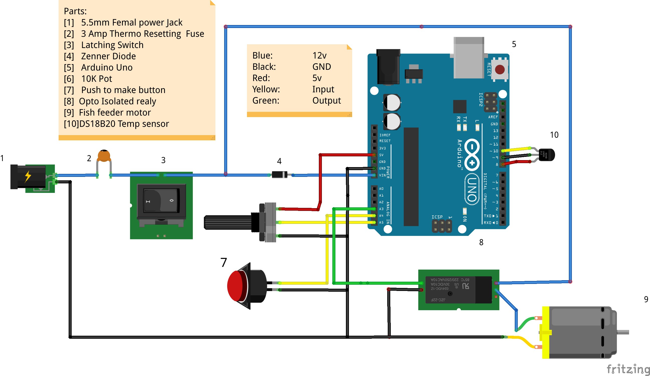
Temperature Compensating Arduino Feed Controller
08/20/2015 at 23:21 • 0 commentsWell I have caught up on my sleep and its back to working on the project.
This Update contains the wiring diagram and code for the temperature compensated feeder. This code is enough for you to make a unit to test if it works for you. I am pulling my time of day from another MCU running in the greenhouse, I advice wiring in a gps unit if you are making this a standalone unit.I will be doing a tutorial on this and how we use the time for regulating feeding timings in the near future.
The Wiring diagram:
![]()
Important Notes:
>You will need a suitable 12v power supply for your feeder
-12v 1 amp for the 20mm feeder & 12v 4 amp for the 25mm feeder
>Dont forget the Diode [4] we are bypassing the reverse voltage protection by supplying power to the Vin Pin
>We dont need to use a pull down resistor on the DS18B20 because we are using a modified 1-wire library
>Flip the Wires to the Feeder Motor if yours is running in reverse
>Put this controller into a waterproof housing if you plan on using it long term
The Code
Go to www.MichaelRatcliffe.com/Projects and find the Zip containing the code for the Temperature based Feeder and open the Read ME.
/*
   Automated Fish Feeder:

   This Program will give you a temperature based feed controller. See Read me in download file for more info.
   4/8/2015  Michael   Ratcliffe


          This program is free software: you can redistribute it and/or modify
    it under the terms of the GNU General Public License as published by
    the Free Software Foundation, either version 3 of the License, or
    (at your option) any later version.

    This program is distributed in the hope that it will be useful,
    but WITHOUT ANY WARRANTY; without even the implied warranty of
    MERCHANTABILITY or FITNESS FOR A PARTICULAR PURPOSE.  See the
    GNU General Public License for more details.

    You should have received a copy of the GNU General Public License
    along with this program.  If not, see .

 */

//************************** Libraries Needed To Compile The Script [See Read me In Download] ***************//

#include <OneWire.h> // We Need This Libaray To Read The Temperature Sensor, SEE READ ME In Downloaded Zip If You Dont Know how To install This
#include <DallasTemperature.h>


//************** User Defined Variables *******************************//
/*
Alter your variables by changinf the numbers below, they only aceept whole numbers

*/

long feedSpacing =60; //the time between feeds in mnuits
const int FeedsPerDay =24;  //Change this only is you change the feeding interval or total number of feeds a day


long MinWeight =5; //Minimum Weight [Kg] Of Fish You Want The Potentiometer To Represent
long  MaxWeight =20;//Maximum Wight [Kg] Of Fish You Want The Potentiometer To Represent
const int FeedRate=8.3; // g/s How Much Feed in Grams Your Feeder Dispnces In A Second [You need to Work This out]


int PercentTenC =3;  //percent of Body weight to feed fish daily at 10*C
int PercenTwentSixC=12;//Percent of Body weight to feed fish daily at 26*C

 int  MaxFeedPercent=16;
 int MinFeedPercent=1;    //InCase The Sensor Breaks, We Will StillFeed Them a Minimum Amount

// The Ones Below Should Be ok as they are, unless your Relay uses pull Low Triggers
const int  OFF=1;
const int ON=0;


//****************** End Of User Variables ***************************//


//************ ONLY Cange These Values Below If You Have Wired To different Pins *****///


const int Potentiometer = A5;  // Analog input pin that the potentiometer is attached to
const int ButtonPin =A4;       //Button Connected to Pin A4
const int Motor = A3;         // Pin That Relay Triger wire is connected to


const int TempProbeNegative=9;    //Temp Probe Negative connected to pin 8
const int TempProbePossitive =8;  //Temp Probe power connected to pin 9
#define ONE_WIRE_BUS 10           // Data wire For Temp Probe is plugged into pin 10 on the Arduino
//************* End Of Pin Selection ********************************//


int ResistorValue = 0;        // value read from the pot
int outputValue = 0;        // value output to the PWM (analog out)
int Button =1;
float FeedLength =0;
float Temperature=10;
long FishWeight = 1;
long  feedSpacingMillis =0;
long FeedPercent =1;

// Setup a oneWire instance to communicate with any OneWire devices (not just Maxim/Dallas temperature ICs)
OneWire oneWire(ONE_WIRE_BUS);
// Pass our oneWire reference to Dallas Temperature.
DallasTemperature sensors(&oneWire);

//******************************* Setus up Things, This Loop Runs Once at Startup ***************************//
void setup() {

  Serial.begin(9600);

  pinMode(Motor, OUTPUT);
digitalWrite(Motor,OFF);

  pinMode(Potentiometer, INPUT);
  pinMode(ButtonPin, INPUT_PULLUP);

  pinMode(TempProbeNegative , OUTPUT );
  digitalWrite(TempProbeNegative , LOW );
  pinMode(TempProbePossitive , OUTPUT );
  digitalWrite(TempProbePossitive , HIGH );

  delay(100);// gives sensor time to settle
  sensors.begin();
  feedSpacing=feedSpacing*60000; //Converts from minutes to milli seconds


  //************************************* Runs a Tester If You Hold the Feed Button When You Turns Power Switch On*************//
  GetReadings();
  if(Button==0){

    digitalWrite(Motor,ON);
    delay(FeedLength*1000);
    digitalWrite(Motor,OFF);
    delay(5000);

  };

};

//*******************************Main Loop [This Once Loops indefinatly ***************************************//

void loop() {


  GetReadings();

//*************** Checks if it is Time to Start The Feeder and delays to stop entering the loop twice *************************************************//

  if( (millis()%feedSpacing<=1000  &&millis()>=1010)) {   //
                    delay(1000); //stoprs multiple eneies into the loop
                    digitalWrite(Motor,ON);
                    delay(FeedLength*1000);
                    digitalWrite(Motor,OFF);
                                                      };

 //************** Allows the Button To operate the feeder Only While Pressed ****************************//
  if (Button==0){
     digitalWrite(Motor,ON);             //Turns the Motor on

  }
  else {
    digitalWrite(Motor,OFF);
  };


//**************************** Makes The code Hang Here While The Sensors Settle ********************//

 delay(200);
 PrintResults();
};


                              //************************ Reads The Sensors and Calcalates the Feed Length ***********************************//
                              void GetReadings() {
                                  Button=digitalRead(ButtonPin);                                  //Reads The Button To Check If It Is Pressed
                                  ResistorValue = analogRead(Potentiometer);                      //Checks what possition the potentiometer is at
                                  sensors.requestTemperatures();                                  // Send the command to get temperatures
                                  Temperature=sensors.getTempCByIndex(0);
                                  Temperature=Temperature*100;                                    //easiest way to get

                              //************ Turns Those Readings Into Something Useful [Optimum Feed Length ******************************//

                                  FishWeight = map(ResistorValue,0,1023, MinWeight*1000, MaxWeight*1000);  //Turns The Potentiometer Reading Into Something Usefull);
                                  FeedPercent=map(Temperature,1000,2600,PercentTenC*100,PercenTwentSixC*100);


                                  if (FeedPercent >= (MaxFeedPercent*100)){
                                   FeedPercent= (MaxFeedPercent*100);
                                  }

                                  if (FeedPercent<= (MinFeedPercent*100)){
                                    FeedPercent=(MinFeedPercent*100);
                                  };


                                  FeedLength =((FeedPercent*FishWeight)/(FeedRate*FeedsPerDay));
                                  FeedLength = FeedLength/10000;


                              };


//*************************** Prints The Variables To The Computer ************************************//
void PrintResults(){

   Serial.print(" Water Temperature:  ");
   Serial.print(Temperature/100 );
   Serial.println("*C");

   Serial.print(" User Has Selected:  ");
   Serial.print(FishWeight/1000);
   Serial.println("  Kg of Fish");

   Serial.print(" Feed:  ");
   Serial.print(FeedLength*FeedRate);
  //Serial.print(FeedLength);
   Serial.print("  Grams of food Every:  ");
   Serial.print(feedSpacing/60000);
   Serial.println("  minute");


};
This is a relatively simple code to any arduino user, it is crude and supplied as a starting point. The map feature will only output whole numbers and that is the reason we multiply the variables before the map and divide after [It could be better].
So I set this up for Tilapia, if you are using other fish you will need to read up about how much of their body weight to feed them at 10*C and 26*C and change the variables in the code to suit:
int PercentTenC =3;  //percent of Body weight to feed fish daily at 10*C
int PercenTwentSixC=12;//Percent of Body weight to feed fish daily at 26*C
This Controller is still in its infiancy, In the coming weeks we will be implimenting control over the feeding intervals, expanding the species of fish it can feed and adding a screen to output the data.
Keep watching,
Mike
-
Project Motivation: Number Crunching
08/17/2015 at 20:49 • 0 commentsAbove we detailed how the demonstrating units address the complex problems of feeding fish. Let’s add some numbers to get an idea of the impact they will have on food security and the potential market for sales.
How big is the market for fish production, it is easily represented by the total global weight of fish produced by fish farm, statistics for 2011 show the world wide production of fish per year as[3]:
- 154 Billion KG
Yes you did read that correctly annually we produce one hundred and fifty billion kilos of fish in fisheries around the globe, this is even higher than the global production of beef. It is also rising at a fast rate.
Estimates for the cost of feeding fish in fisheries around the globe at between forty to sixty percent [40-60%] of the total production cost [4]. Making the optimal delivery of food a primary area of interest, an increase in efficiency here can lead to large increases in productivity and profit.
Many of these fisheries feed their ponds once per day, scientific studies have shown that decreasing the feed spacing and taking more control over the feed amount can lead to [5]:
>43% increase in Fish Growth [by weight]
>24% Increase in Food Efficiency
That is not taking into account food loss due to human error etc, so these numbers could well be truly higher. The technology presented here has within its capabilities the power to feed the fish efficiently and autonomously to reproduce the increases in efficiency and overall production reliably over the whole growing season period of the fish. Using control theory and system modeling it is quite right to believe we can extend these increases in productivity and food efficiency even further.
I would like to live in a world where food security is a thing of the past and that is why my plan is to release all technologies and simple building techniques openly to the public domain. Making a profit by selling extremely well packaged and optimized version of the technology to those that want an off the shelf solution or are looking for the best performance from their system.
The size of these fish rearing farms varies greatly, in the east it is a combination of many small scale operations and in the west substantially larger organizations. The products each requires will be drastically different, one wanting a well built unit that is plug and play and the other wanting the product and customization of their installation to maximize its abilities. To succeed both products will have to look great and have an excellent user interface. This is where I believe the 6 months at HackaDay would prove to be an excellent opportunity to make this and other meaningful projects happen.
-
Simpler Vision Control
08/17/2015 at 20:22 • 0 commentsToday while waiting for videos to upload to YouTube for the Best Product award I have been working on a simpler vision based control system suited to the smaller aquaponics guys using IBC's as ponds.
To keep Cost down and the ease of use up, we are going to have to drop the RapberyPi and the high end vision operations and go with some basic arduino based stuff.
Not having a Arduino camera at the moment we are proving the concept works using a linux desktop and processing environment:
How Does it work:
>Counts the number of food coloured pixels
>Removes the static pixels found at sartup/beginning of the day
>the remaining pixels are related to the amount of food in the cameras view
Here is the Code:
[Linux mint, processing 2.21]
/**
 *Pixel Count
 * by Michael Ratcliffe.
 *Released under GNU
 * Counts the number of red pixels in a frame
 */


import processing.video.*;
PFont f;                          // Used For Displaying Data To Terminal

Capture video;

void setup() {
  size(640, 480);
  video = new Capture(this, width, height);
  video.start();
  noStroke();
  smooth();
   f = createFont("Arial",16,true);

}

void draw() {
  if (video.available()) {
    video.read();
    image(video, 0, 0, width, height); // Draw the webcam video onto the screen


    int foodCount=0;
      video.loadPixels();
    int index = 0;
    for (int y = 0; y < video.height; y++) {
      for (int x = 0; x < video.width; x++) {
        // Get the color stored in the pixel


        int pixelValue = video.pixels[index];
        int r = (pixelValue >> 16) & 0xff;
        int g = (pixelValue >> 8) & 0xff;
        int b = pixelValue & 0xff;

//******************************* Basic threshold for pixel Redness ***********************************//
        if(r>1.6*g && r>1.2*b){
                   foodCount++ ;  //Adds to the pixel count for that frame

                        }
        index++;
      }
    }

//************************************Displays the PixelCount on the Screen as Text**********************//
     textFont(f,32);
  fill(0);
  text("Pixels Of Food",10,100);
     textFont(f,32);
  fill(0);
  text(foodCount,10,140);

  }
}
[This Is a rough Proof Of Concept, A better one with a youtube Video of how well it works will be added soon]Work Done so Far:
Proved that this simple technique could be used
Work to Do:
-See if we can assess the camera data packets as they come in from the camera to the arduino to neglect the need to save the Image.
-Schedule a testing at the beginning of the day to assign a background pixel count. this will take care of any other food color objects in the view of the camera.
-
Licences
08/17/2015 at 18:52 • 0 commentsAll of the mechanical portions of this projects are made solely by myself. the are released for anyone to use/modify/perfect. Do so at your own risk and do try to improve them.
All of the Code is also 100% my own and is released under GNU public licence.
![]()
Use it as you wish, please reference me if you use any large parts of my work [Michael Ratcliffe] Modify it, make it better etc. but as always you do so at your own risk.
Hacking the way to growing food
Using Technology And A Hackers Mindset To Grow Food. Last Updated [16/01/2021]