-
1Step 1
Get ALL the components you need. It might sound simple, but I went through lots of trouble to get it.
-
2Step 2
Install Eagle CAD (free version)
-
3Step 3
Clone repository https://github.com/atheros/backtothefuture-clock
You'll find sourcecode, schematics and board designs there.
-
4Step 4
Create (etch and solder) 5 PCB from big-module-shift and big-module-test - those are the display PCBs and drivers for 14-segment displays.
-
5Step 5
Create 2 boards of each of the following:
- date-led
- date-shift
- time-led
- time-shift
-
6Step 6
Create (etch and solder) one PCB of each of the following:
- temperature-led
- temperature-display
- display-controller
- main, a.k.a Time Circuit Clock PCB
-
7Step 7
Solder display PCBs to display driver PCBs using angular pin headers and in case of 14-segments, an additional ribbon cable connection is required.
-
8Step 8
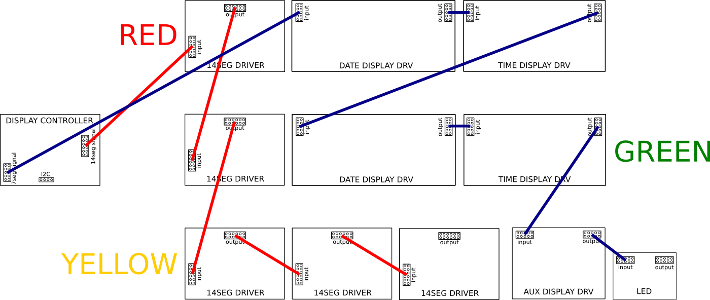
Connect driver boards with ribbon cables. 7-segment display boards and led board uses 10 wire cable, 14-segment displays use 12 wire cables.
Note that there is no 12 wire IDC plug, so I used 14 wire plug and left the last two wires unconnected on the board.
You can see the connection here:
![]()
Red wires are for 14-segment displays, blue for 7-segment displays.
-
9Step 9
Load the sketches:
- DisplayController to display-controller board
- MainController to main board
-
10Step 10
Make sure you remove the LED from pin 13 from the Arduino on the Time Circuit Main board or your keypad won't work correctly.
Back To The Future Time Circuit Clock
Back To The Future Time Circuit Clock with clock, alarm and FM radio receiver.
 Atheros
Discussions
Become a Hackaday.io Member
Create an account to leave a comment. Already have an account? Log In.