Atheros
-
It's been a while...
02/05/2015 at 19:44 • 0 commentsIt's been 9 months since last project update. I know it is long time, but I'm not abandoning this project just yet!
It's true I didn't do much work since The Sci-Fi Contest, but I hope it will change soon.
Current status
The clock generally works, but not without problems. I was working day and night to finish this project on time, so I made errors, and quite a lots of them actually...
There are 4 main issues with current electronics:
- no LED lights for AM/PM markings and the colon between hours and minutes - never managed to make that board work,
- if two loud speakers are connected at the same time to the amplifier, the main circuit won't boot and will keep resetting,
- handmade circuits, especially those on perfboards suffer from cold solder joints and other contact issues, sometimes you have to poke it a bit to start it :)
- each row of displays takes a lot of different PCBs, which require a lot of wiring make it a big mess.
Because of the above I had decided not to continue this iteration of the project.What next?
That doesn't mean it's over. I still want my cool Back to the Future clock!
Ideas for BTTF clock v2
I need to redesign what I have and I want to add some new features as doing the same thing again would simply be boring.
Redesigned electronics
The only way I can think of to fix those issues is to redesign the PCBs as follows:
- each row gets a single PCB,
- redesign and fix lots of little bugs on the main board,
- let go of THT components to fit everything on smaller PCBs
- order the PCBs, hand making them is really a pain, especially two sided...
This should cleanup most of the mess, display rows as single PCB will simplify the case design and hopefully everything will work this time.
New brain
Probably the biggest change is my idea to replace the main arduino compatible board with an Olimex iMX233-OLinuXino-MICRO running a plain linux distro. This is because of the numerous pins it breaks out, especially the audio lines. If I manage to confirm it, I can actually feed it with the sound from the FM board and output it passing through ALSA or OSS, I will be able to do lots of cool stuff, like internet radio client, play some sounds from the movie, make an alarm clock or more.
It is true this board lacks network connectivity, but that single USB port seems perfect for a small WiFi dongle!
New board design software
Currently all schematics and PCB designs are made in Eagle CAD. Unfortunately it's free and low cost versions are too restrictive in terms of board size.
The only other open source / free solution I know is KiCad. It seems quite powerful, however it's component library is really poor compared to Eagle.
The third choice I was really hoping on was the Circuit Maker as it announced by Hackaday back in September last year. The announcement made it sound awesome, all free with no limits and big company made me hope for big component library. Sadly it wasn't made available to general public since then.
In the end I started working in KiCad, but I lack motivation to continue with it. I'll wait a bit more for Circuit Maker, hopefully it will be ready someday soon.
Mecanical switches
I want to make some additional sound sources from mechanical switches of different size as feedback for user actions.
More?
Maybe a flux capacitor on the top of the case?
Next update will come when Circuit Maker is made public or I learn to love KiCad.
-
Status
04/29/2014 at 02:54 • 2 commentsSo time is up!
Here is the presentation video:
Currently working features:
- FM radio receiver
- FM frequency adjusting and editing
- setting volume
- RTC time display
- RTC time setting
- 24 7-segment characters and 20 14-segment displays
What didn't make it to the build in time:
- alarm
- RDS
- casing
- a few more buttons
RDS was really problematic. As explained in the video, I didn't manage to receive any kind of information from Si4703 Arduino library from Sparkfun. It seems it has a very limited support and unfortunatly blocking function calls (like lose keypad responsivness for 15 seconds awaiting for RDS data). I hope I'll be able to add this feature later.
Alarm and more buttons was simply a matter of time, which we run out of. Nothing difficult there, just some additional work. As for the casing, it other than little time we had, we thought it's safer to make the casing (or in this case front panels) out of wood, as it is easyer to work with. We had silver paint to pain it, but we run into lots of hardware bugs while testing all hardware connected together (first time 10 hours before this video recording). A good example is the LED connected to pin 13 of Arduino that prevented the Keypad library to work properly with the pins for the keypad we chose - so we removed it :)
There is ofcourse a lot more we would have wanted to do, but I guess we will need to leave it for later.
The contest was a lot of fun and I hope there will be more!
-
Quick Update
04/28/2014 at 17:30 • 1 commentWhat's new?
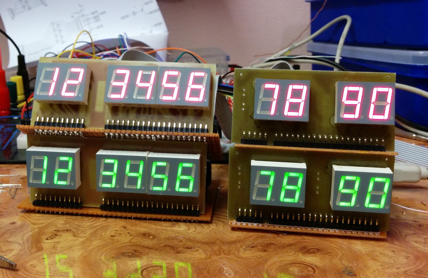
We did a lot with bwa since last update. I'm spending a lot of time working on the hardware. I decided to post some pictures.
![]()
Those are 7-segment displays for first two rows of the time circuit with the display controller board. Notice the ugly prototype boards driving the displays. It turns out those are very hard to make compared to etching normal PCBs and adding just a few jumper wires. After I made those, I decided it's time to end this prototype madness.
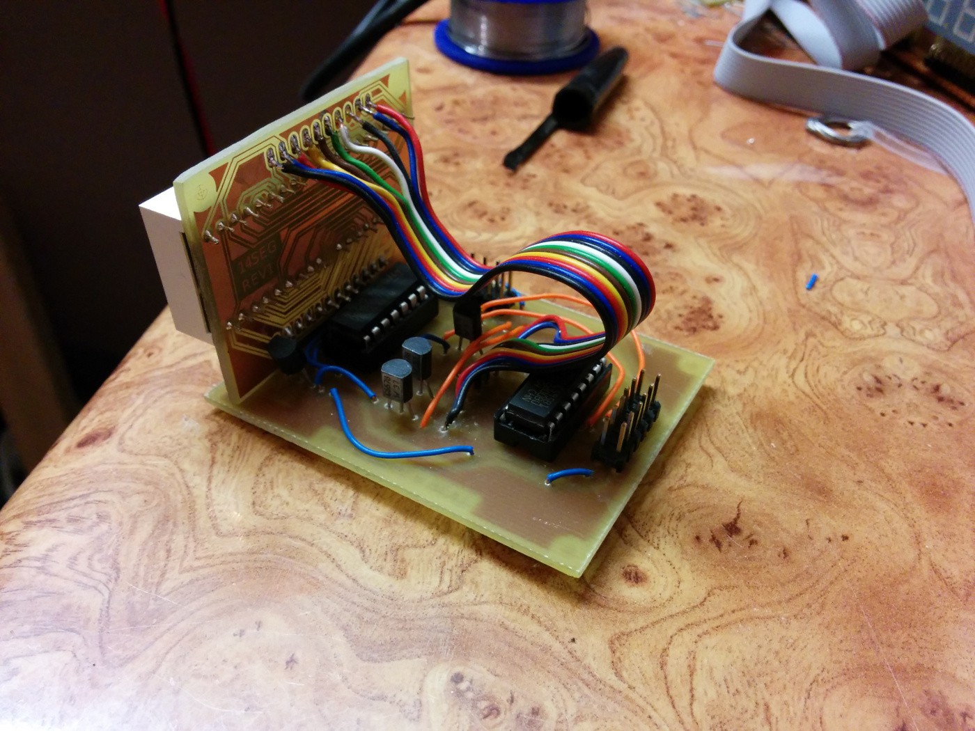
![]()
The time was running low, so it was time to speedup and make more PCBs at once. You can see on this photo 2 14-segments display boards and 3 drivers for them.
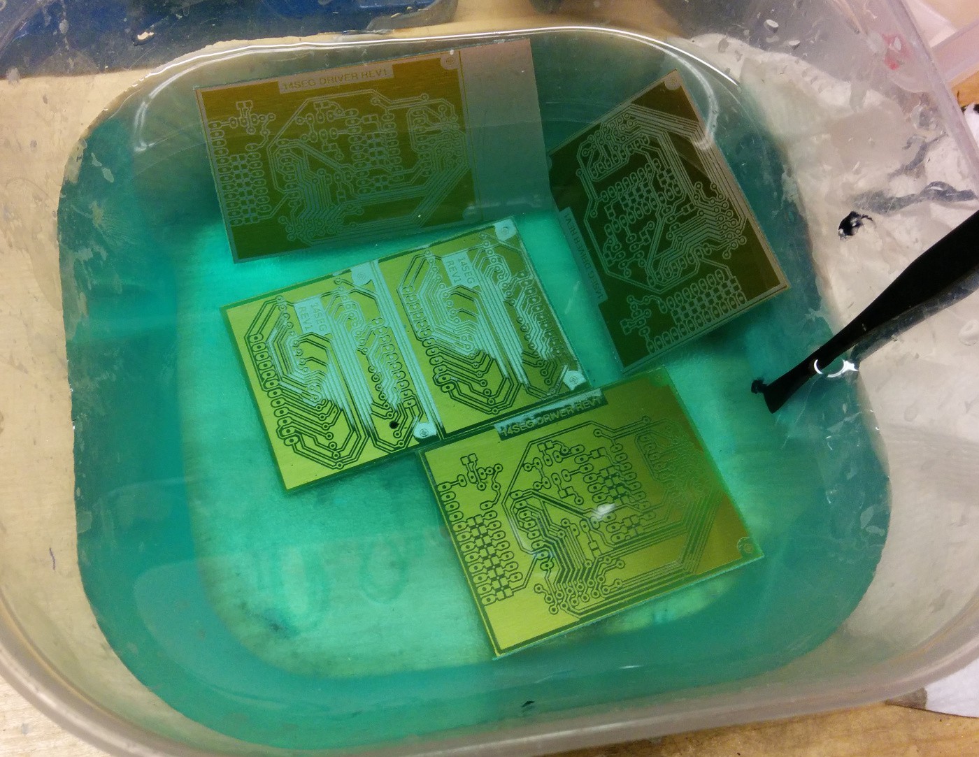
![]()
Routing lots of parallel signals on a single-sided PCB is a nightmare. We tried making double-sided PCBs, but vias and board alignment were very difficult, so all our boards are single-sided. In some eagle files, you'll see wires on top side, in the PCBs we made, they are replaced by normal wires.
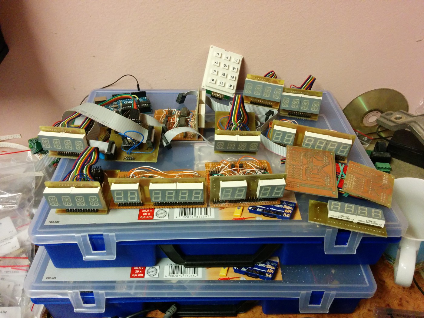
![]() Here you can see most of the PCBs we made, most assembled.
Here you can see most of the PCBs we made, most assembled.![]()
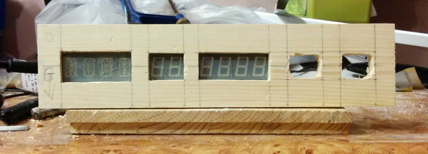
Because of time constraints, lack of tools and experience, we've decided to go with a wooden casing. This is a partially cut front panel for one of the rows.
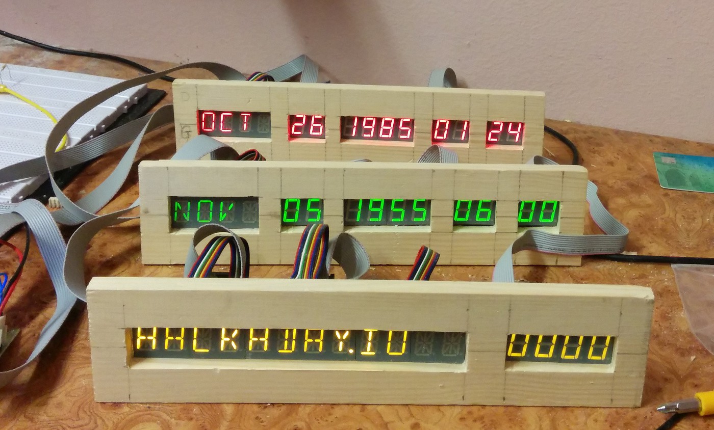
And finally:
![]()
This is how it looks. Not too bad!
The radio
I am very disappointed by the Si470x module. We failed to read any RDS from it, might be caused bad reception (I had to pull out a long write from the basement where bwa's workshop is). The main problem is when it is powering up. 9/10 it causes a loud click in the speakers and it reboots the arduino. It looks like power loss of some kind. Large power supplies and capacitors don't help. The strange thing is that it works flawlessly when there is additional power connections from my notebook. I'll have to look into it later.
Other than that, the libraries for arduino don't offer much: seek up / down, set frequency, set volume and read RDS - blocking... I have no idea how to address this issue.
What's next
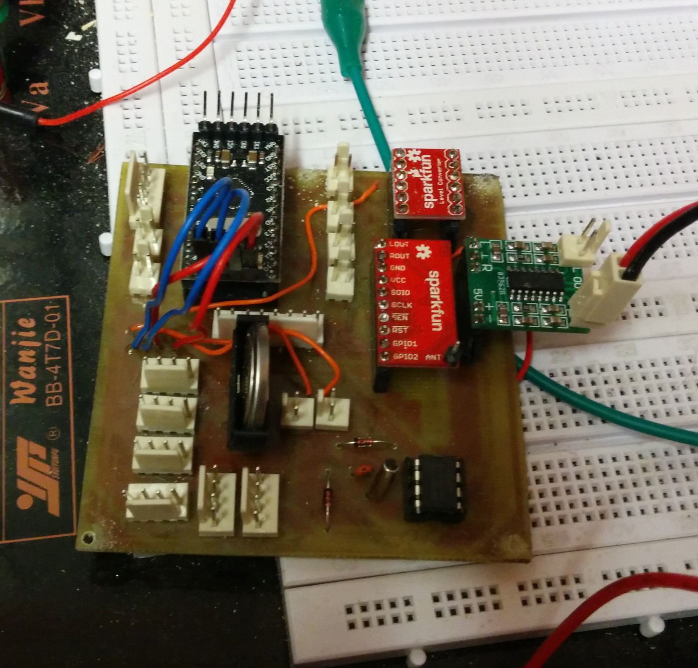
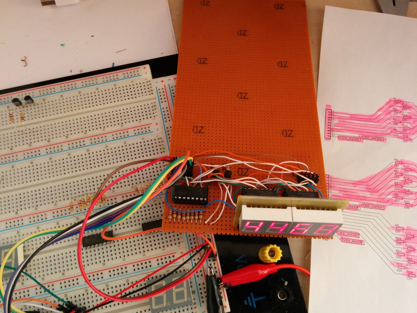
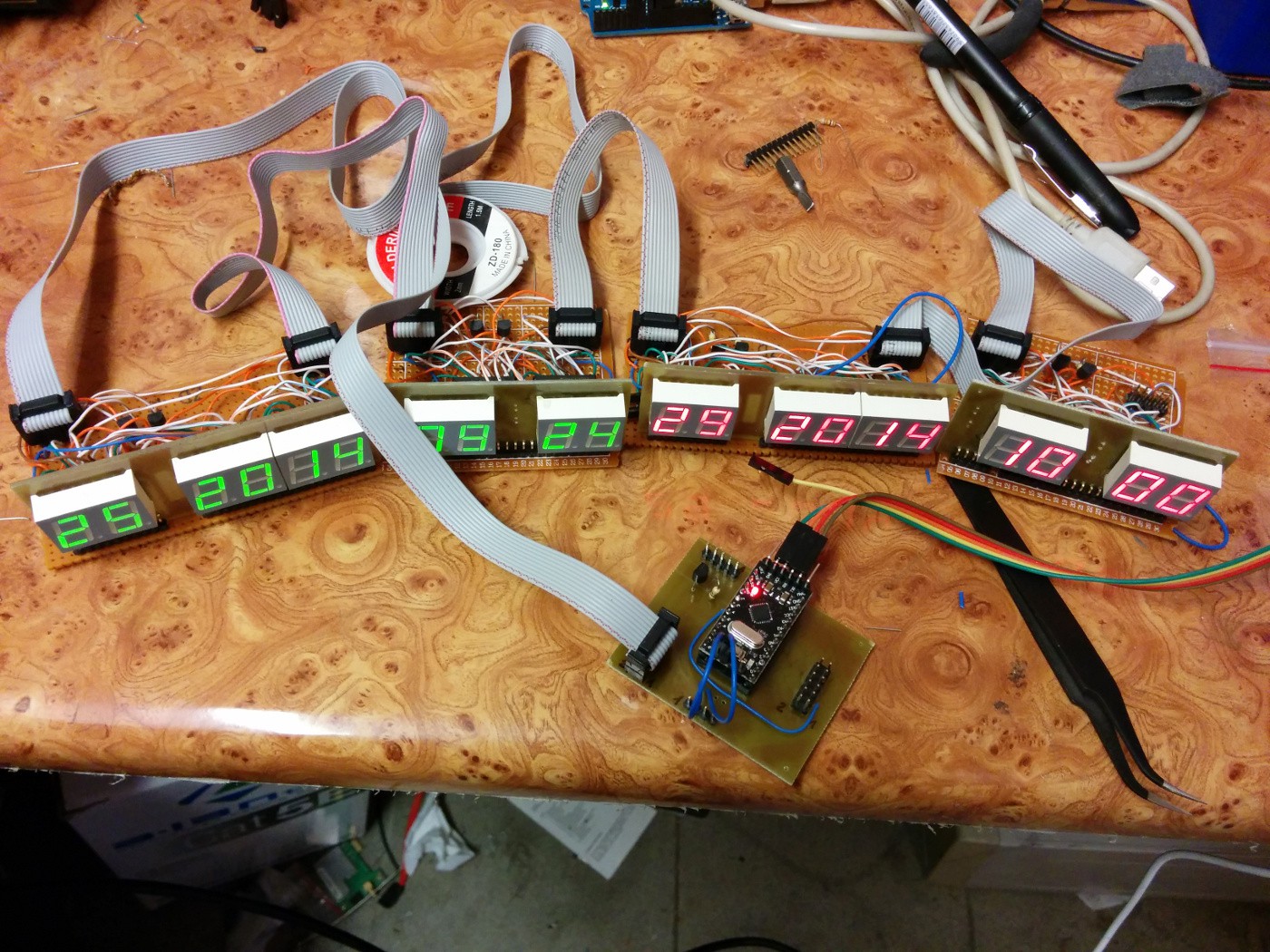
So I have most of the hardware, some untested and a beginning of the casing. I think it's time to code the Time Circuit Board:
![]()
There are chances it might work :)
-
FM radio delivery
04/24/2014 at 16:04 • 0 commentsDelivery issues
It turns out Polish Post Office is the worse courier company in Poland, and probably don't have lots of competitors in Europe. The package containing my LEDs and some other highly optional components for this project was supposed to arrive within 48 hours. The final time was 182 hours. The second package, the one holding 3 kinds of FM radio modules was still late.
The courier called me 7 days after the package was sent. Unfortunately I wasn't home. I figured it's not a big problem, I'll get it from the post office the next day. And this is where it is getting really wrong. It turns out the courier didn't leave the package at the post office as he was suppose to, instead he drove the package back to the warehouse where it will probably wait a few more days before being sent to me one more time. Needless to say chances for it reaching me before the end of the contest are unbelievably slim.
I was ready to give up, but then I decided to go through online catalogs of all electronics shops in Warsaw and it's surrounding - and I found what I was looking for! SparkFun's Si4703 FM Tuner Basic Breakout. I bought it of course so I can continue working on this project.
I learned two things:
- never trust Polish Post Office
- using rare components when you have a fixed deadline is risky at best
Now I'm wondering, what will I do with the extra 3 or 4 FM radio modules if they ever arrive...
- never trust Polish Post Office
-
Progress
04/21/2014 at 19:53 • 0 commentsWhat's new?
We were very busy this weekend - bwa was exposing and etching PCBs, I was cutting, soldering and drilling them. We've made some progress and finished most 7 segment displays:
![]()
I can chain huge number of these modules with a 10 wire cable and drive them from a single Arduino. The class that does this job just needs to know the number of characters and some pin numbers.
You can also notice the missing LEDs in time modules (empty drilled holes, plus some holes missing...). It turnes out that the service called "courier delivery 48" offered by polish post office doesn't deliver in 48h hours like the name could suggest and my package with LEDs and some other goodies sits in a warehouse not too far from me for 5 days already waiting to be delivered. It is even worse with my radio modules order. I ordered them also with polish post office delivery option, this time a service called "priority business delivery" - no idea what that even means. I'm waiting 6 days for this one and I don't event have a way to track it.
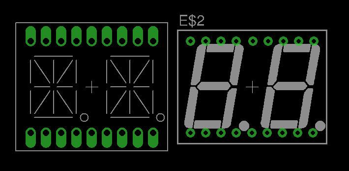
There were also different kind of problems. I was hoping we'll be able to make the display boards for month names (14 segments), but it didn't happen. 14 segment displays are not very common, so we had problems getting a component for them in Eagle CAD. The only component I found had huge pads. Those pads forced me to use thinner wires which are troublesome to etch. Here you can see the difference:
![]()
The boards have either broken wires or short circuited with adjacent wires. I don't know yet how we will handle this issue, I'm hoping bwa will be able to work this one out.
What's next?
Time is running out and there is still so much to do...
BWA will try to etch the display boards for months and I will try to design the third row of the clock, the one with huge number of alphanumeric displays (10 or 12).
I'll also try to collect the missing components and maybe figure out how to make the casing. Anyone could share some ideas? I really don't want to end up with a cardboard casing.
I'm hoping the clock will be ready hardware wise by Saturday, giving me Sunday to write the software part. This is very ambitious, but hopefully I'll manage to do that.
Wish us luck!
-
14-segments!
04/18/2014 at 19:59 • 0 commentsWhat's new?
I had to change my plans a bit and I couldn't take care of etching PCBs. Instead I took some time and looked into the 14-segment displays. I was worried at first, but it turns out once you can drive 7-segment displays, 14-segments is pretty much the same, just a few pins more:
That is almost true, except the code and font definition. I'm still working that out, but I guess it's just a matter of time.
The only other news is that I didn't receive yet the FM radio modules I ordered. By itself, it is not big problem, but I still need to make a few design decisions, and having those radio modules and testing them would answer a few questions. There is still a slim chance they will arrive tomorrow morning.
What's next?
As before, lots of PCBs to etch and now I have some practical knowledge with 14-segment displays. This will allow me to start designing PCBs for them.
Short log entry, but at least there is some progress. I hope to show more next time!
-
A bit of progress
04/17/2014 at 16:29 • 1 commentWhat's new?
I finally managed to make a new driver module for the only display board I had. I made it on a prototyping board, and somehow it works:
![]()
That board should hold 2 more characters (day of the month), however I don't have it yet. I finally feel there is some real progress - I have a component I'll use in the final clock.
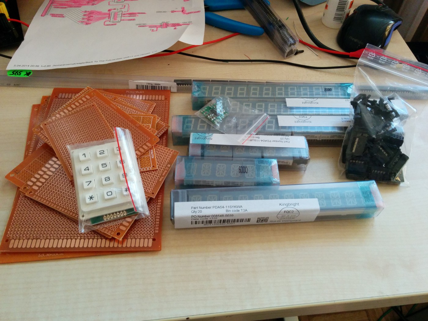
Additionally I received most of the components I'm waiting for. Here's a photo of my desk:
![]()
As you can see, lots of prototyping boards, displays, 74hc595 hiding in the back and IDC connects, a stereo audio amplifier and a nice matrix keypad. A lot of other components like resistors and atmega boards arrived earlyer. The only very important components I'm still waiting for are the radio modules. I was hoping they'll arrive yesterday, but that didn't happen obviously.
As far as I am aware, the only components I'm still missing and didn't order yet are some electric switches, an idea how to power the final device (some power plug) and speakers. I'm not mentioning the casing, as I still don't have any idea how it will be build. A lot still depending on my radio module - will it have RDS or not. If I don't get an answer by tomorrow, I'll have to consider if I want to use the lowest row as a general text display or not. I still might throw in a Raspberry Pi or some other linux powered arm/mips board I have to give it internet access, mp3 playback ability or internet radio. This would require that text display area. There is nothing decided on the subject yet. One thing is sure, I won't throw out the idea FM radio as it was in the initial specs!
I also updated the GIT repository with some more schematics and finally some source code. I've been forgetting about the code for a week now... Anyway, it's standard arduino code.
What's next?
I'll have to review all the other schematics and prepare to print and etch all the display modules for 7 segment displays. I may start making the driver modules today too.
Additionally, I have to figure out the 14 segment displays and write some code to handle it. I only know it should be similar to 7 segment displays, except I'll have to use twice as many shift registers and a lot more complicated font.
During the weekend I'll be etching the boards with my friend and hopefully have most of the electronics assembled by the end of Easter break.
I'm a bit worried time is running out, but I sill think it is possible to finish the clock in time.
-
A few PCBs later...
04/14/2014 at 19:09 • 0 commentsWhat's new?
During the week I had little time to work and no access to a workshop, so all I could do was ordering the components and planning.
I was also busy with eagle designing all the PCBs needed by this project. During the weekend, I had an occasion to etch my board designs at my brother in law's workshop (meet my teammate, BWA). While I'm still very far from having all the boards designs needed, there is some progress: I now have some basic skills at designing boards with Eagle CAD and I already learned by mistakes a few valuable lessons: manuall y dr illing small vias is very hard, at least for me reducing number of components makes your life easyer two sided PCBs are hard to make at home, specially aligning the sides with each other
Here are some photos I did of the boards I attempted to make this weekend: ![]()
This is a 4 display module and driver before I decided to use a single shift register for two 7 segment characters.
![]()
Display driver with half the number of shift registers, resistors and pins :) SMD components pads are on the other side. ![]()
And finally a working year display module. The modules I've create a GitHub repository to hold all the designs and code: https://github.com/atheros/backtothefuture-clockI'll try to keep all the schematics, board designs and code up to date there.
Bellow is a list of components and modules I need to create to finish this project.
Display module
There will be 3 or 4 display modules in each of the 3 clock rows:
- Month display
- Date display - month day and year
- Time display - AM / PM LEDs, hours, colon LEDs and minutes
There might be 4 displays in one of the rows if I decide to reuse a prototype module I already made for a year display. We'll see how much time will I have and decide then.
Display driver module
This will generally contain shift registers and will have display boards solder to them. I already worked on one of the boards, however I run into problems regarding very small vias. Right now I will try to make such module using prototyping board and through-hole components to see how small can I make it. If it will turn out well, I'll use this approach for all driver modules and the main controller board, as the only tool needed is a simple soldering iron. That would allow me to work at home and will rise my chances of completing the project before the deadline.
Display controllers
As I lack experience with electronics, I try to keep each of the modules as simple as possible, so I don't waste too much time replacing a module if I make some mistakes in them. This rises the number of PCBs and components required, but at least I can divide problems into more manageable chunks. I guess it's my software developer side, but I can't help it.
These will be driven by AVRs (arduino mini or nano?) and will control an entire row of LED displays.
Main controller
I didn't design the main controller yet, but I already have some ideas about it.
It's brain will be some arduino board. This controller will do the glue logic between input buttons, radio module, RTC and display controllers. All communication will be done through I2C.
RealTime Clock
I will use PCF8583 i2c RTC chip with a battery backed RAM. I'll use it's ram to store additional configuration, like programmed radio stations and alarm date. I don't know how this chip compares to other I2c RTCs out there, but I already used it in my previous project and I still have a bunch of unused chips on my desk (buying extra components when doing some project is a good idea!)
The realtime clock circuit will lie on the Main controller board.
Radio module
This one is a bit of a challenge. I found 3 chips with I2c interface:
TEA5767, QN8025 and SI4703. TEA5767 with small breakout modules is available everywhere I looked. It comes in very small breakout board with low pin count. I t's main problem is it doesn't support RDS/RDBS QN8025 is similar to TEA5767 with the addition of RDS. It seems however it's not available anywhere anymore. My local supplier has it in his catalog, but nothing on stock. It comes in a very similar small breakout board like TEA5767 The last chip is SI4703. It seems to be popular, but more expensive than others (3 to 4 times more expensive). It has RDS support and comes in two types of modules: breakout module and module with small amplifier for headphones. Unfortunatly, the only modules I found in Europe (aka close enough to be sure I'll get it before contest deadline) are the later ones. So I won't be able to hook them to the speakers I planned to have. This is a big problem, I should have ordered the SI4703 modules a long time ago... My plan is now to order all the module types I find and see what I can do with it. If I don't get a module with RDS support, I'll have to modify my plans regarding the last display row of my clock.
What next
I'll try to make a working display driver module. If that goes well, I'll make all the 7 segment displays and drivers this week. Then I'll work on 14 segment displays for months and RDS display.
In the mean time, I'll try to assemble all the remaining pieces of electronics I need and start thinking about the case.
I hope I still have enough time...
Whish me luck!
-
Getting started
04/08/2014 at 18:08 • 0 commentsThe idea
So, I got this idea to build a clock from Back To The Future movies. Seems pretty easy and inocent, right? Well, I though so too, until I started looking for what I need... But before that I decided to throw in some additional features, like alarm clock and FM radio. I can think of lots of additional features for this build, but I don't think I have enough time for anything more.
Things I need
Once I started to have a general idea of what I want, I started to look at the list of things I need to find. This is how it looks:
- 10x red 7 segment displays
- 10x green 7 segment displays
- 10x yellow 7 segment displays
- 3x red 14/16 segment displays
- 3x green 14/16 segment displays
- 3x yellow 14/16 segment displays
- 12 LEDs (or more)
- realtime clock
- FM radio module
- audio amplifier (mono or stereo)
- 1 or 2 loud speakers
- keypad
- some additional buttons
- potentiometer or encoder to handle volume
- lots of LED or display drivers to handle >350 individual LED lights and LED display segments
- a microcontroller or more to handle all that mess
- lots of additional electronic components (a few hundred resistors for example)
- metal case to house all the components
- lots of workshop tools
- lots of free time
- some money to buy all of the above
When I decided to start this project, I was unaware how big it is for someone unexperienced as I am, but I'll try my best.Driving the LED displays
This is the first thing I decided to take care of. A quick search provided me with what seemed to be the anwser for all my problems: MAX7219 - 7 segment LED display driver.
MAX7219
Looking deeper I found out a bit more about it.
Pros:
- drives 8 7-segment displays
- can serially chain more chips to support even more displays
- requires a single resistor to limit currentCons:
- it supports only Common Anode type displays (see Common Anode vs Common Cathode)
- it is actually quite expensive
- it isn't easy to get the original chip (see this great article)TM1638
MAX7219 was great, but I got really excited reading about TM1638 chip.
Pros:
- drives both, Common Anode and Common Cathode LED displays!
- drives 10 7-segment displays (so exactly the number I have on a single row)
- key scanner
- it is cheapCons:
- delivery from China - from 14 to 45 daysI was really excited about this chip, however the risk of it arriving after Sci-Fi contest ends forced me to choose something else.
What else is there?
There are a few more Maxim drivers, even 16-segment drivers. All difficult to get. I read about some other drivers but I don't think it's worth mentioning them here.
Other than those specialized chips, there are two other stand ways of driving LED displays: BCD to 7 segment decoder and shift registers.
BCD to 7 segment decoder
There are 7448 and 7449 chips able to take a BCD number (4 pins) and directly drive a 7-segment LED display. The idea is quite nice, however it require more IO pins than other solutions and those chips are not very common.
Shift register (the winner)
Welcome the 74595 shift register with output latches. This is the solution I chose to drive all of my displays.
Pros:
- this chip can be found everywere, even in electronics retail shops
- it is very cheap
- can chain any number of this chip driving lots of LEDs
- very easy to handle
- can drive 14 and 16-segment displays exactly the same way it drives 7-segment displays
- can drive Common Anode displaysCons:
- require a resistor for each LED segment it drives
- you either need lots of those chips or switching power to LED displays to drive an array of displays
- no standard way of connecting the LEDs to it so no standard libraryBecause I am not scared of soldering and I am a software programmer, using 74hc595 shift register seems to be the best match for me.
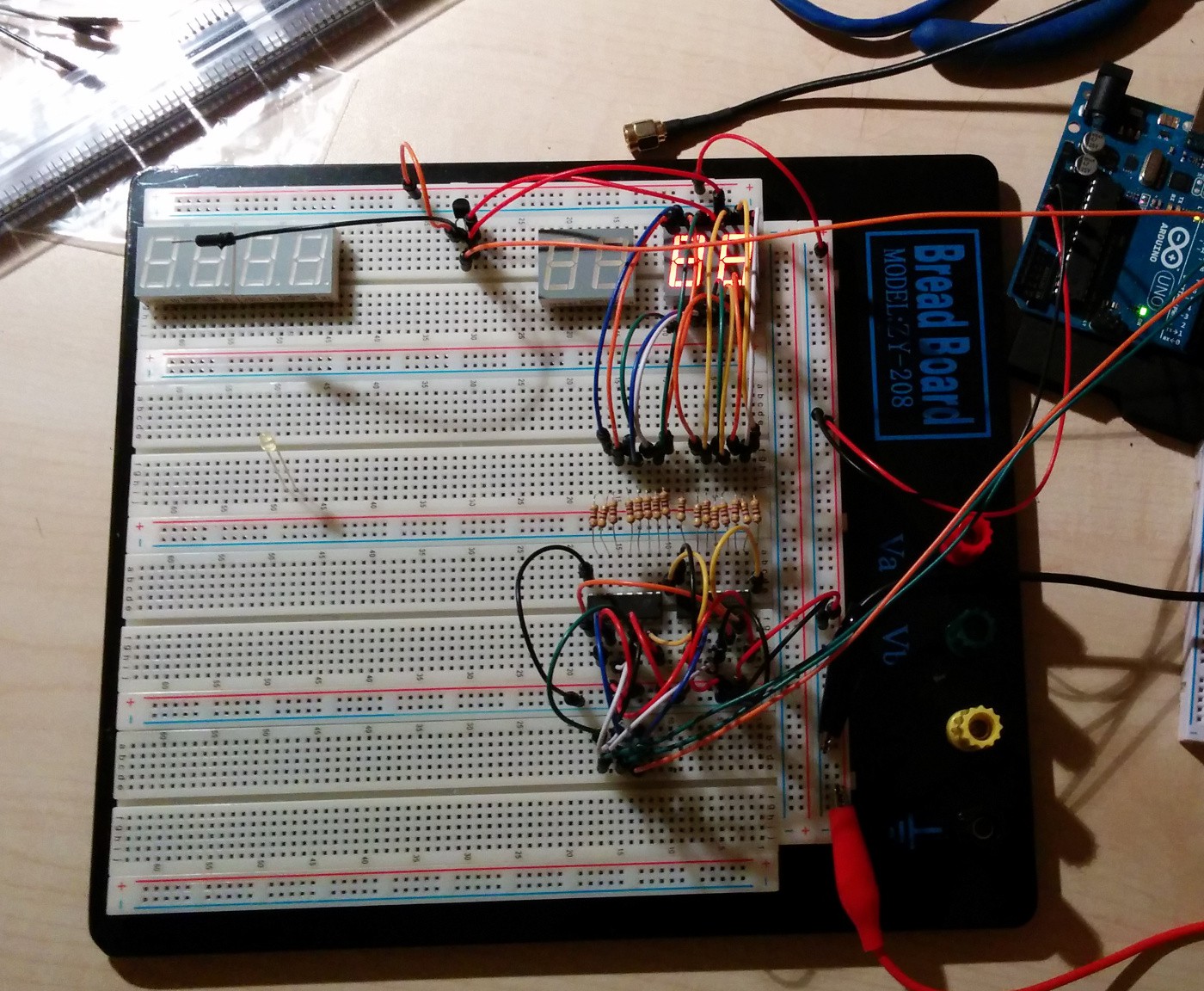
A quick breadboard wiring and a proof of concept 2 character display driven by two shift registers and an arduino shows I can do simple electronics :)
![]()
(if you notice the transistor used for PWM driving is badly connect, please ignore it...)
Common Anode vs Common Cathode
I though this question is of little importance at first, and maybe for many people and projects it is. However I found two very important differences between them:
- not all driving methods supports both types of displays
- not all types of displays are available in all colors
- not all sizes (character height) are available in all packages (single, 2 chars, 3 chars or 4 chars), colors and types...It looks like LED displays are a thing of the past. Sure, why would anyone want to mess with all those pins, additional expensive or comples drivers if there are all those cheap serial LCD displays that can display a lot more? My advice to everyone wanting to make something with LED displays, find the displays first, then worry about driving them.
Conclusion
After a week or more of research, I feel really tired. More than once I thought I have all figured out and then I had to rethink everything. But I think I made some progress.
These are the things I am certain of and hopefully won't change:
- I will be using shift registers (74hc595) to drive the LED displays
- I will be using kingbright displays with common anode (already ordered)
- 7-segment displays in dual character packages, 0.56" character height
- 14-segment displays in dual character packages, 0.54" character height (I notice the size differenace...)What next?
There is already some more progress or some failed tests if you prefere. I'll write more about it in the next update (including some photos).
Now I will be doing to the following things:
- design and build a first display board for year display (as it is the simplest one)
- build display boards for all other 7-segment displays
- build month display board (with 14-segment displays)At each step I'll try to post some progress reports, so stay tuned :)
Back To The Future Time Circuit Clock
Back To The Future Time Circuit Clock with clock, alarm and FM radio receiver.
 Here you can see most of the PCBs we made, most assembled.