Michael Skrepsky
-
Project change
01/01/2017 at 14:14 • 0 commentsI have sold the generator (with both old and new regulator), because it occupied too much space and i got bored with it. But i don't scrap the project, because i have old stationary diesel engine and i got 1kW single phase alternator without regulator, so i will change everything to suit that.
-
Mechanical/electrical construction finished
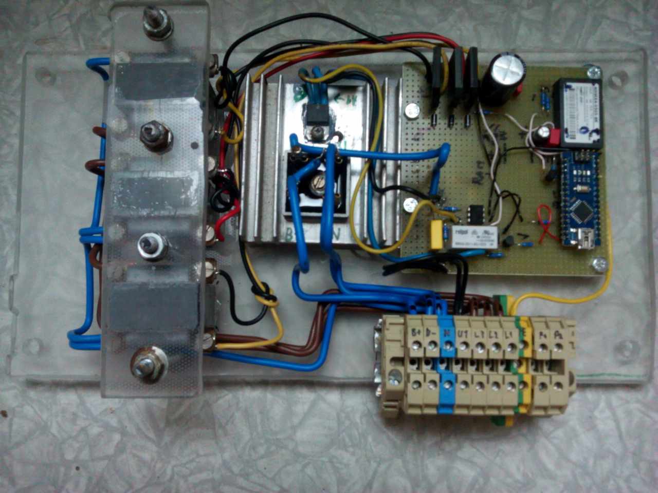
08/08/2015 at 21:28 • 0 commentsIt works!!! But it oscillates with about 1s period from 250V to 400V (phase to phase) or regulates only partially, reaching 500V. I need to make frequency compensation and protection, and replace temporary incremental algorythm with PID or something better. I will take a notebook to it and make it throw values through serial/USB. If it does not work, i would make basic ON/OFF regulation.
Relay is now switched off by software. Will update schematic after finished.
![]()
The temporary test code (that has fixed oscillation, but regulates poorly):
// experimental AC alternator voltage controller // Uses AC Control V1.1 #include <avr/io.h> #include <avr/interrupt.h> #define DETECT 2 //zero cross detect #define GATE 9 //triac gate #define PULSE 5 //trigger pulse width (counts) #define VOLTPIN A0//voltage measurement #define LEDPIN 13 int i=450; int voltage = 0; // variable to store the value coming from the sensor unsigned long oldtime; unsigned long time; void setup(){ // set up pins pinMode(DETECT, INPUT); //zero cross detect digitalWrite(DETECT, HIGH); //enable pull-up resistor pinMode(GATE, OUTPUT); //triac gate control // set up Timer1 //(see ATMEGA 328 data sheet pg 134 for more details) OCR1A = 100; //initialize the comparator TIMSK1 = 0x03; //enable comparator A and overflow interrupts TCCR1A = 0x00; //timer control registers set for TCCR1B = 0x00; //normal operation, timer disabled // set up zero crossing interrupt attachInterrupt(0,zeroCrossingInterrupt, RISING); //IRQ0 is pin 2. Call zeroCrossingInterrupt //on rising signal // initialize serial communication at many bits per second: Serial.begin(115200); } //Interrupt Service Routines void zeroCrossingInterrupt(){ //zero cross detect TCCR1B=0x04; //start timer with divide by 256 input TCNT1 = 0; //reset timer - count from zero // read the input on analog pin 0: voltage = analogRead(VOLTPIN); // synchronous voltage measurement to prevent ripple if (voltage > 640) i=i+5; // emergency voltage decrease (does not work) time = millis() - oldtime; oldtime = millis(); // period (frequency) measurement for future compensation of generator revs/min change } ISR(TIMER1_COMPA_vect){ //comparator match digitalWrite(GATE,HIGH); //set triac gate to high TCNT1 = 65536-PULSE; //trigger pulse width } ISR(TIMER1_OVF_vect){ //timer1 overflow digitalWrite(GATE,LOW); //turn off triac gate TCCR1B = 0x00; //disable timer stopd unintended triggers } void loop(){ // code if (voltage > 620) i=i+1; // decrease phase if (voltage < 580) i=i-1; // increase phase if (i > 600) i = 600; //limit if (i < 300) i = 300; //limit //i--; OCR1A = i; //set the compare register phase desired. //if (i<300){i=550;} delay(20); // print out the value you read: Serial.print(time); // write period of AC Serial.print(" "); Serial.print(i); // write phase Serial.print(" "); //Serial.println((10*voltage)/205); // 10*voltage in volts Serial.println(voltage); // voltage in ADC units - / 1024 * 5 } -
baseplate
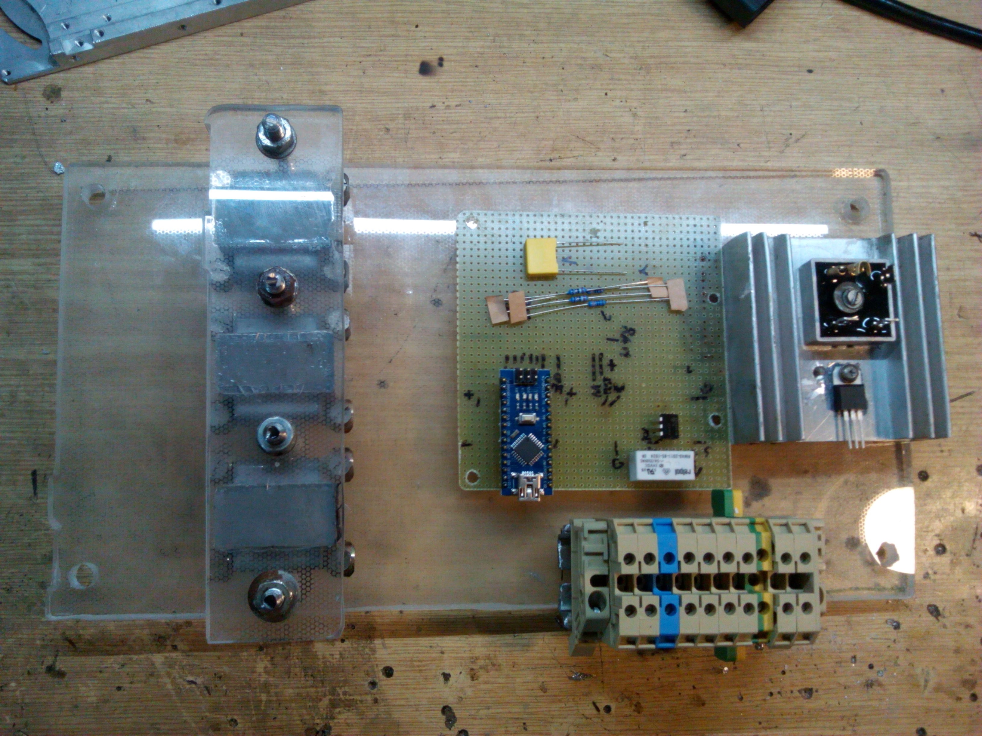
08/06/2015 at 21:03 • 0 comments![]()
baseplate completed, voltage transformers and connector installed.
Automatic Voltage Regulator for AC alternator
Can be used to replace old AVR regulator for AC 3 phase alternator.