Adam Munich
-
November 2014 - Designing a prototype source pt. 3
08/15/2015 at 06:02 • 0 commentsAround the end of October, I finished up the design of all the plastic components which would house the electronics of a 200W x-ray system. It was now time to design those electronics!
Back in September, I had an idea of how I should go about doing this. The system would have to have, among other things,
- A means of charging lithium ion batteries
- A means of monitoring and protecting those batteries
- A user interface
- A radio for remote operation
- A boost converter capable of 300W pulses
- An H bridge
- A power transformer
- A voltage multiplier
- A voltage source for the cathode
- Safety features!
After careful re-evaluation of my older schematic, I deemed it unsuitable for the job at hand. Particularly, because it would take "too much tweaking" to get operating reliably, given that, the STM32 would be doing almost all of the work. This might seem counter-intuitive to some, but the job just felt simpler to do with op amps instead.
Revision 1: "Hey this could work"
Over the course of a week, I chose low-cost parts and tossed them onto the board, in a way that felt like they'd work without much incident. Like most of my projects, I didn't bother drawing a schematic, and instead just went with the signal flow, so to speak.
The analog electronics are all done with stand-alone parts, and, to synchronize everything and provide a UI, I chose to use a Teensy 3.1 for this prototype. I did so, to allow me to use the fantastic OpenGLCD library, and save me the effort of writing a frame-buffer and object-oriented menu structure.
I managed to get it all done on a 2 layer PCB :-).
![]()
![]()
![]()
![]()
-
After receiving a copy of this board from Bay Area Circuits, I promptly put it together, only to discover that... it mostly worked! There were a few bugs however, and those were;
- Far too much switch bounce for the UI buttons, which are fed though a 7-3 multiplexer before entering the controller. Software filtering proved to be incapable of handling this.
- An unreliable cathode heater power supply, which would fail to start up on occasion due to the nonlinear resistance of a cold -> hot cathode transition.
- Issues with what proved to be a rather useless coulomb counter.
- A few noise issues here and there.
-
![]()
-
Board 2 solved these issues by adding filtering, better ground structures, an improved cathode power supply, and an IO expander to allow for some finer control of the analog beasts scattered about.
I also added a NAND gate, which hard-resets the PCB by pressing two buttons simultaneously on the machine.
-
![]()
-
However, it was not without its own problems.
- The coulomb counter still couldn't make sense of the noise while charging.
- The LCD panel sometimes would get strange white pixels in random places.
- The x-ray machine could fail in such a way that the beam could get stuck on.
I found the latter out the hard way, and had to cut wires next to a live x-ray tube (how fun).
Evidently, if the main micro-controller freezes, it's possible for pins to get stuck in certain configurations that ensure the power electronics are still operational, which. is. bad.
-
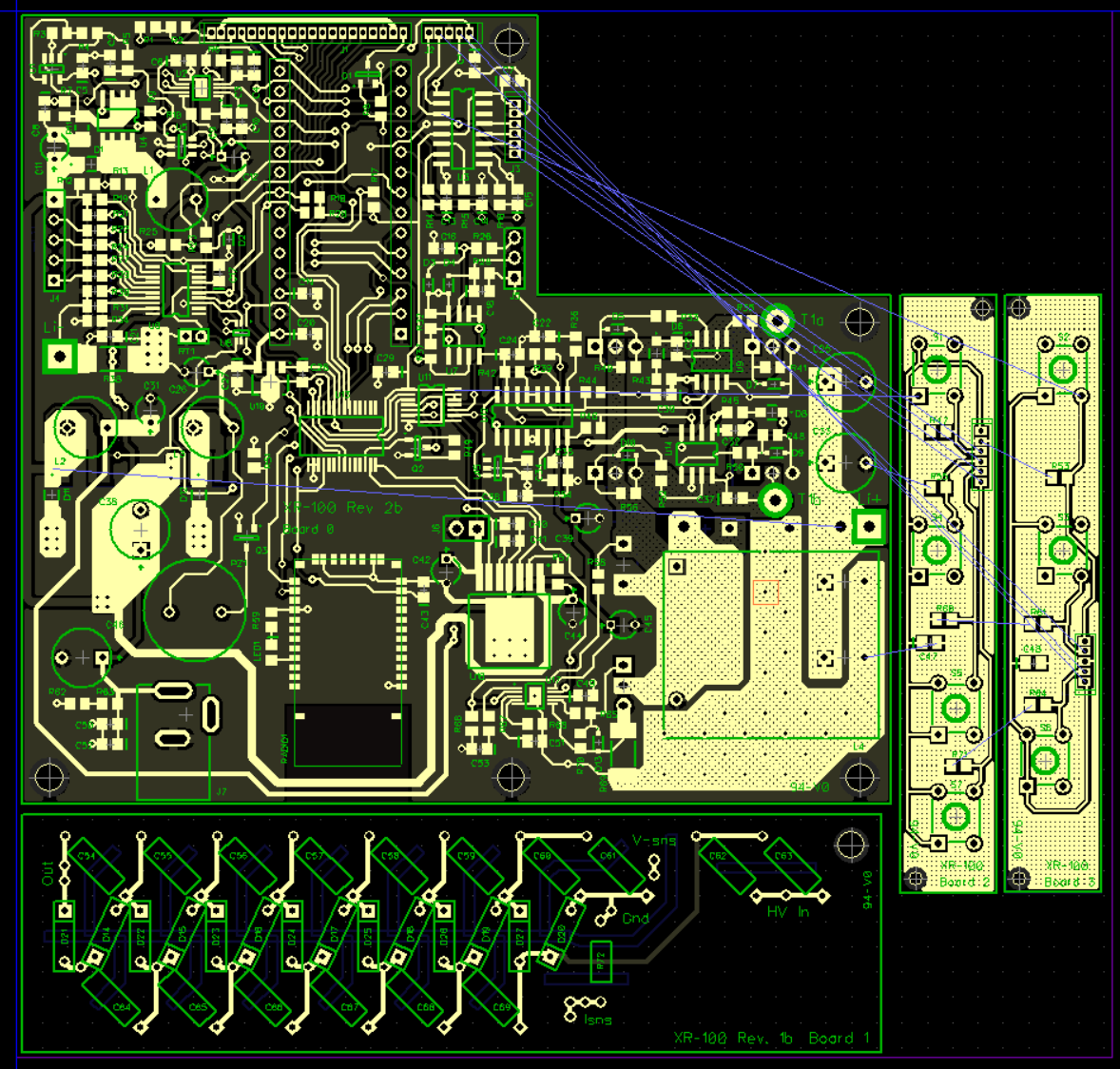
Board 3 solved these issues with a watch-doge timer, 3.3 to 5V buffers for the LCD panel, and a completely scrapped coulomb counter.
I added a fuse as well, after another incident caught everything on my board, but the bluetooth radio on fire. The radio simply got hot enough to melt itself off the pads, but curiously, still worked afterwards.
![]()
-
But alas, there was one more problem, and a rather obscure one too.
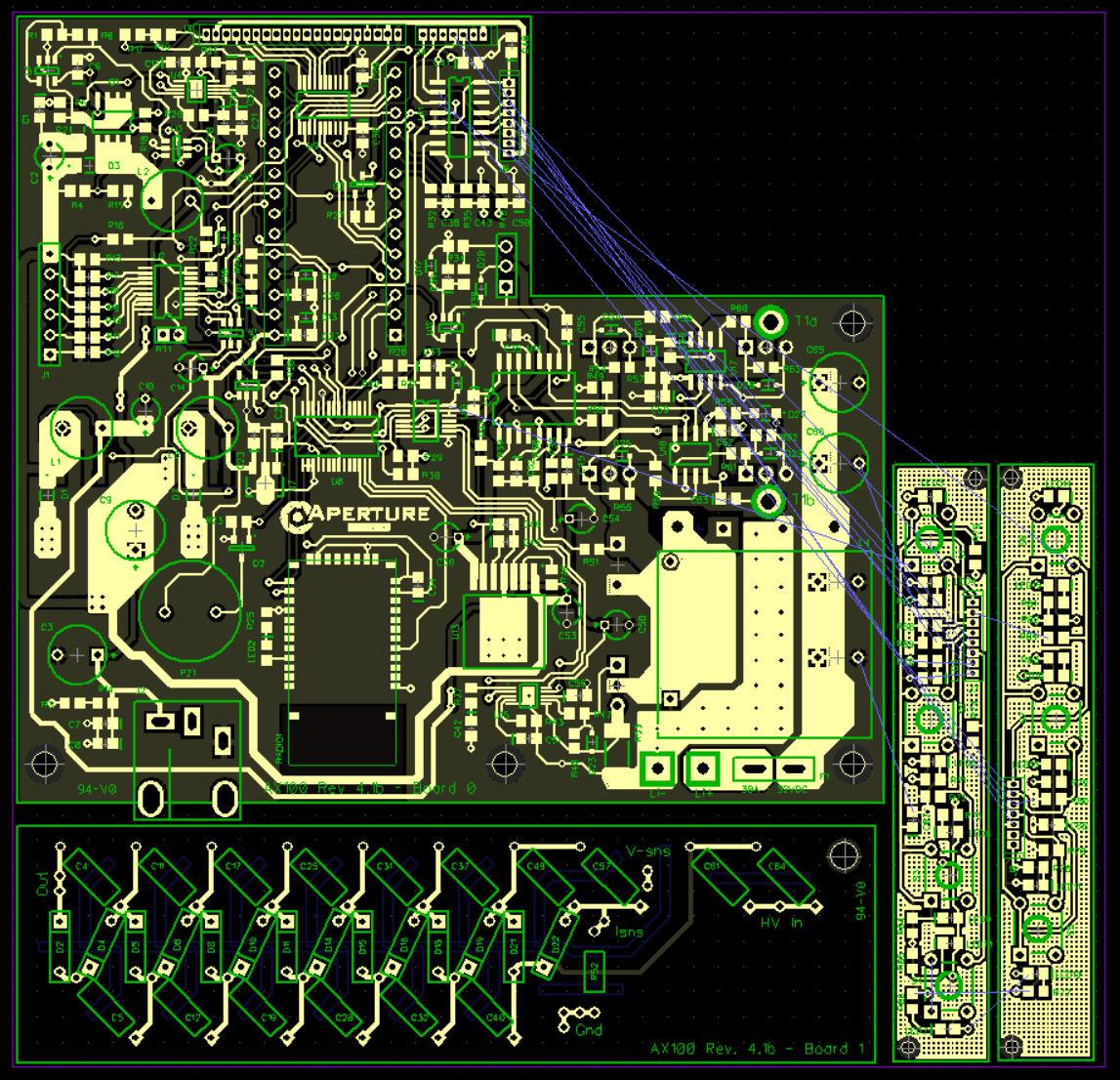
To generate my PWM train for the H bridge, I used a rather old IC, which had a duty cycle limitation of 45%. I didn't expect this to be much of a problem, but, to my dismay, the inability to switch at 50% duty cycle allowed for spurious oscillations to happen during portions of the x-ray burst. To fix this, I swapped the UC3524 IC for a more modern PWM controller.
And added LEDs to the buttons because reasons.
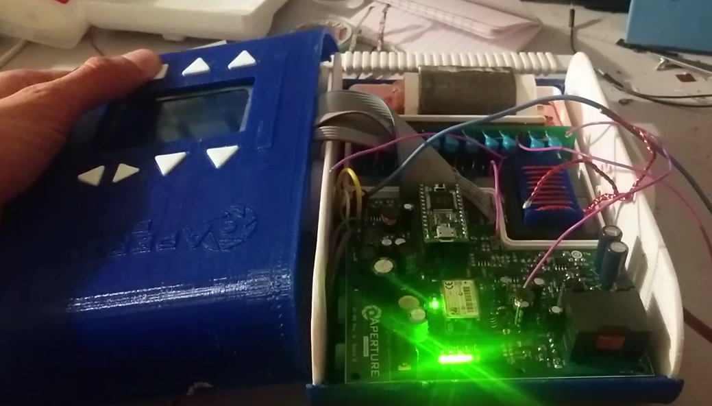
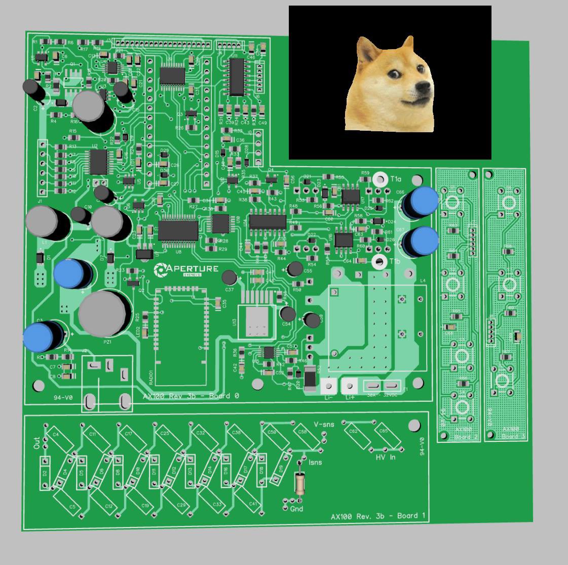
![]()
The 4th time was the charm :-)
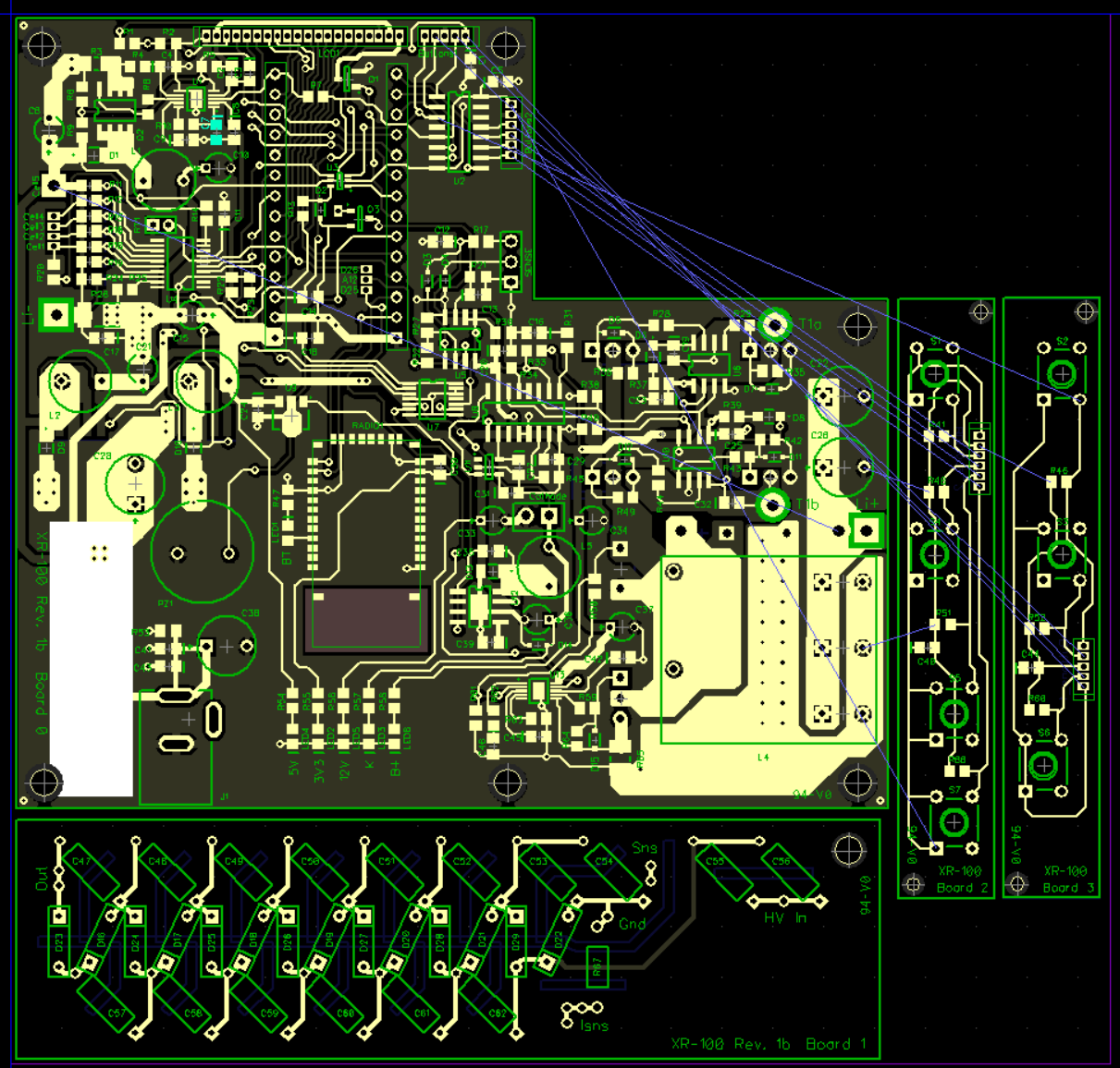
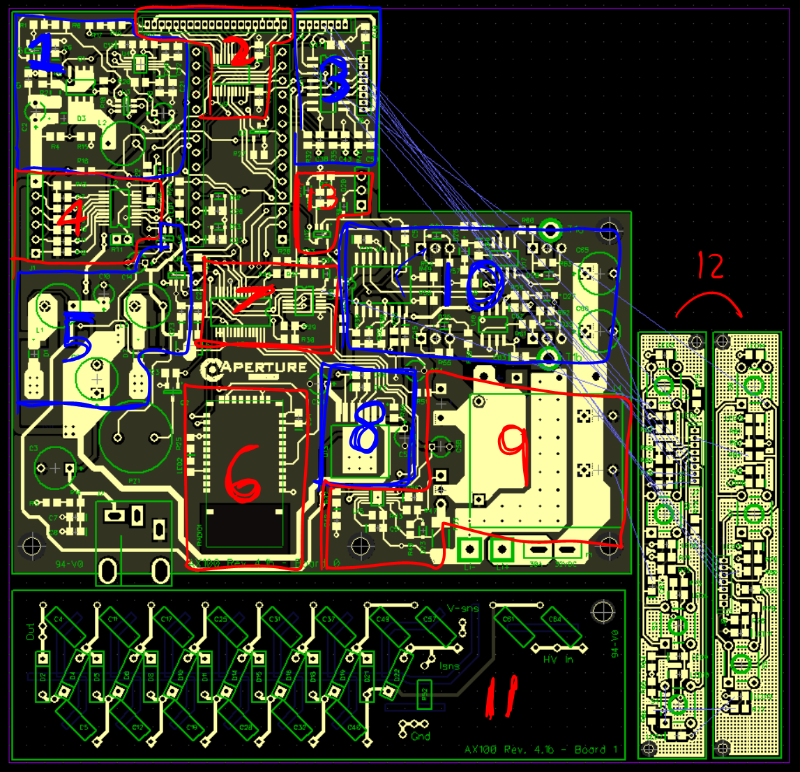
So, what's on the board?
![]()
In no particular order...
- A current mode, or voltage mode (selectable) boost converter for charging the lithium batteries.
- Buffers for driving the LCD panel, and an LED driver for the backlight.
- UI button filters and multiplexer
- Battery management DAQ and analog switch
- Power rails, watchdog and standby power circuitry
- Bluetooth radio
- IO things to control the power electronics
- A buck converter for the tube's cathode
- A giant boost converter for the H bridge
- The few-hundred-watt H bridge
- A voltage multiplier
- Buttons and LEDs
- Feedback filtering to monitor the HV power supply
Board files:
https://drive.google.com/file/d/0BwIWrZZX8IW6U2trR2JNYU9ZRzA/view?usp=sharing
Parts list:
![]()
Have fun!
-
October 2014 - Designing a prototype source pt. 2
08/15/2015 at 05:17 • 0 commentsTo house all the electronics, I needed a plastic shell. Actually, several plastic shells; one for the high voltage oil tank, one to hold an x-ray tube, one to hold aluminum filters, one to hold the high voltage oil tank, a handle to hold everything... it goes on!
To design these, I broke out my favorite CAD suite: Autodesk Inventor. I also broke out the caffeine, and spent some 14 days staring into inventor, to design the following *injection moldable :D* parts
-
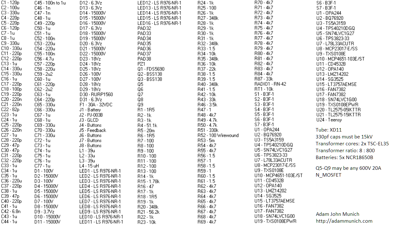
A model of my chosen x-ray tube:
![]()
-
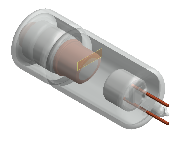
A shell to hold the tube, and a lead jacket around it:
![]()
-
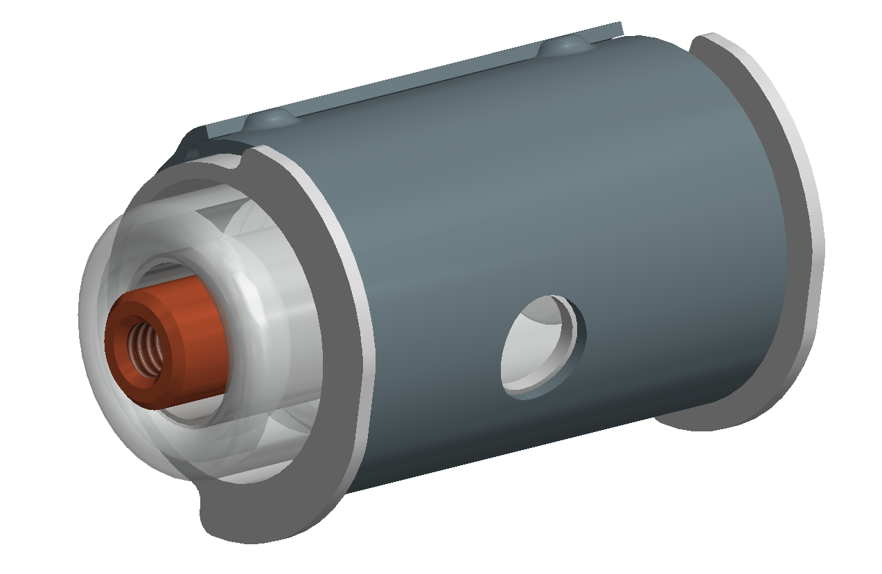
An oil tank, to hold the tube, the shell, and its wrapping:
![]()
-
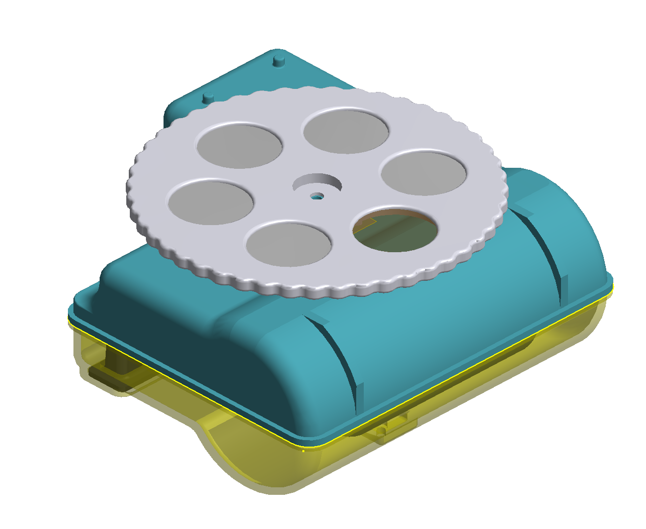
A lid for the oil tank, and a rubber chamber to allow for thermal expansion:
![]()
-
Aluminum filters of different thicknesses, and a disk to hold them in place:
![]()
-
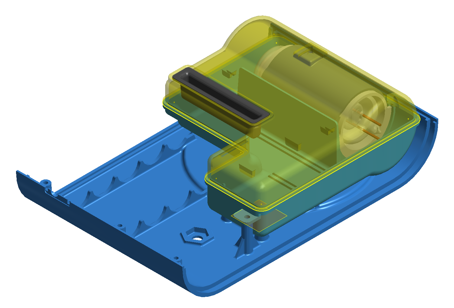
A shell to hold the oil tank, and other parts:
![]()
-
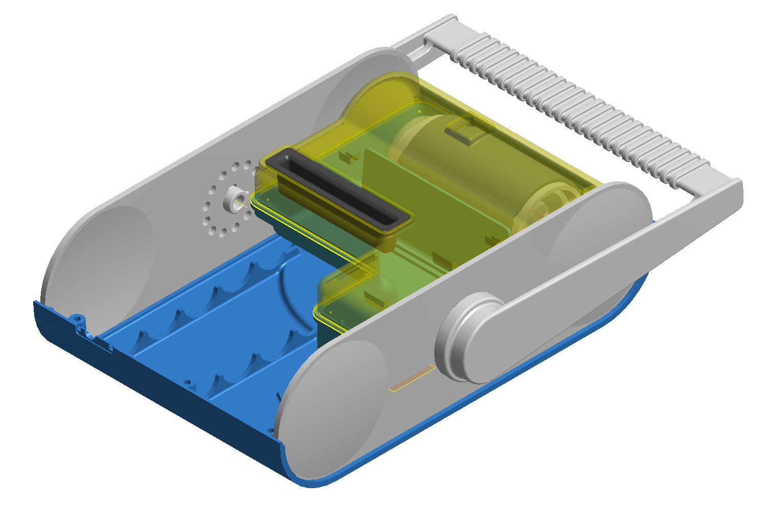
Sides, and a handle to allow for easy carrying.
![]()
-
An LCD, and PCBs to hold components, buttons, and the voltage multiplier:
![]()
-
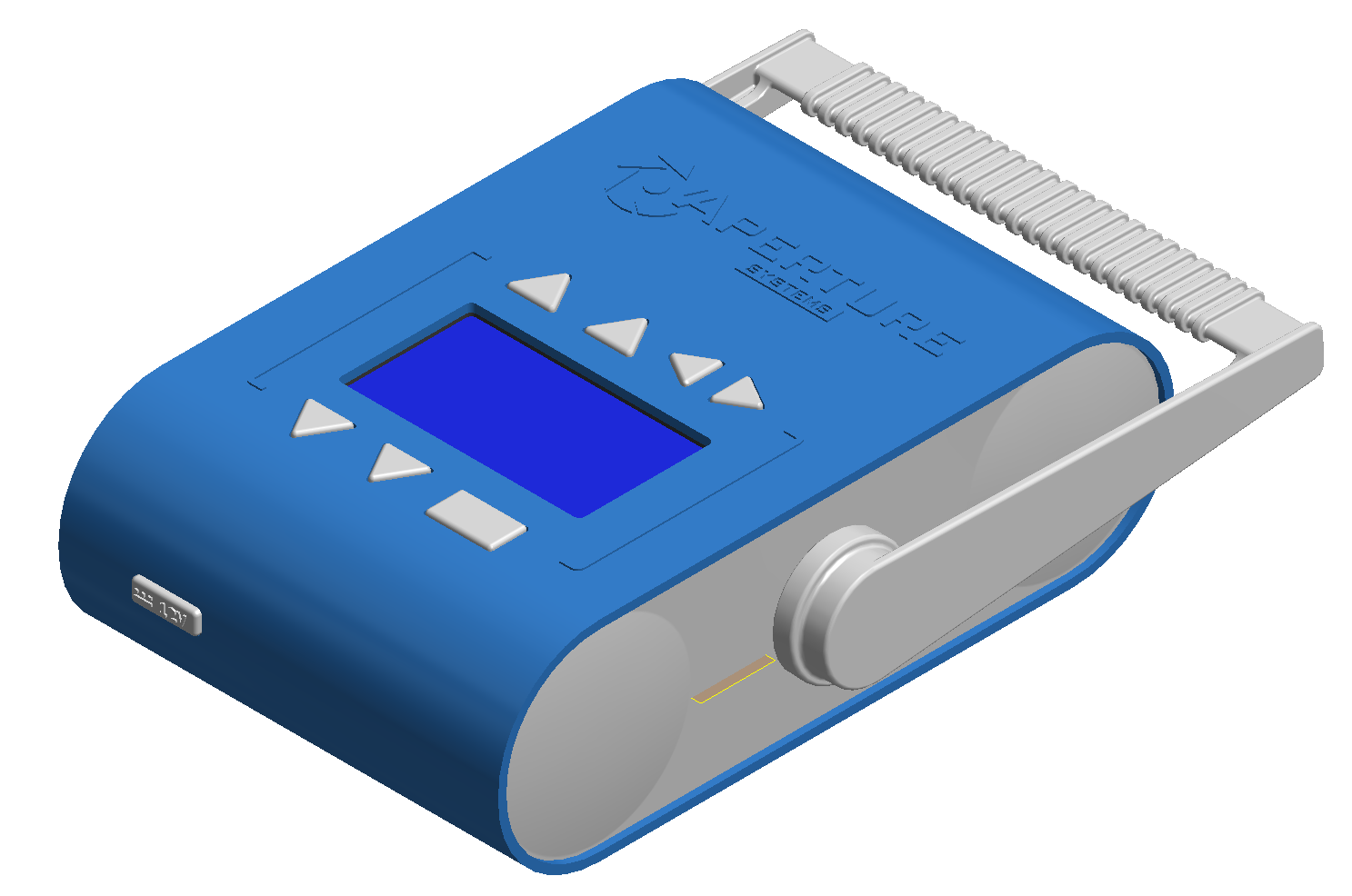
And finally, a top shell and a rubber flippity-flap to cover the power receptacle:
![]()
______ _ ______ _ | ___ \ | | | ___ (_) | |_/ / __ _ __| | __ _ | |_/ /_ _ __ __ _ | ___ \/ _` |/ _` |/ _` | | ___ \ | '_ \ / _` | | |_/ / (_| | (_| | (_| | | |_/ / | | | | (_| | \____/ \__,_|\__,_|\__,_| \____/|_|_| |_|\__, | __/ | |___/![]()
Then came the 3D printing, the long, torturous 3D printing.
![]()
Some people have trouble with parts peeling off, but often, I have the exact opposite problem. x_x
-
September 2014 - Designing a prototype source pt. 1
08/15/2015 at 04:45 • 0 commentsAt this point, I wasn't feeling too hot. After 2 months of straight "no's", something clearly had to change if I wanted to achieve my long-term goal of bringing medical x-ray imaging to everyone. I felt that I needed something more convincing to win people over, a prototype of sorts.
Now, to assume that I could design the product I described with the resources I had at the time (a hackerspace, myself, some cad programs) would have been foolish.
So, I set a lower bar for my prototype model: a 200W, backpack x-ray source.
![]()
I set a goal to have this designed by December.
To do so, I worked 14 hours a day, every day, for 3 months, until this was done. I let family and friends fall off my priority list, and eventually became very, very depressed, yet still kept on working anyway. In retrospect, this was a terrible decision.
September was a month of systems design. Particularly, planning out how I could design such a 200W source with a minimum number of parts, and a maximized ratio of off-the-shelf components. After 3 days, I had something that looked like it could work.
![]()
The system contains as few parts as practical, to provide;
- Lithium ion battery charging.
- Lithium ion battery management.
- Battery safety.
- Closed loop high voltage inverter control.
- Closed loop cathode control.
- Remote control.
- Power management for all parts.
Which in summation, would be enough to build a 200W x-ray system.
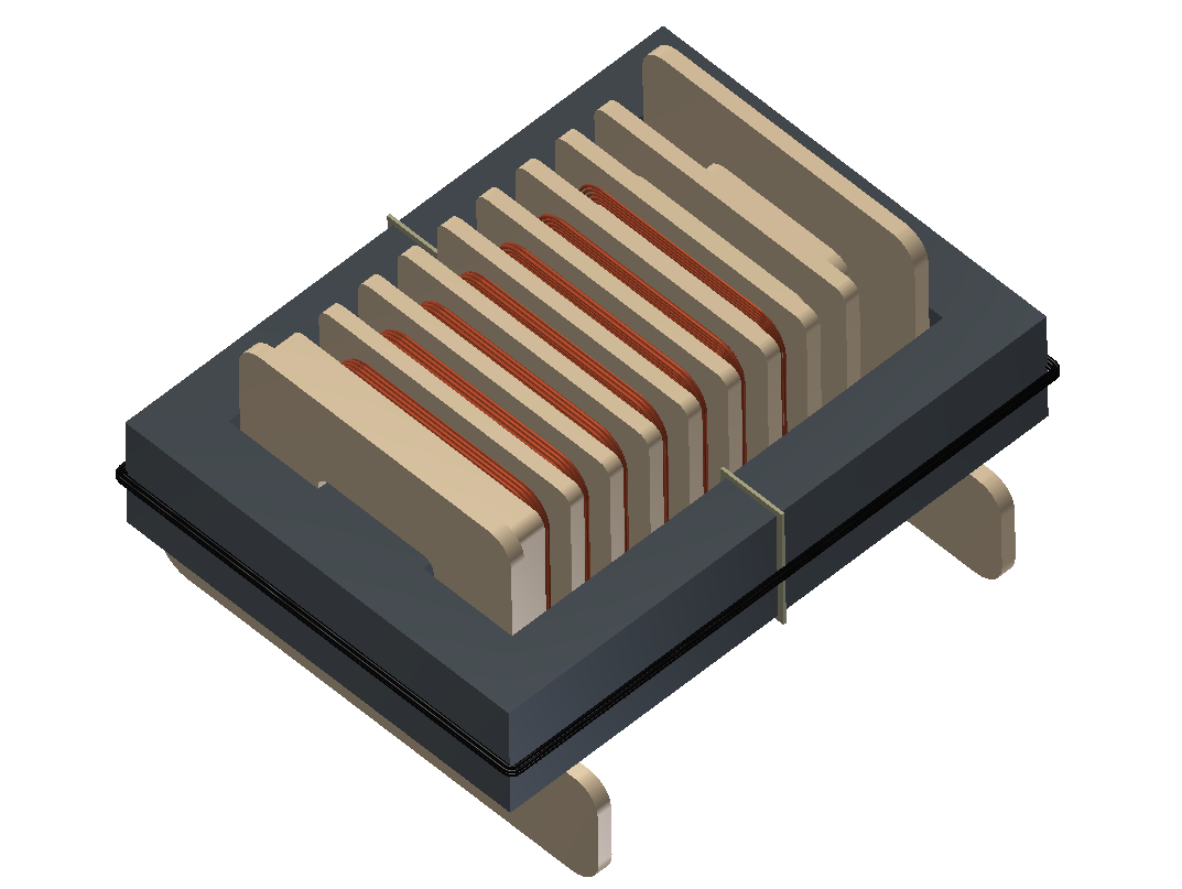
I decided at this point, that I should probably design my own transformer for the machine. There didn't seem to be any good ones readily available, so, I chose a core from TSC ferrite international that seemed large enough (based on past experience) to handle 200W swimmingly.
When designing a high voltage transformer, it's important to make sure you can get the highest winding ratio practical, without saturating the transformer's core due to too much flux. This is so, because at high frequencies capacitive losses matter a lot, and to ensure that all of your energy isn't trickled away, you use as few turns as possible.
![]()
I chose 8 turns, to 800 for a 1:10 ratio. Given the core's cross sectional area and material, I was limited to a saturation flux of about 200mT, which worked out to about 30 amperes into the primary coil, with a sizable safety margin.
It's worth noting that, to accommodate so many windings you must break the transformer bobbin up into sectors, each with sizable insulation from other parts of the transformer. Failing to do this will ensure dielectric breakdown of your wire!
For those of you who haven't learned transformer design, there is a nice video available to brush up on your core competencies :-)
-
July, August 2014 - Months of rejection in San Francisco
08/15/2015 at 03:53 • 0 commentsDuring this month, I sought out, and spoke with potential investors for my x-ray project. At the time I figured, "oh boy, this will be easy! We're doing real science, not building dog walking apps".
Most of these meetings went something like this;
- We'd be happy to meet with you!"
- --- We meet, and explain the project)
- "Sounds great! How many customers or users do you have?"
- --- I say zero, and explain it will take a few years to develop a product like this.
- "Oh. Well, do you have a prototype"
- --- I explain, no, but I have schematics and have built things like this in the past.
- "That's exciting. Please keep us informed"
It took some time to realize that "please keep us informed" is actually a "no".
After many more meetings like this, I started to get the impression that no one really cares if you have an invention.
Further,
People love to say things that make you feel good, but mislead you, and often cause more harm than if they had just been direct.
Further still,
People are very quick to make short term decisions, and very bad at understanding benefit in long-term thinking.
And further still,
When you're 20, it's hard to be taken seriously.
I had teammates abandon me at this point, their faith lost in my ability to lead this project.
Suffice it to say, at the end of august I wasn't in the best of spirits.
![]()
-
June 2014 - A month of invention
08/15/2015 at 03:30 • 0 commentsI crashed at a friend's place when I arrived in California, and, set up a messy workshop in their garage.
At this point, I had tossed away my old life, my university studies, in a choice that would make some people's parents disown them. But, what is success, if you don't first give yourself an opportunity to fail greatly?
![]()
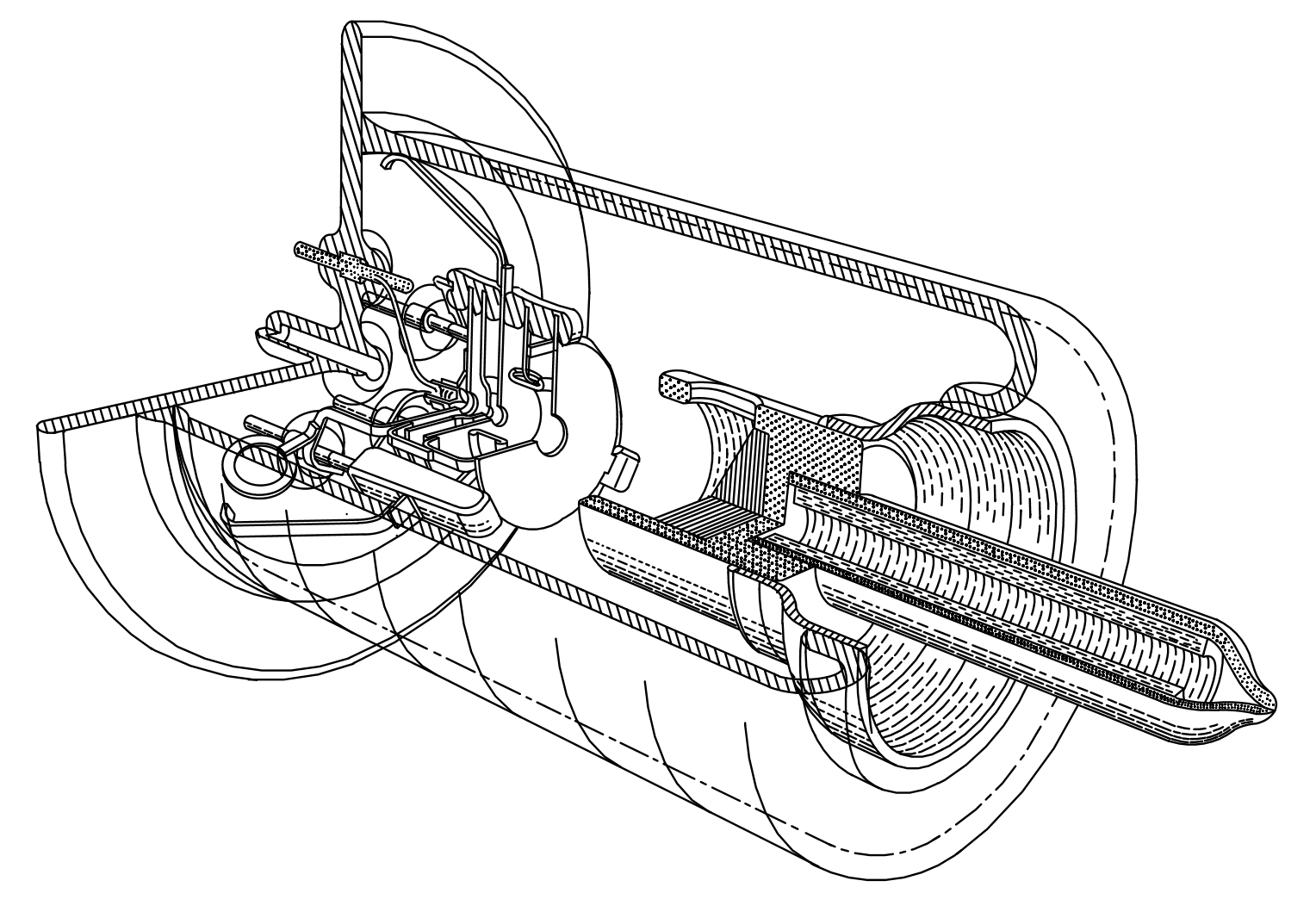
Here, I worked diligently for a month. In order to ensure that this x-ray source would be low cost, and provide the extreme powers needed for sharp radiographs of living objects, I had to redesign the x-ray tube such that I could take high resolution photographs without any moving parts inside.
To do so, I added electron optics to the tube, designed in such a way that I could have variable control over the x-rays' convergence, and gate the electron flow to allow for pulsed beams of x-rays to be emitted.
![]()
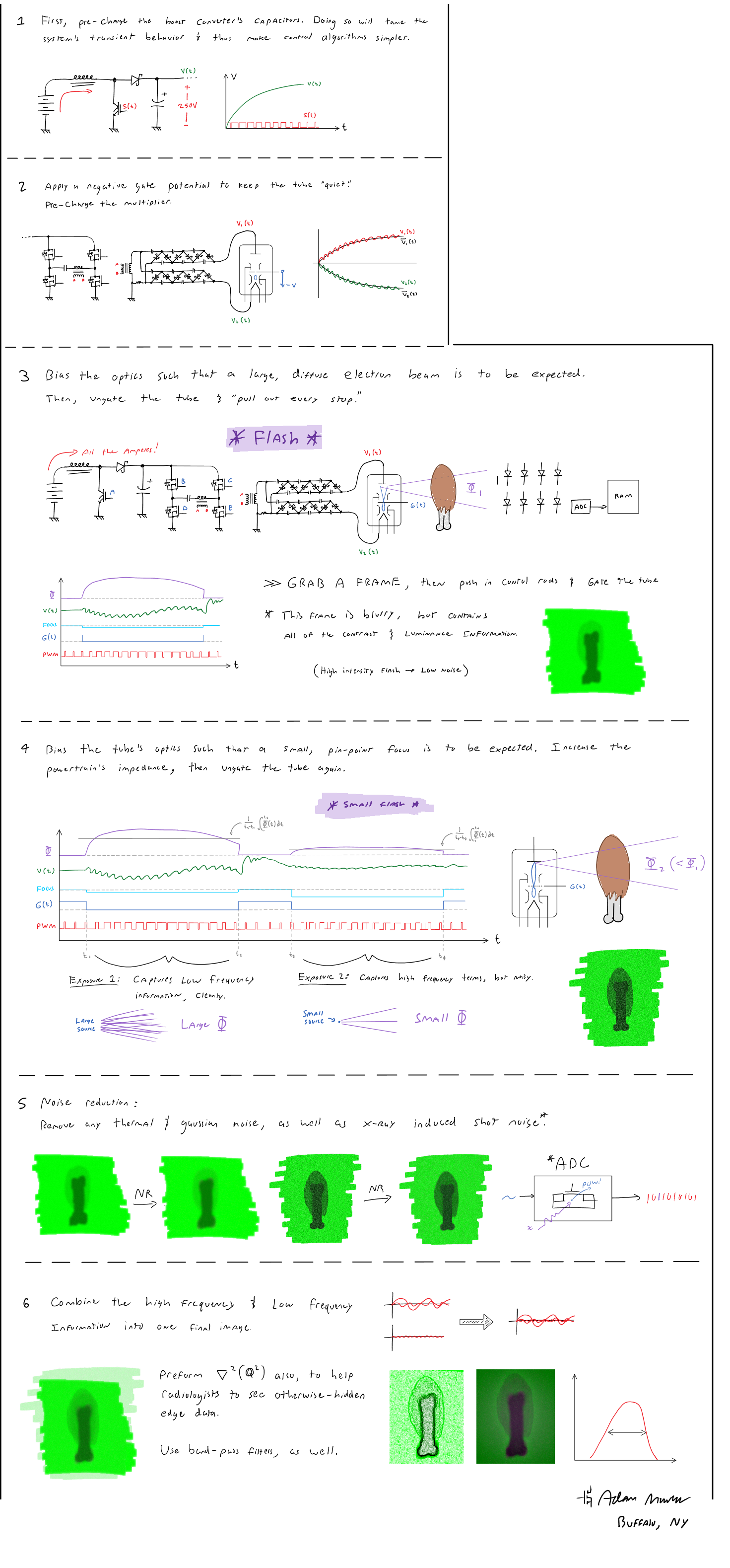
Which, would allow me to take bright x-ray exposures in the following manner, using some simple Fourier mathematics:
![]()
After spending nearly 2 weeks reading everything USPTO.gov had to offer, I learned all that was necessary to write a patent, and filed one for this work. Personally, I hate patents, and believe the system is very broken.
Unfortunately however, it people still require them, if you're to be taken seriously.
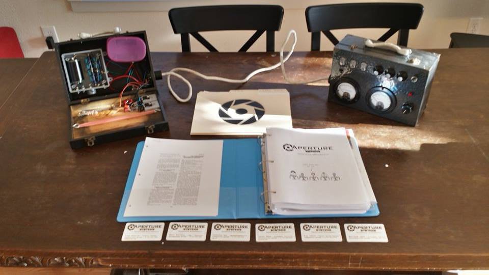
Following this, I convinced a few friends to tag along in this journey, put together a business proposal,
![]()
... and hit the road again.
-
May 2014 - Writing a detailed technical proposal and tossing away my old life
08/14/2015 at 21:10 • 0 commentst the end of March, (and early april), I was under the impression that I had failed to build a convincing case that it's possible to design a low-cost mobile x-ray system capable of being used for human diagnostics.
At the time, it appeared further research was needed to build a more convincing argument.
So, being a university student at the time, what seemed like an acceptable option was to write a "thesis" of sorts, with a problem statement, research, and detailed designs of some x-ray system components which would be integrated in such a machine. For kicks, I decided to illustrate much of this document, such that it wouldn't be a boring read.
For about a month I worked all night on this, and at the end of may, had something quite detailed, with many illustrations.
![]()
For reasons of bandwidth, I can't host the 400Mb file for y'all.
However, here are some fantastic tidbits that are worth sharing!
  _   _                 _
 | | | | _____      __ | |_ ___   __  __     _ __ __ _ _   _
 | |_| |/ _ \ \ /\ / / | __/ _ \  \ \/ /____| '__/ _` | | | |
 |  _  | (_) \ V  V /  | || (_) |  >  <_____| | | (_| | |_| |
 |_| |_|\___/ \_/\_/    \__\___/  /_/\_\    |_|  \__,_|\__, |
                                                       |___/
Below is a comic that describes how a project such as this x-ray source would proceed. To some, who have many engineering projects under their belt they may find it a bit humorous (and too true).
-
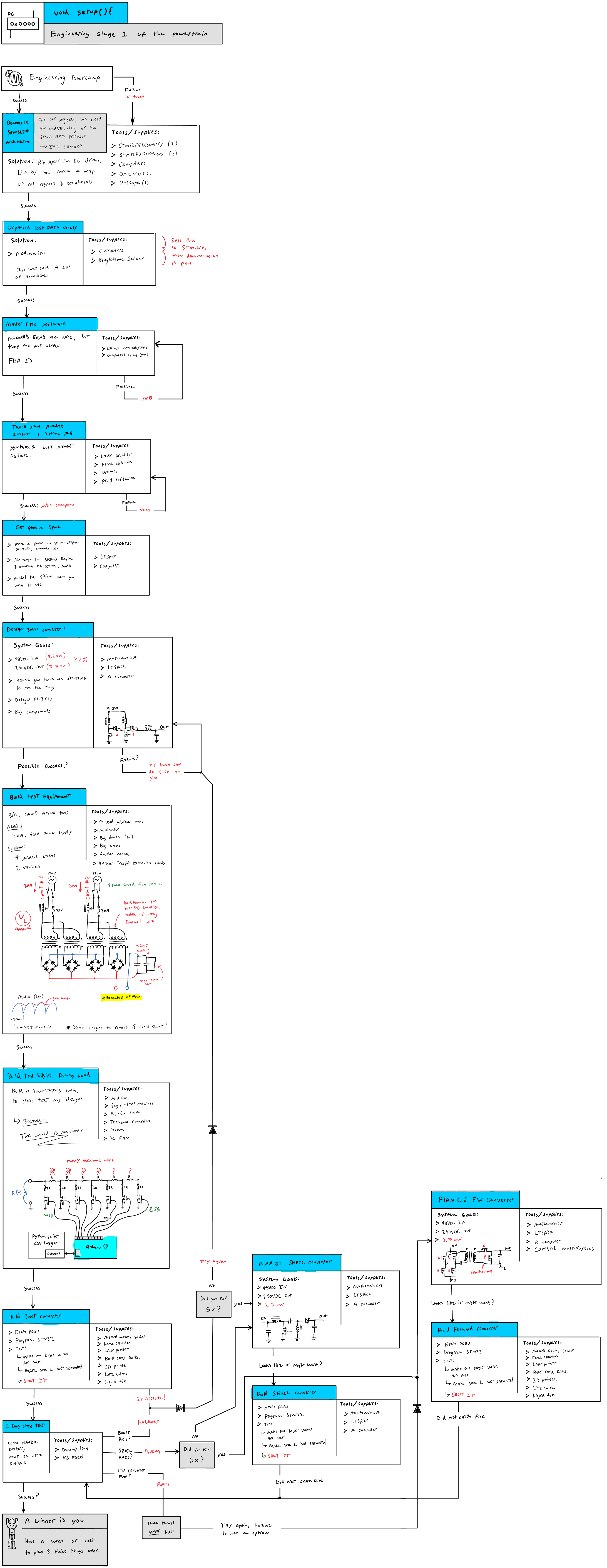
Step 1: Engineering Stage 1 of the power train
![]()
-
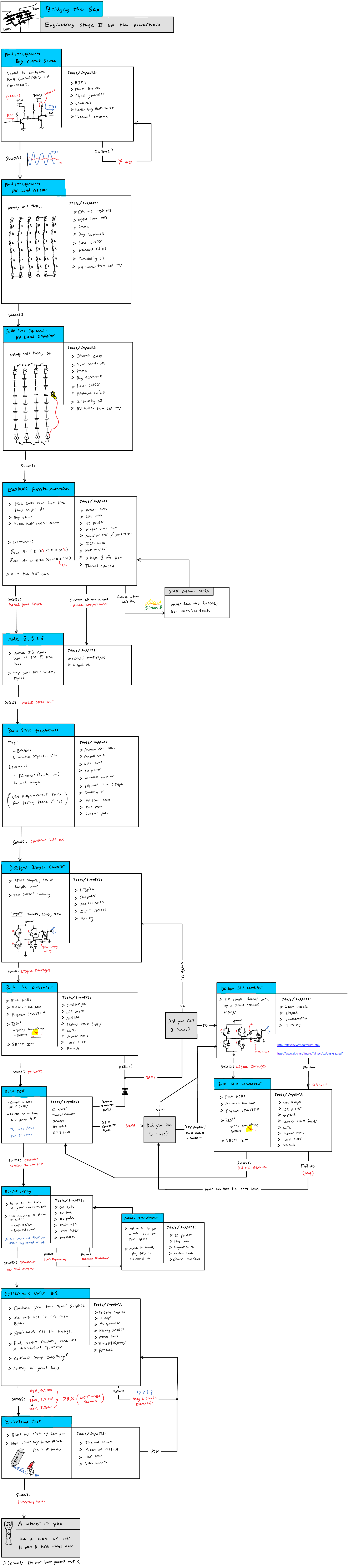
Step 2: Engineering stage 2 of the power train
-![]()
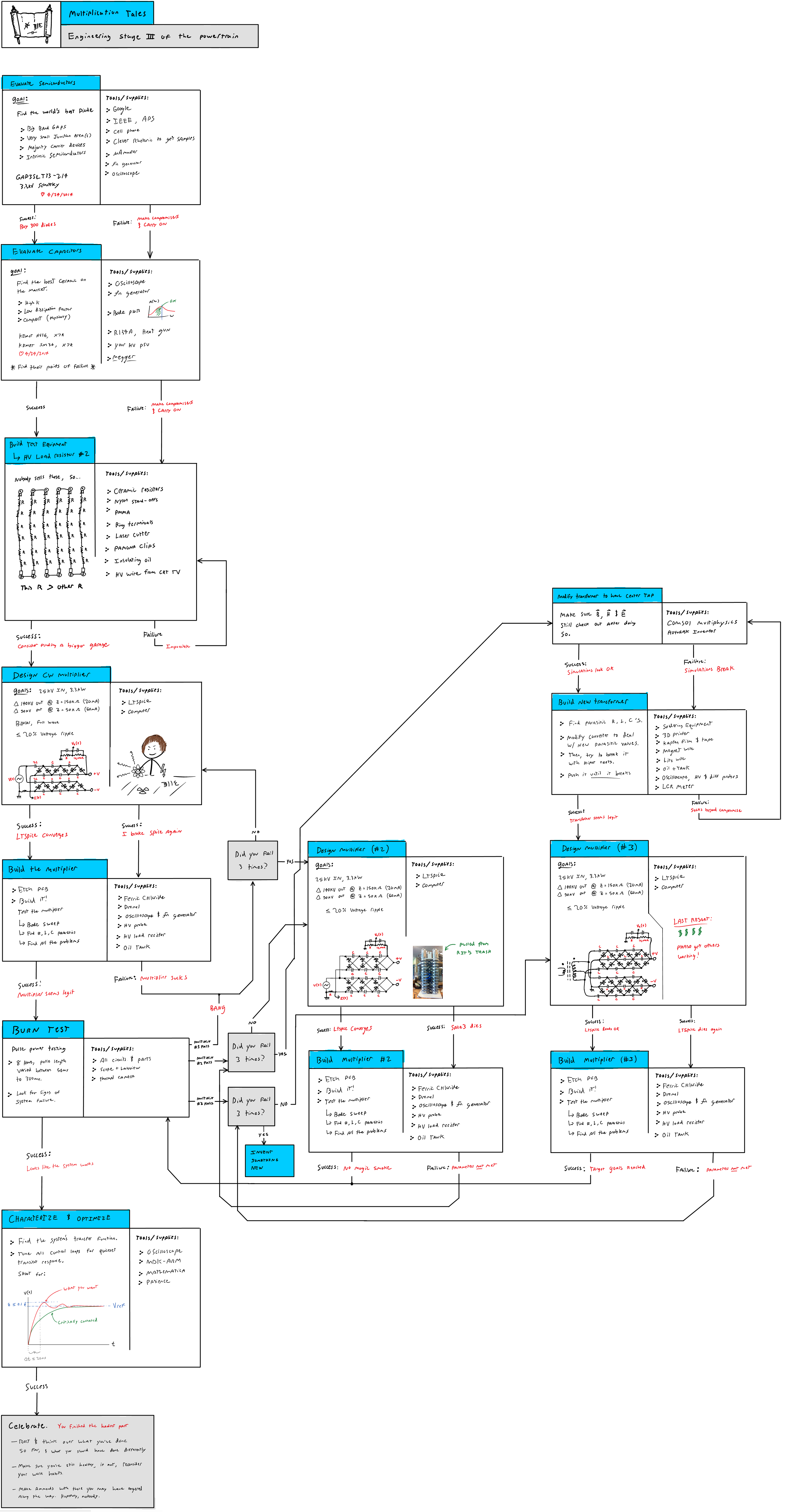
Step 3: Engineering stage 3 of the power train
![]()
-
Step 4: Engineering a modern austin ring transformer
![]()
-
Step 4: Lithium-ion battery shenanigans
![]()
-
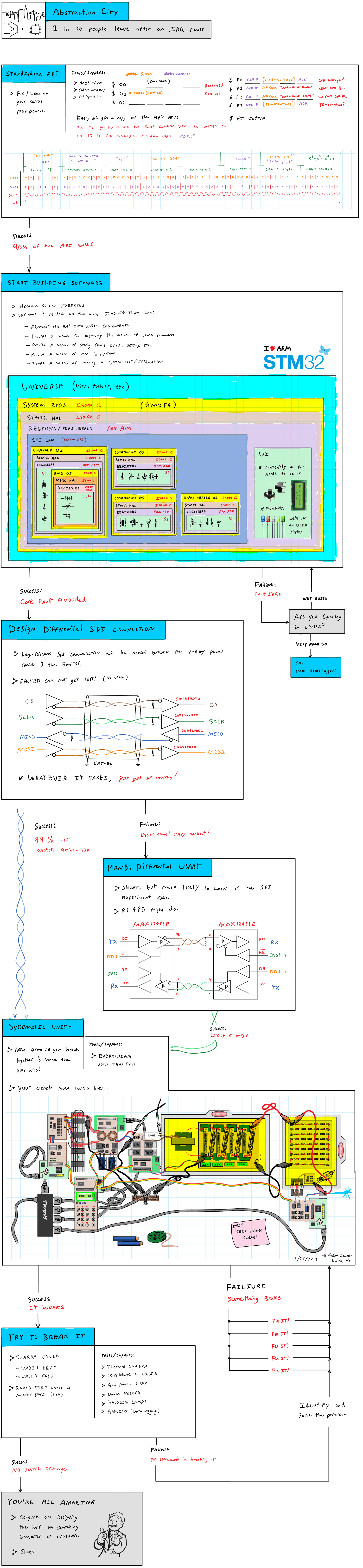
Step 5: Digital controls design
![]()
-
Step 6: X-ray dosimetry
![]()
-
Step 7: Prototyping an x-ray tube designed for this purpose
![]()
-
  _       _   _           _                 _
 (_)___  | |_| |__   __ _| |_   _ __   ___ | |_
 | / __| | __| '_ \ / _` | __| | '_ \ / _ \| __|
 | \__ \ | |_| | | | (_| | |_  | | | | (_) | |_
 |_|___/  \__|_| |_|\__,_|\__| |_| |_|\___/ \__|_
   __ ___      _____  ___  ___  _ __ ___   __|__ \
  / _` \ \ /\ / / _ \/ __|/ _ \| '_ ` _ \ / _ \/ /
 | (_| |\ V  V /  __/\__ \ (_) | | | | | |  __/_|
  \__,_| \_/\_/ \___||___/\___/|_| |_| |_|\___(_)
Along with LOLrioKart speeding past the ivory tower, some parts of this are worth explaining further.
-
Austin ring transformer:
When operating an x-ray tube, it's often the case that you do so in a manner that is "center grounded" so to speak. The anode receives +V, the cathode -V, and, any insulation used only needs to withstand V, and not 2V.
Unfortunately, this means you must provide an isolated 3V source for the tube's heated cathode, which must withstand -V plus some safety margin. Typically this is done with an "austin ring" transformer, but those are big and heavy, so, this is my switch-mode replacement. :-D
![]()
-
High voltage source:
This would be the switch mode power supply topology used inside the x-ray source. It consists of a lithium ion battery stack, boosted to a few hundred volts by a polyphase boost converter, then boosted further using a series-resonant H bridge inverter. Note, the CDE capacitor in series with the H bridge's load, is chosen such that it cancels out the transformer's leakage indutctance, and provides an overall lower impedance for the power supply.
This is then fed into a voltage multiplier, which provides the extreme potentials needed for the x-ray tube.
![]()
-
But, after showing this work to many folks in Rochester, NY, I soon realized that I wasn't going to get very far there. Despite being a healthcare powerhouse, ROC isn't quite the right place for people to talk about hardware technology, especially so, given Kodak and Xerox are both on their way out.
So... I dropped out of university, and bought a trailer.
![]()
-
March 2014 - Designs and a Proposal
08/14/2015 at 19:13 • 0 commentsWhen I was 15, for reasons I'm still not yet sure of, I let some folks in an IRC channel convince me it was a good idea to design a battery powered x-ray system. I accepted the challenge, and over the course of the next year, learned all that was necessary to build such a device.
Then, I built one. Composed mostly of parts from old power supplies, televisions, and what I could buy on ebay, it wasn't the prettiest x-ray source, but, it did in fact work.
-
X-Ray Mk. 1
![]()
![]() -
-But, didn't do a whole lot afterward with it.
In March of 2014, after finishing up a new hackerspace project at RIT, I learned of a WHO study that reported only 1/3 of the world's population has access to medical radiography. For a century-old technology this seemed absolutely absurd, and so, I took interest in solving that obscure, yet very real, problem.
Over the course of a month or so, I drew some artwork detailing what an ideal x-ray solution could look like, both inside and out. I did my best to design things piratically, given the current state of power electronics and x-ray technology.
-
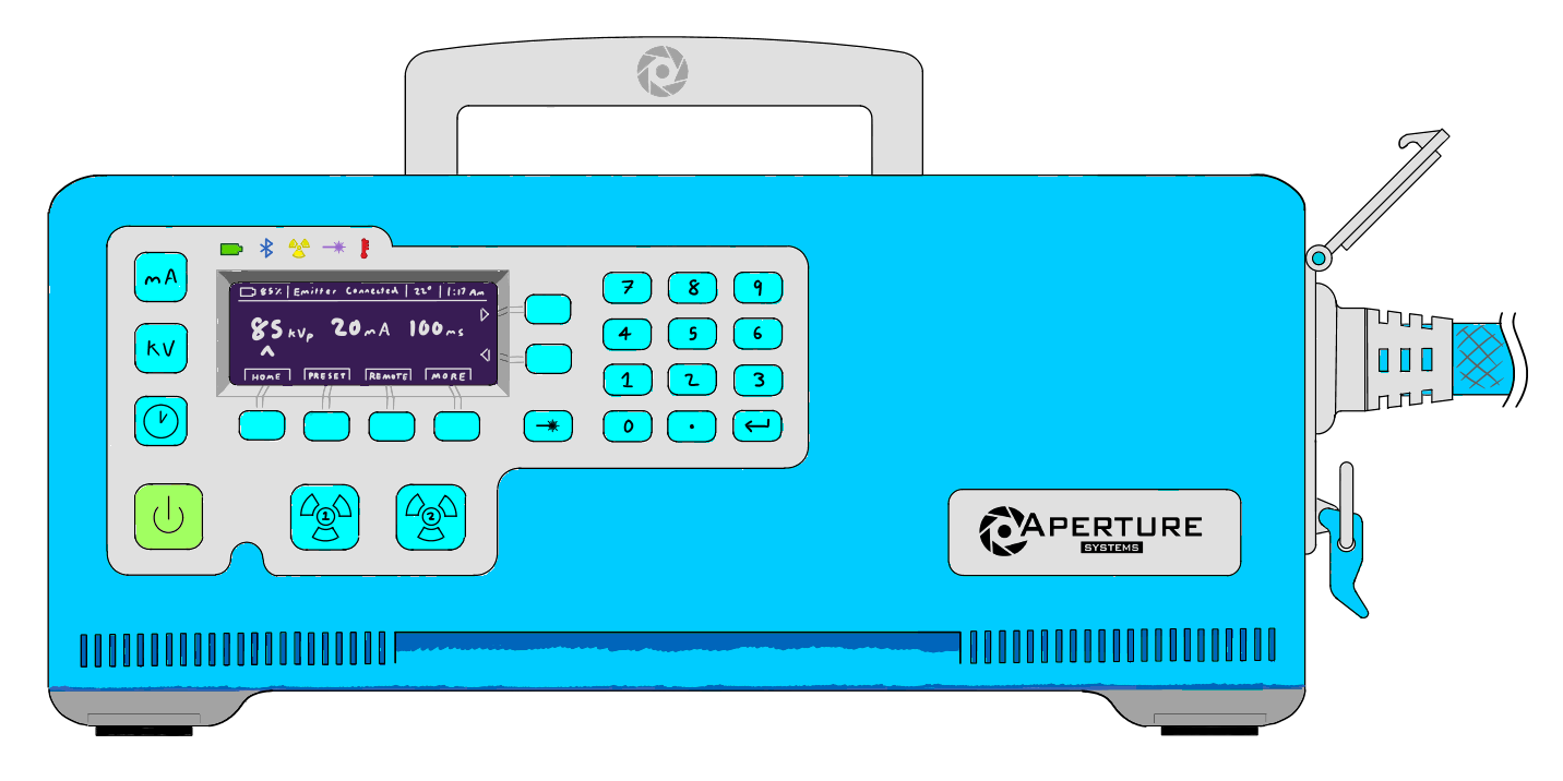
Power Source Front
![]()
-
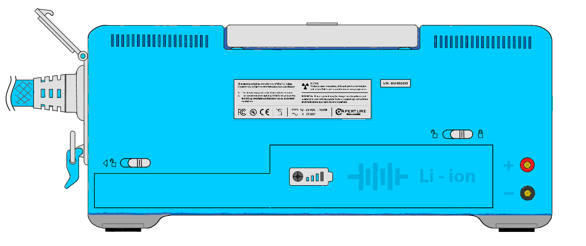
Power Source Back
-![]()
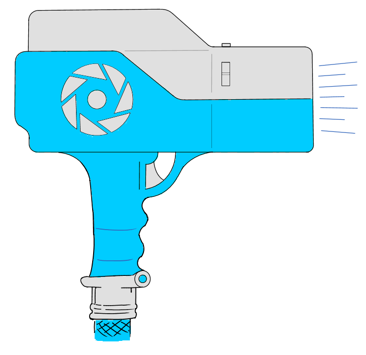
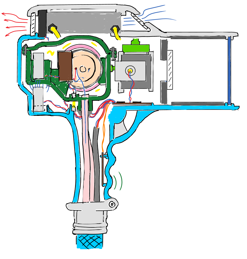
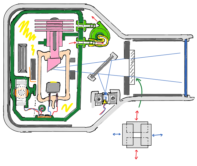
X-ray Emitter 1
-![]()
X-ray Emitter 2
![]()
-
X-ray Emitter 3
![]()
-
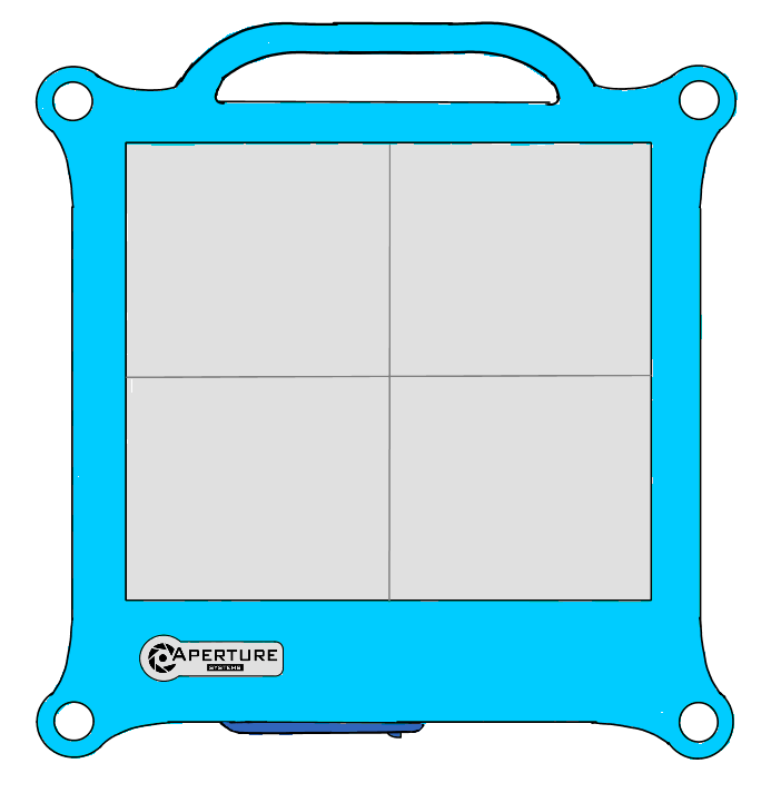
X-ray Detector 1
![]()
-
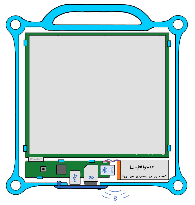
X-ray Detector 2
![]()
-
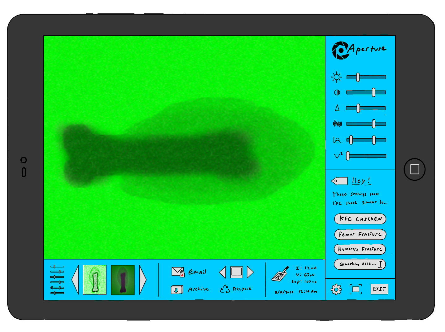
User Interface
![]()
-
Following this, I put together a proposal which described in detail the proposed machine, how persons would operate the device, and, about how much it would cost. I was hoping that someone might take interest in working with me, to build it.![]()
-
What were the results of this proposal?
Unfortunately, a whole lot of raised eyebrows, "nice idea kid" comments, and nothing more.
At the time, I thought this meant that I hadn't done enough research into the subject, or, explained exactly why a 19 year old student would be capable of designing such a device. And so, I went on to do more research, to build a more convincing case that this was possible...
Low Cost X-Ray Systems for Developing Nations
This is the result of 3,500 man-hours of labor and love, but we need your help to push it forward, HAD community


 -
-