-
1Step 1
These instructions are to build exactly what I have prototyped. Since this technology is highly customizable, different containers or materials can be used to scale the device to whatever application needed. There is much room for creativity here.
Cyclonic Self-Induced Spray Wetscrubber Instructions
The wet scrubber is what is used to filter out fine particulates and some VOC's out of the air (fine meaning everything greater than 2um). The wet scrubber is comprised of two parts, the hollow walled tube assembly, and the wet scrubber housing. The hollow walled tube assembly is comprised of an inner tube that has inward and outward spiraling holes, an outer tube that covers the inward spiraling holes, an inlet pipe that connects to the outer tube, and a mist eliminator bowl.
To build the wet scrubber section you'll need thick walled ABS or PVC pipe and several plastic containers: two to make a hollow walled tube, one to make the mist eliminator, and another larger one to house the hollow walled tube assembly. The housing bucket can be either a 5 gallon bucket or 3 gallon bucket depending on your application. The housing bucket will need to be about a foot high and wide enough to be able to fit a hollow walled tube in the center of it along with several inches of clearance.
Hollow Walled Tube Assembly
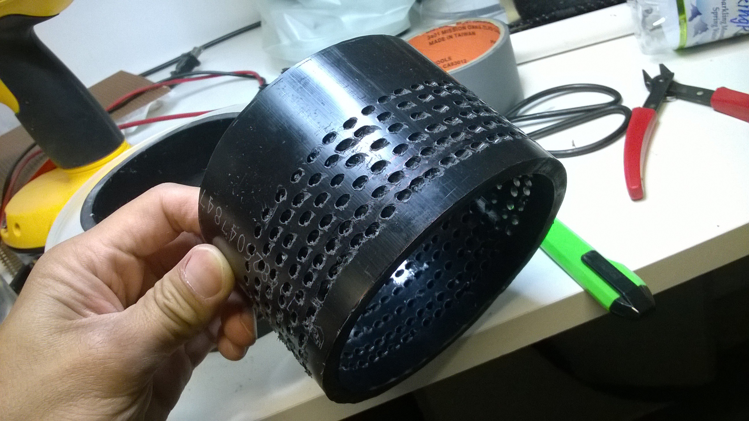
Lets begin by building the hollow walled tube. Take the 4" diameter ABS pipe and cut two 4" lengths from it. Then drill at least 6 rows of holes that spiral inwardly. This can be done by placing the tube section on a drill press such that the drill bit enters tangentially to the wall of the pipe. The number of holes must be greater than the total cross sectional area of the smallest air piping you will use. For example if I were to add up the space from all the little holes, it would be bigger than the cross sectional area of the air inlet pipe. For the other ABS pipe section, drill the holes to spiral in the opposite direction as that of the first ABS pipe section. This is is done so the air that enters the hollow walled tube will continue to spiral in the same direction as it exists the tube.
-
2Step 2
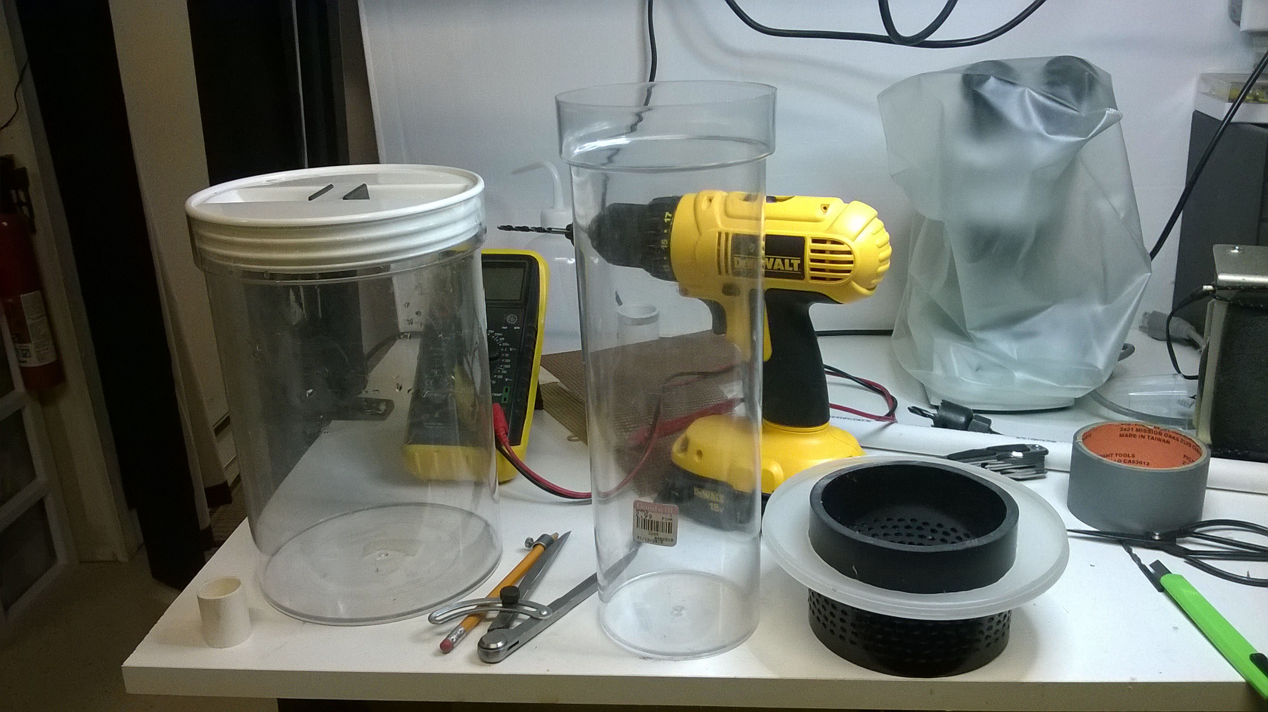
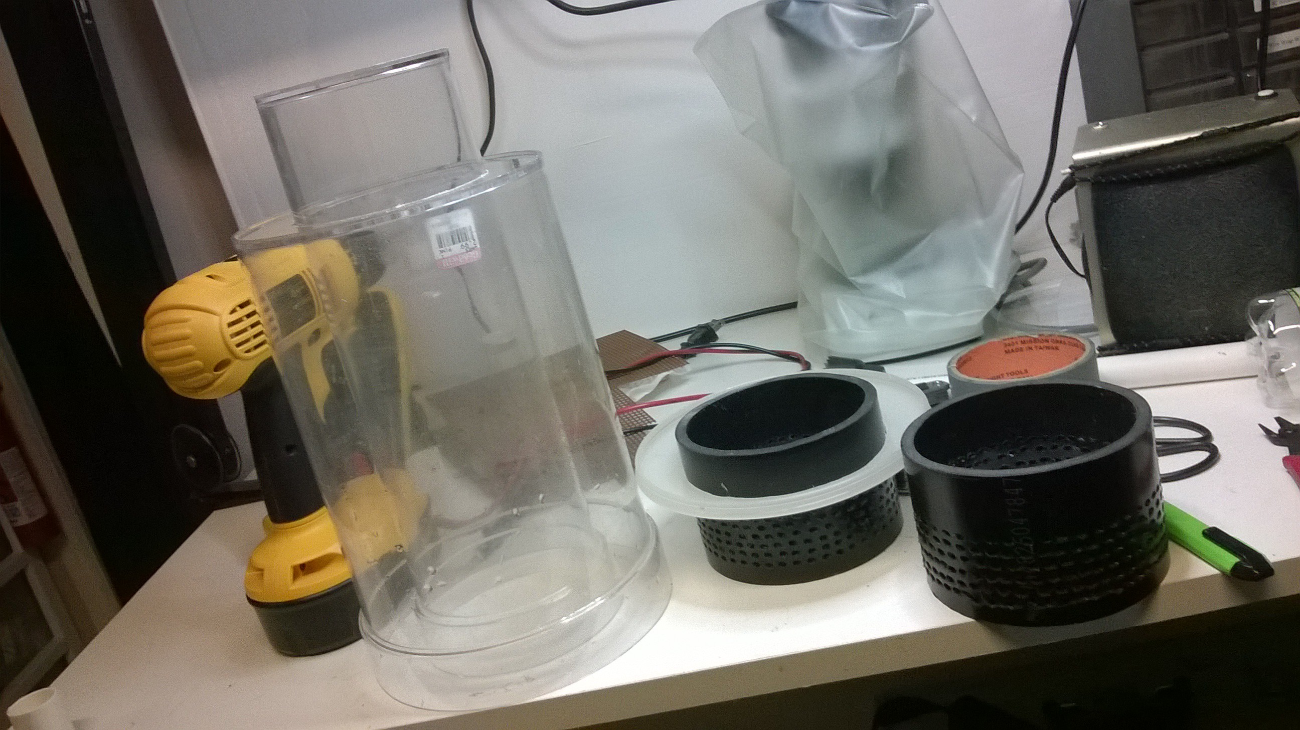
Next take a cylindrical plastic food storage container that has the same diameter as the 4" ABS pipe and cut the bottom off of it. You can also simply not cut the ABS pipe and keep it as one piece to form the inner wall of the hollow walled tube. I chose clear containers so I could see inside while it is operating. You will want the length of the hollow walled tube to be shorter than the wet scrubber housing (the bucket) such that the lid can fit on it and seal the wet scrubber housing.
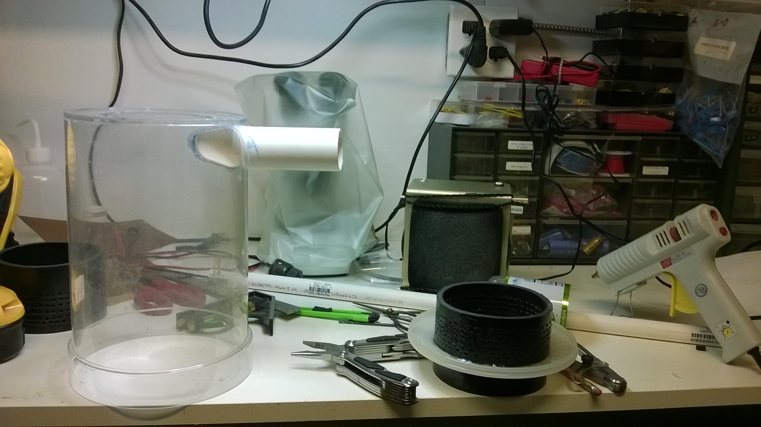
Then take a larger cylindrical plastic food storage container that is of larger diameter and cut out a 4" diameter hole out of the lid and the bottom such that the narrower cylindrical container can fit inside.
 Note that inserting the narrower container into the larger one creates a hollow walled tube.
Now glue to lid of the larger container (which has a 4" hole in it and
is now a ring) to the 4" ABS pipe section using hot glue or solvent.
 -
3Step 3
Next an inlet port is cut out of the outer wall of the hollow walled tube (the larger container. I first cut a rough curve on a PVC pipe then butt it up against the tube and traced its profile to get the size of hole needed. Using a rotory tool, drill out the inlet hole to the hollow walled tube.
 Then glue a 1 1/4" PVC pipe to the oval hole to act as an inlet port.
-
4Step 4
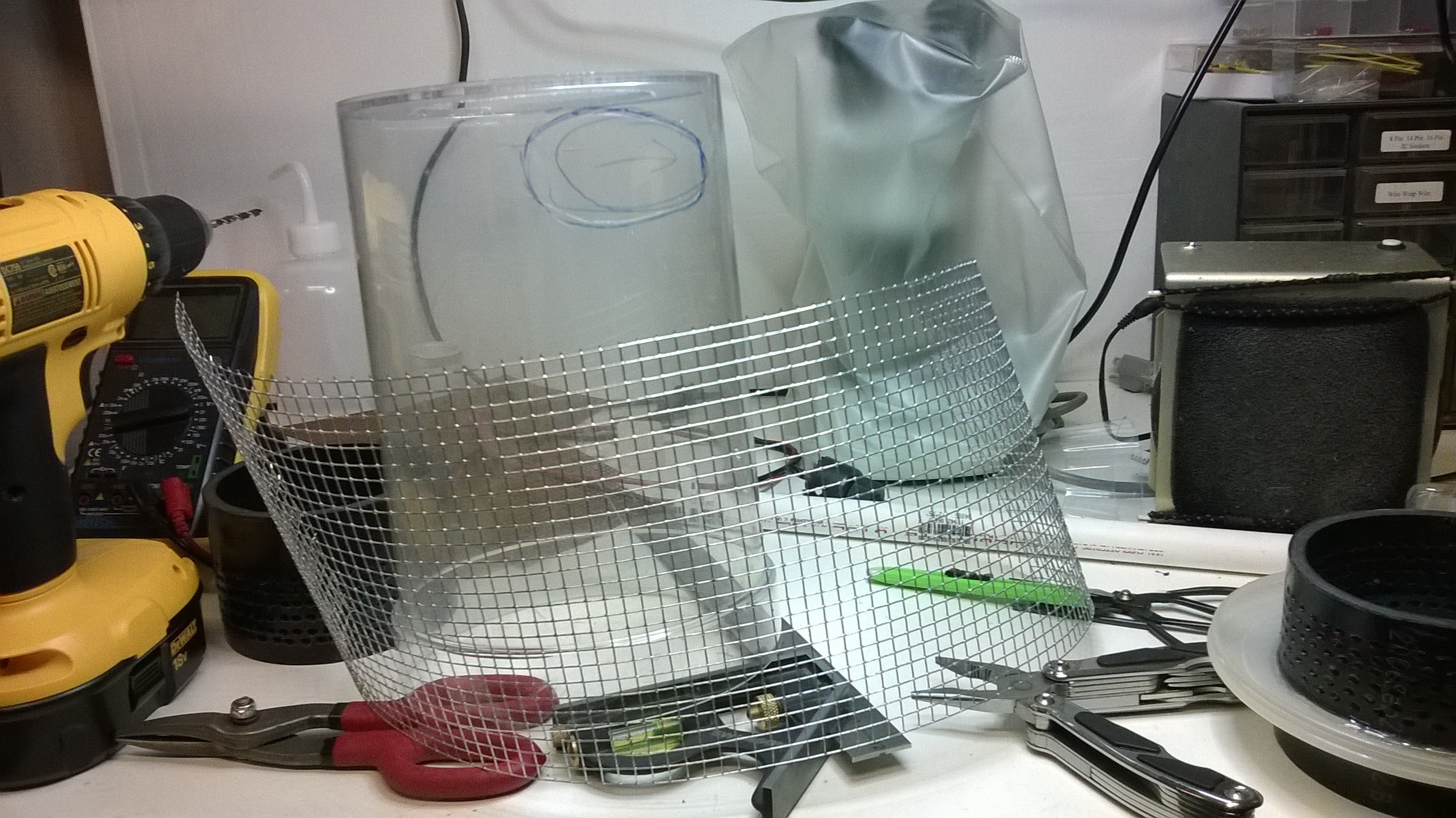
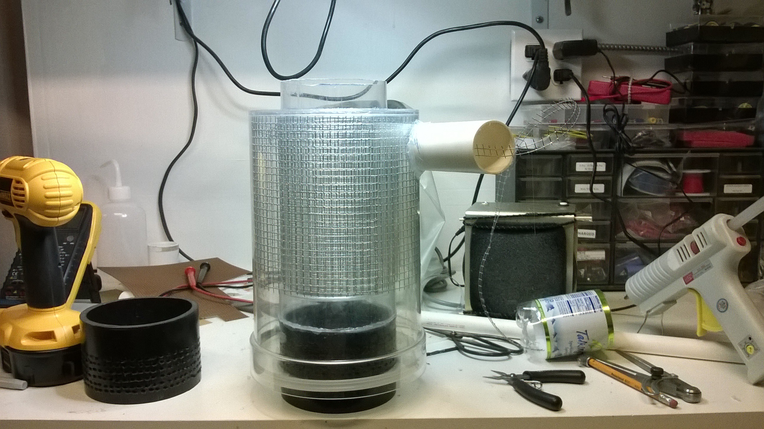
Then attach the bottom 4" ABS pipe sections containing the lid glued to it to bottom of the hollow walled tube thereby sealing it. (disregard the metal cage inside)
Now glue the other 4" ABS pipe section to the top of the hollow walled tube.(disregard the metal cage inside)
Make sure the inward spiraling holes of thebottom 4" ABS pipe section is opposite direction to that of the top 4"
ABS pipe so to form a continuous spiral path for the air.For example, if the holes of the 4" ABS pipe section are both spiraling clockwise (looking down into the tube), the air will enter clockwise but have to exit counter clockwise which is not advisable.
-
5Step 5
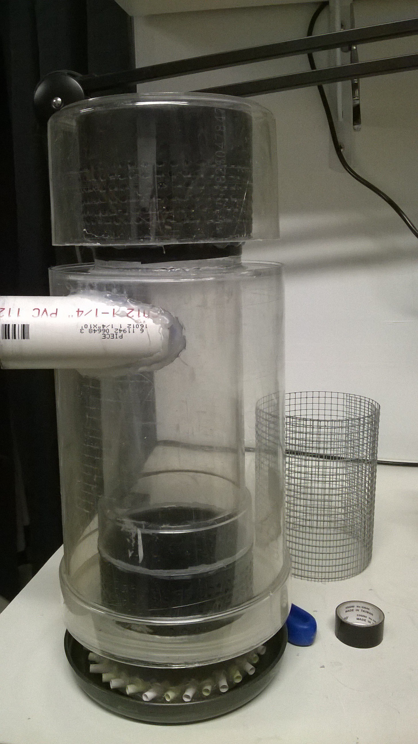
Now find another bowl like container that is of the same diameter or larger as the outer wall of the hollow walled tube. The container must be as deep as the rows of holes drilled into the 4" ABS pipe section. This bowl like container will form the mist eliminator since the exiting air will impact this container and direct the air downward.
Glue the bowl like container to the top of the 4" ABS pipe section to form a mist eliminator.

-
6Step 6
The Wet Scrubber housing
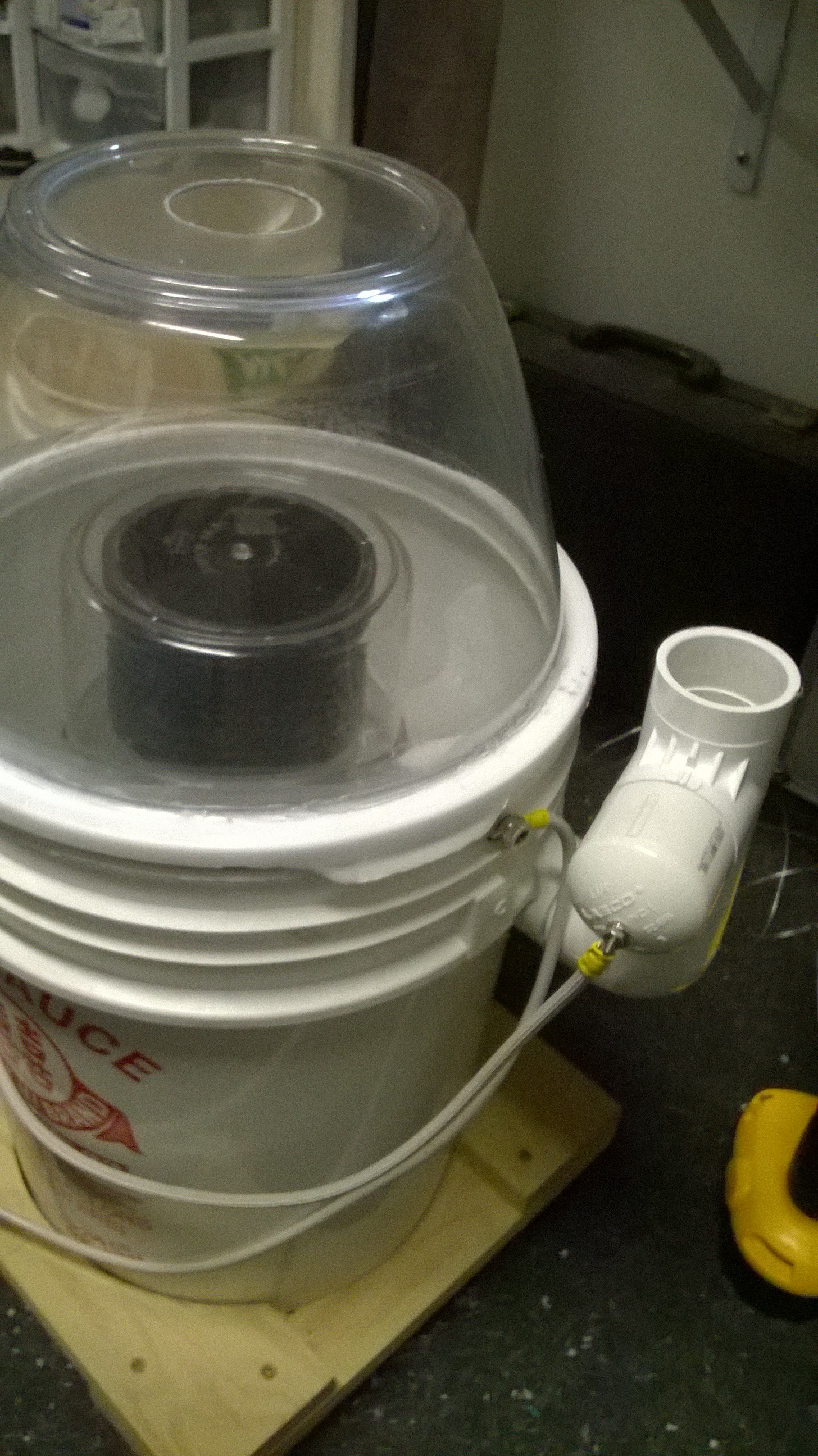
Now the wet scrubber housing will be built. The housing is simply a 5 gallon bucket. A 2" hole will need to be drilled into it such that the inlet pipe of the hollow walled tube can connect to it.
Drill a 2" hole using a hole saw. If using a round bucket, angle the hole slightly such that when the hollow walled tube inlet pipe is interfaced to it, the tube will be centered within the bucket.
Glue a 1 1/4" PVC pipe coupler in this hole. This allows the hollow walled tube to be plugged or unplugged from the coupler in case it needs to be serviced. I used epoxy puddy to fasten this coupler into the hole.
-
7Step 7
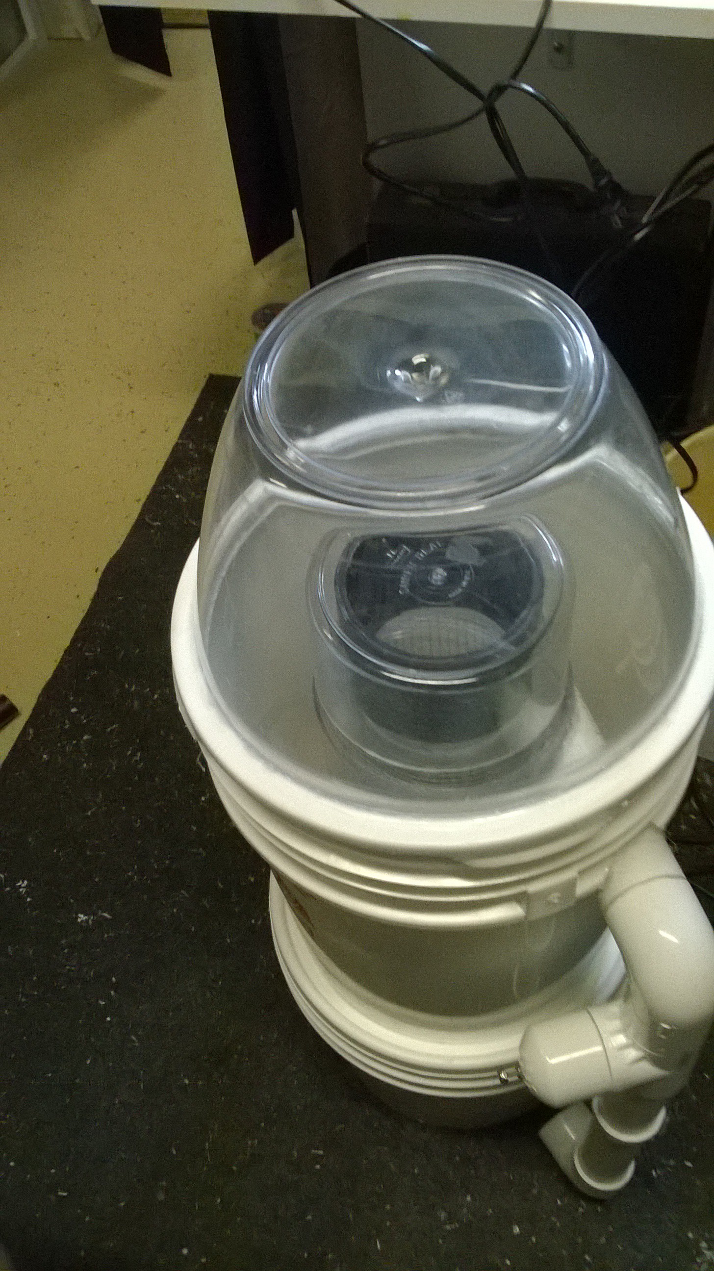
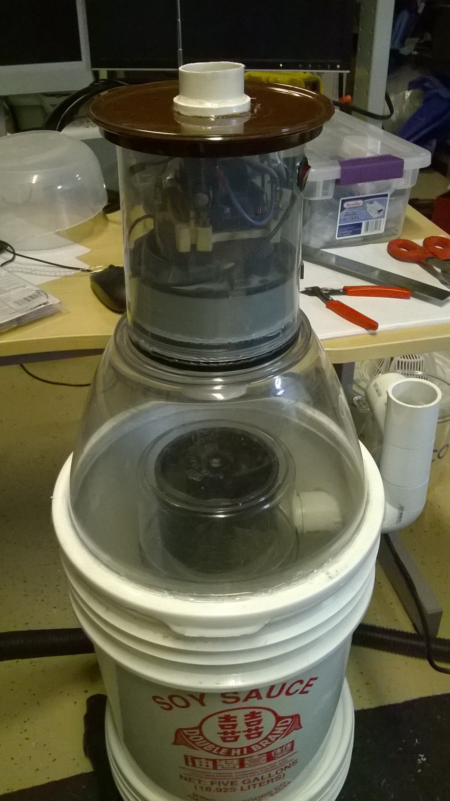
Ensure the lid can seal the bucket with the hollow walled tube assembly installed inside it. Since my hollow walled tube was too tall for the bucket, I used a salad spinner container to act as my lid. I cut a large hole out of the original bucket lid glued the salad spinner bowl in place of the hole.
Drill a 2" hole in the lid with a hole saw. This is where the air will exit.
-
8Step 8
The Blower Motor
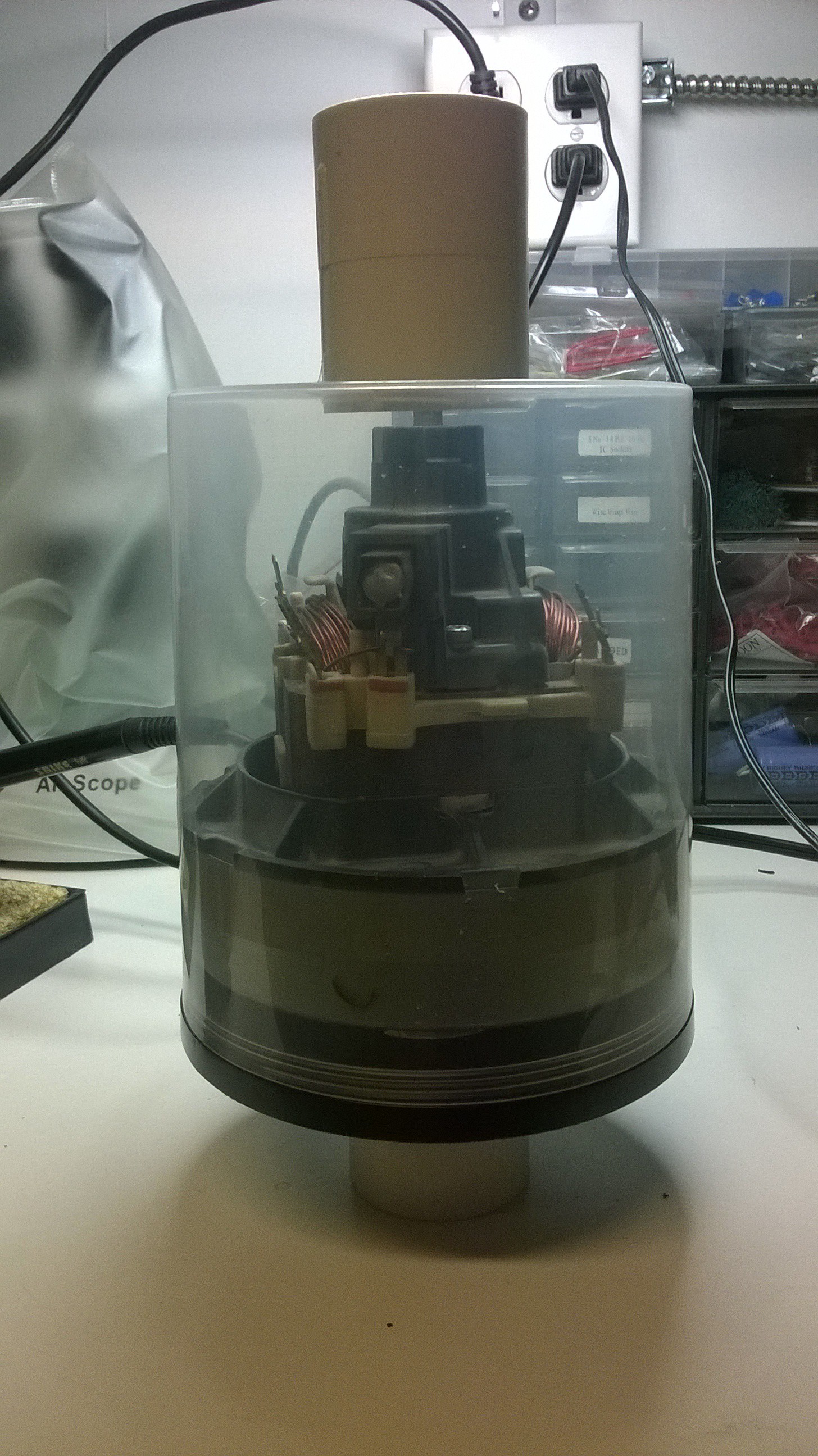
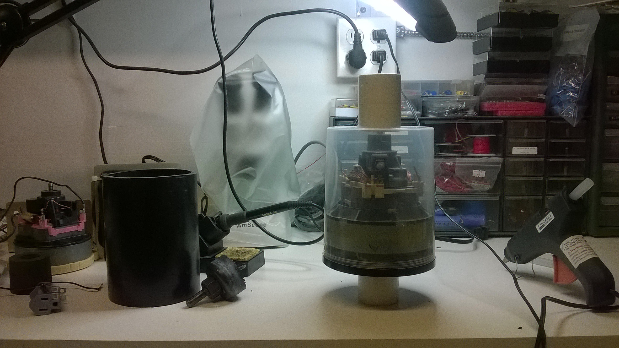
To move the air, I used a vacuum motor that was salvaged from an old upright vacuum cleaner. These type of motors conveniently fit inside a 100 CD plastic cake box spindle container. Drill a 2" hole on the top of the clear portion of the CD case as well as the bottom of the spindle. Next glue two 1 1/4" PVC couplers to these holes. Wedge the vacuum motor inside and glue the CD container shut.

You will want to make a small hole in the CD case so the vacuum motor's power cord can be routed through it. It is also a good idea to wire a power switch to the motor. Seal the cable and switch holes with hot glue or solvent glue.
-
10Step 10
DIY Tube Electrostatic Precipitator Stage Instructions
To scrub out ultra fine particulates (particles less than 1um), the wet scrubber is connected to an electrostatic precipitator as a separate stage. Here are the instructions of how I built my exact prototype. Once again there is much room for creativity. If I were to do this prototype over again, I would use square pipes as it would reduce the amount of fabrication work significantly.
The tube electrostatic precipitator is comprised of segments of metal tubes that are placed side by side in parallel, wires inside the tubes that produce corona, a housing to contain all of the tubes, and a high voltage supply circuit to power the precipitator. Each tube segment contains a wire running axially down the center of it as well as support structures on each end of the tube to electrically insulate the central wire from the tube walls. All of the tube wires are connected together in one circuit, and all of the tube walls are connected together in another circuit. These circuits are powered by a high voltage circuit.
The exact dimensions of the tubes and number of tubes is determined by the application and depends on the volume of air flow (ACFM) and the amount of dust loading that will be filtered. This means the higher the air flow or the thicker the smoke to be filtered, the larger the system will need to be to maintain high efficiency of collection. A conservative rule of thumb is to have 35-40 square feet per 100ACFM. The high voltage circuit also must be able to supply enough current to power the amount of surface area required. Larger surface area will not help if the power supply is not able to provide the corresponding amount of corona current to the wires (which is part of the problem I was having in my ESP prototype).
Household Electrically Enhanced Wet Scrubber
A household air purification unit for kitchens, labs, & smokers used to scrub fine particulates and VOC's out of the air.

Discussions
Become a Hackaday.io Member
Create an account to leave a comment. Already have an account? Log In.