-
Finals Video
10/26/2015 at 02:13 • 0 commentsI'm so glad to have made it this far. I don't think I've ever worked this hard in my life. I feel so good to have completed this project! Thank you so much to Hackaday for the inspiration, the motivation, and the opportunity. Thank you to my wife who helped me so much at each step and to my parents who helped build it and to my friends and followers who gave lots of good input and encouragement. Thank you GOD!
-
Putting It all Together
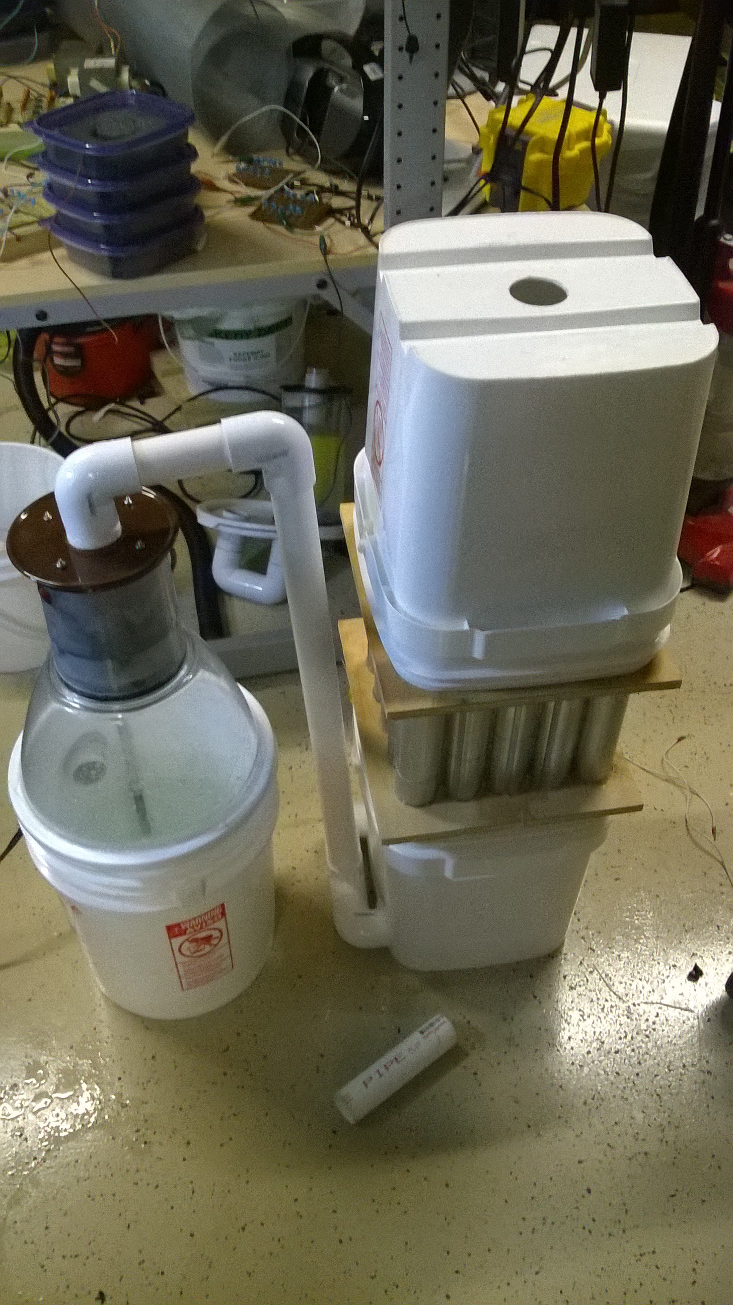
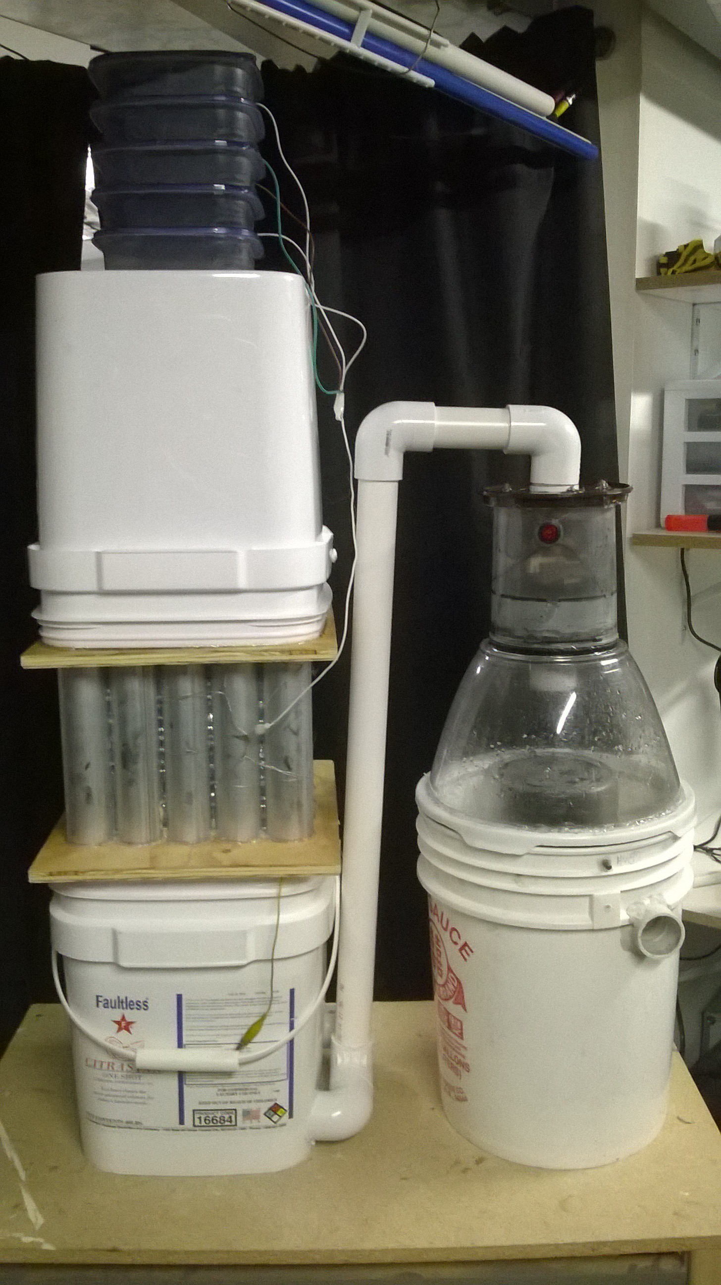
10/25/2015 at 01:26 • 1 commentNow it was time to assemble everything together, the wet scrubber, the electrostatic precipitator, and the activated carbon pods. I pondered for a while on what the order of the devices should be in. I knew I needed to keep the activated carbon as the last stage as it would gum up if it absorbed too many larger particulates. The question was whether to have the wet scrubber as the first or second stage. So far I had the electrical boosting at the first stage and the wet scrubber second. I decided to switch this and place the wet scrubber first as the wet scrubber could scrub all the fine particulates 2um and greater so the electrostatic precipitator could then take care of the ultra-fine particulates 2um and below to finally leave the activated carbon stage to absorb VOC's and any Ozone produced from the electrostatic precipitator.
I simply routed the output of the wet scrubber to the input of the ESP via PVC pipe fittings.
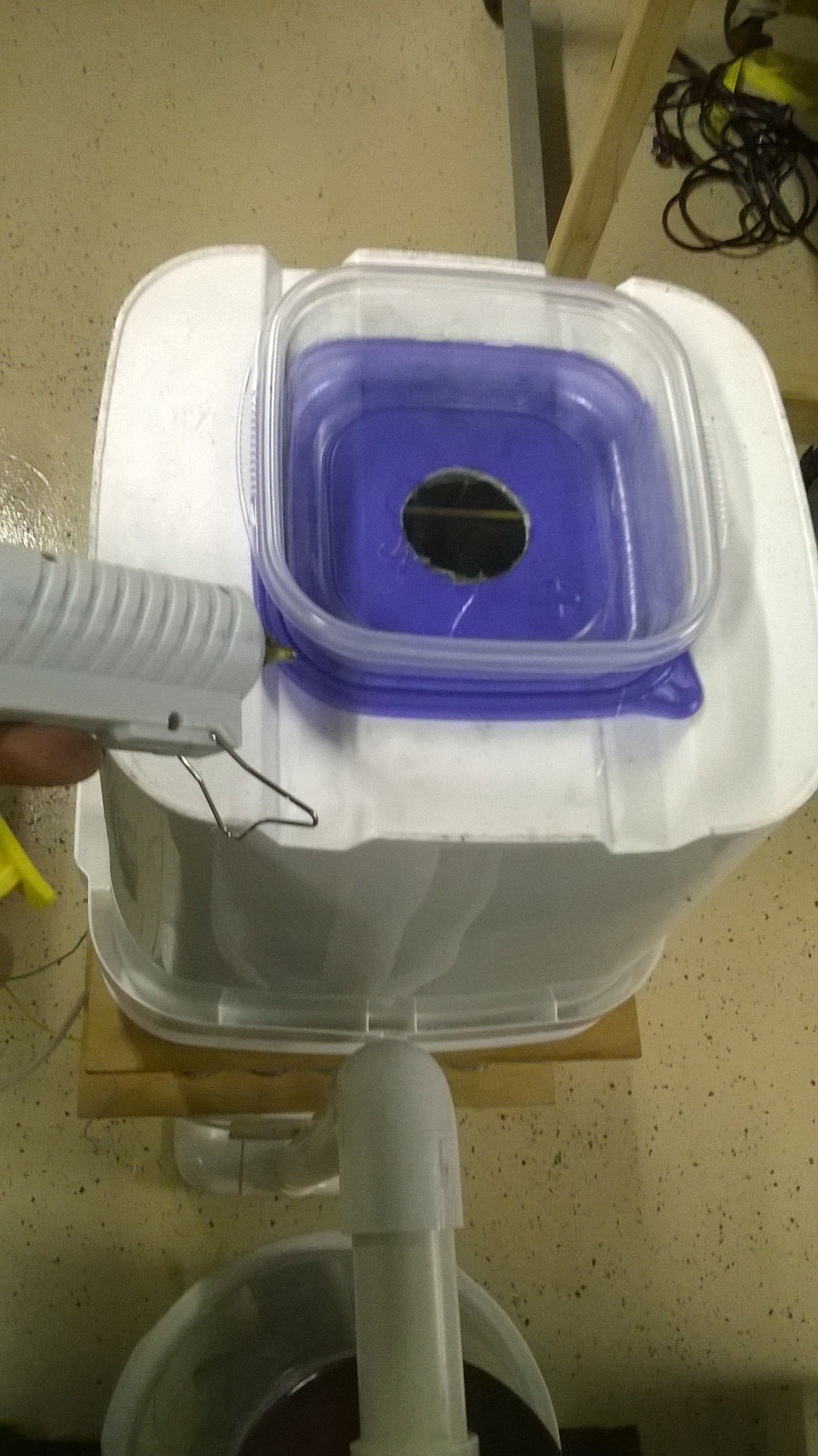
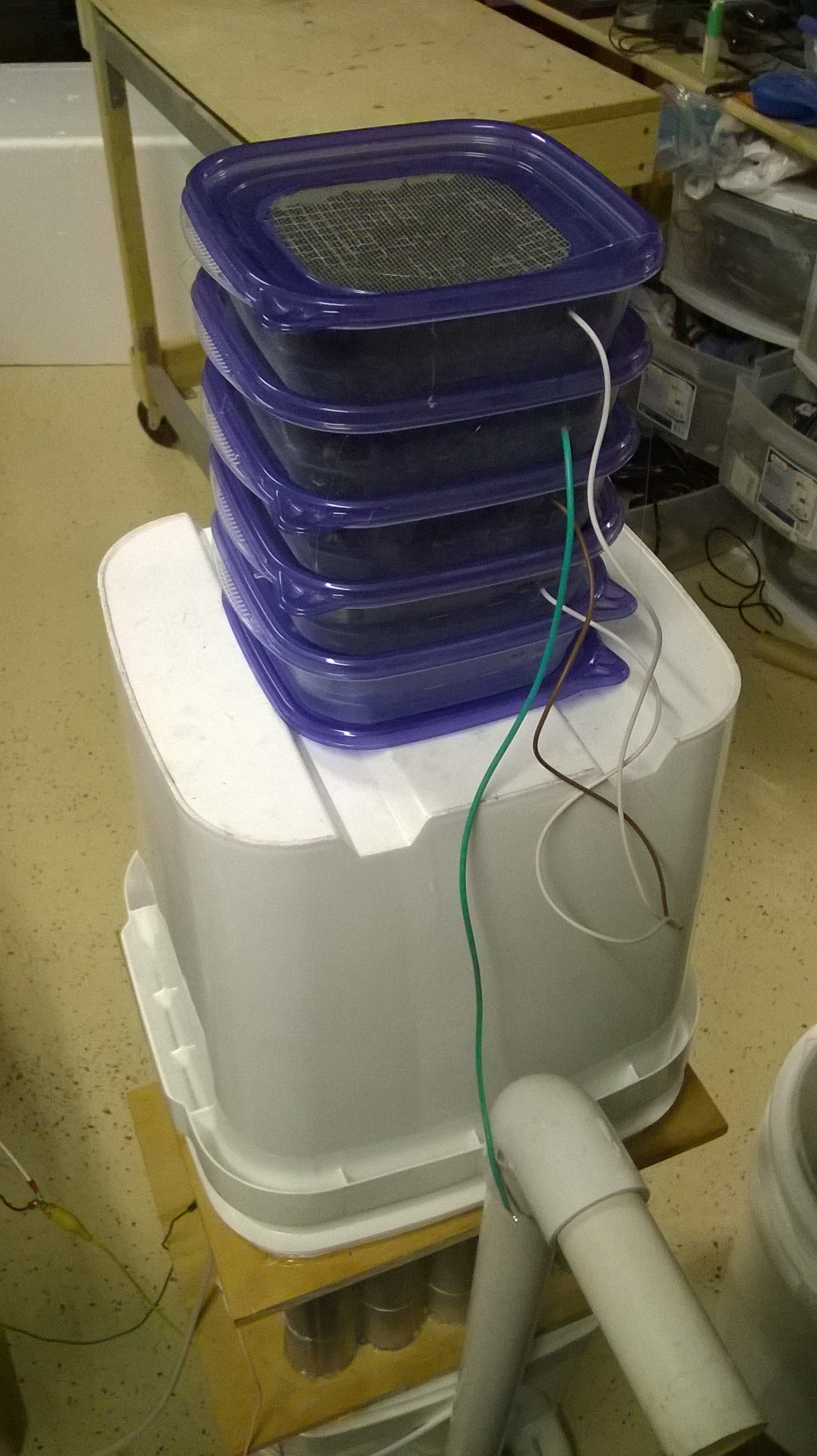
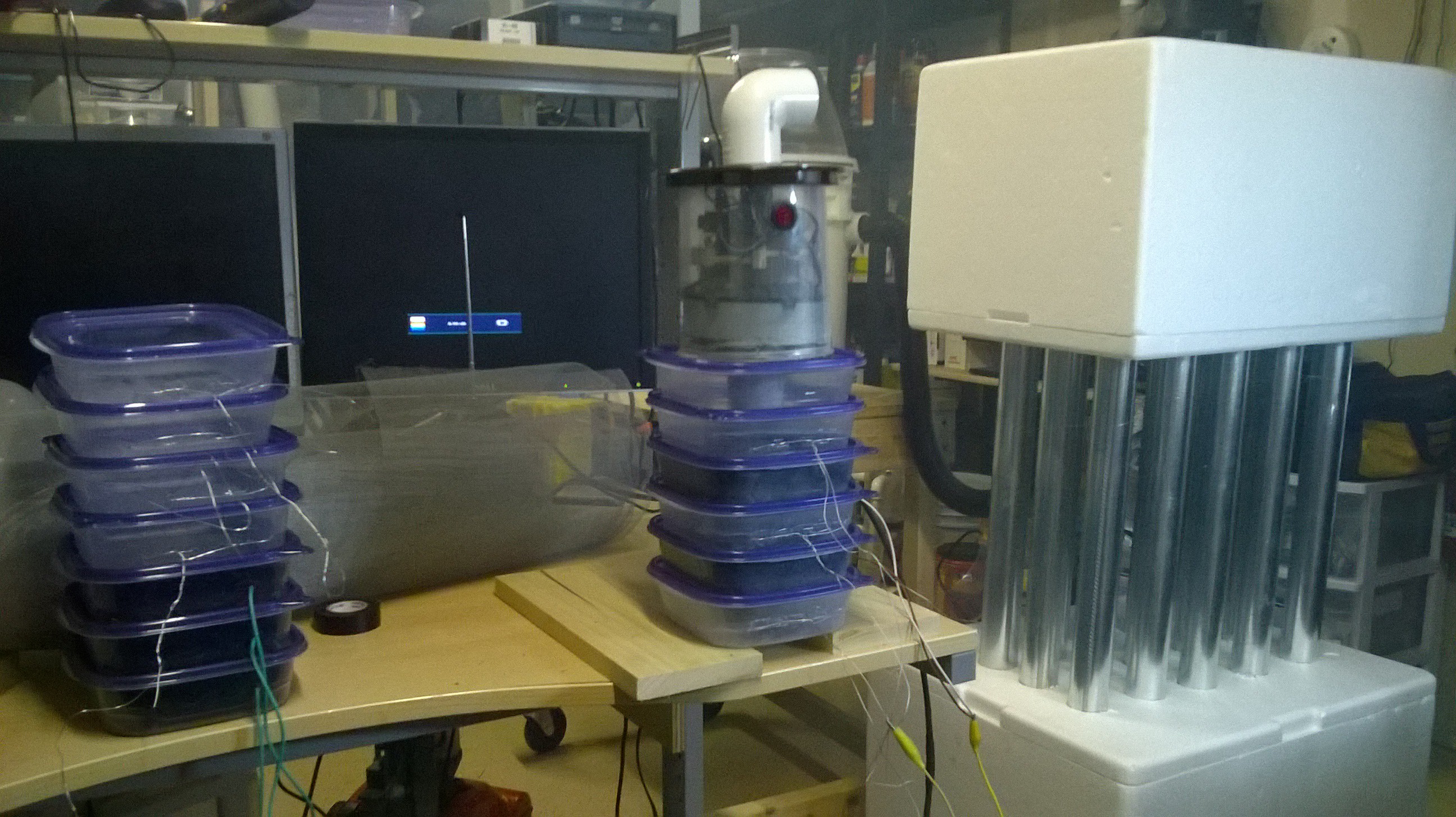
 I then glued a sandwich container to the top of the ESP so the activated carbon pods could interface to them.
  Then I took four activated carbon pods and glued them together into one module, then I mounted it on top of the ESP.
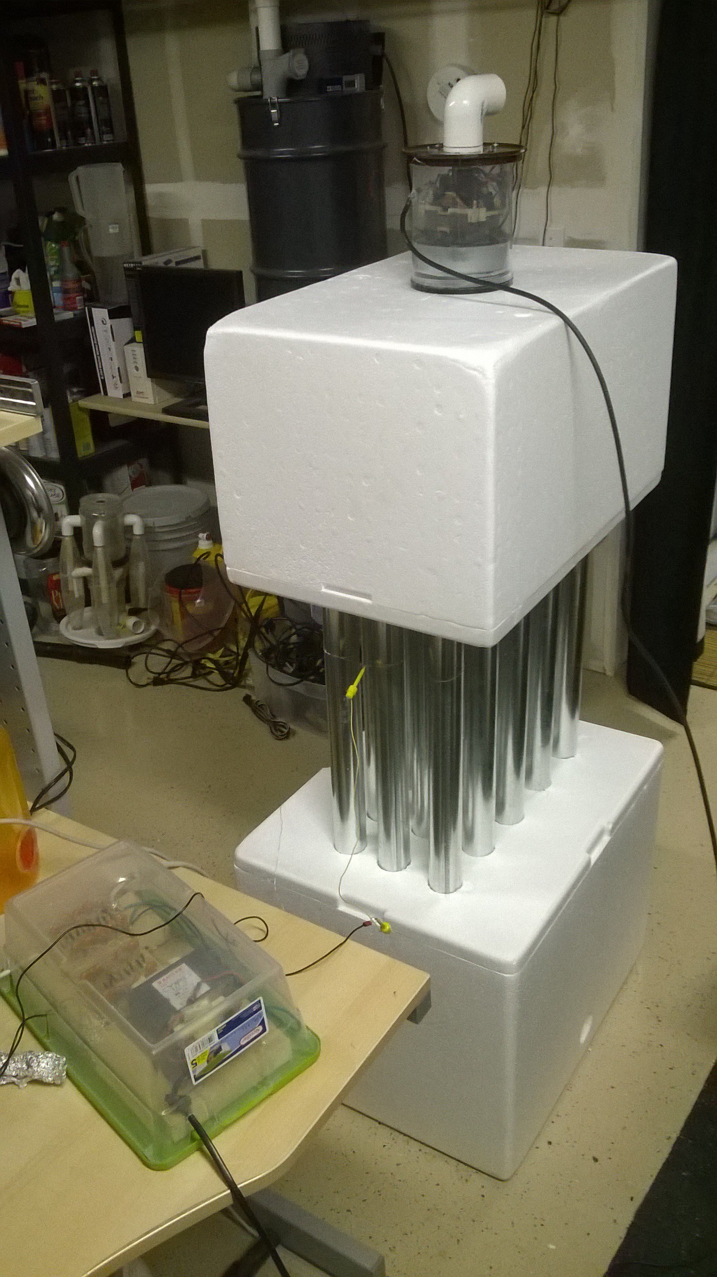
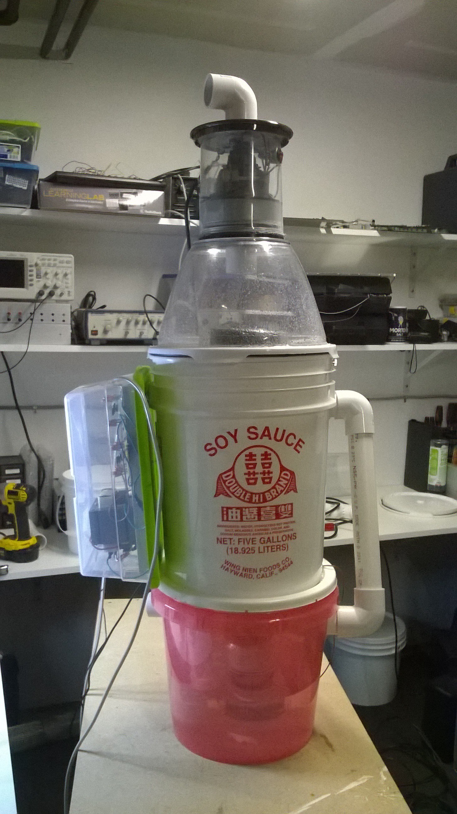
 I decided to use the electrically charged versions of the activated carbon pods and connect the carbon pods to the same polarity as that of the ESP tube walls, this gave additional collection surface for ultra-fine particulates and indeed it did help! Here is the finished unit. A unit of this size could scrub all of the pollutants in my whole workshop or even my house if I connected it to the HVAC system.
There were a few leaks that I needed to hot glue and seal but after connecting everything, the tests were amazing! It worked rather well. I turned the blower motor on and shot the fog machine directly into the input, the fog poored out the output end but when I turned the electricity on, the fog dissappeared! I could make smoke signals with this machine by turning on and off the ESP hahaha! If I turned the blower to full speed I could see some penetration with some fog coming out the end but it wasn't very significant. With more electricity I believe I could easily achieve 99% collection efficiency in a small unit as this! YAAAAAAY it works!
-
Tweaking the Problems
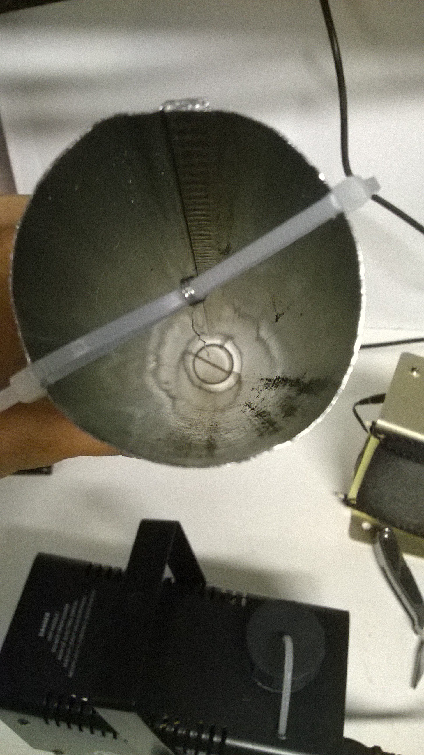
10/25/2015 at 01:13 • 0 commentsI learned two problems over the course of the last few days. One the flow of air needed to be laminar so that the fog could evenly be distributed to all of the tubes. And second the fog I was rather conductive and was slowly shorting out the electrostatic precipitator, particularly at the spot where the wire is suspended by a zip tie to the tube.
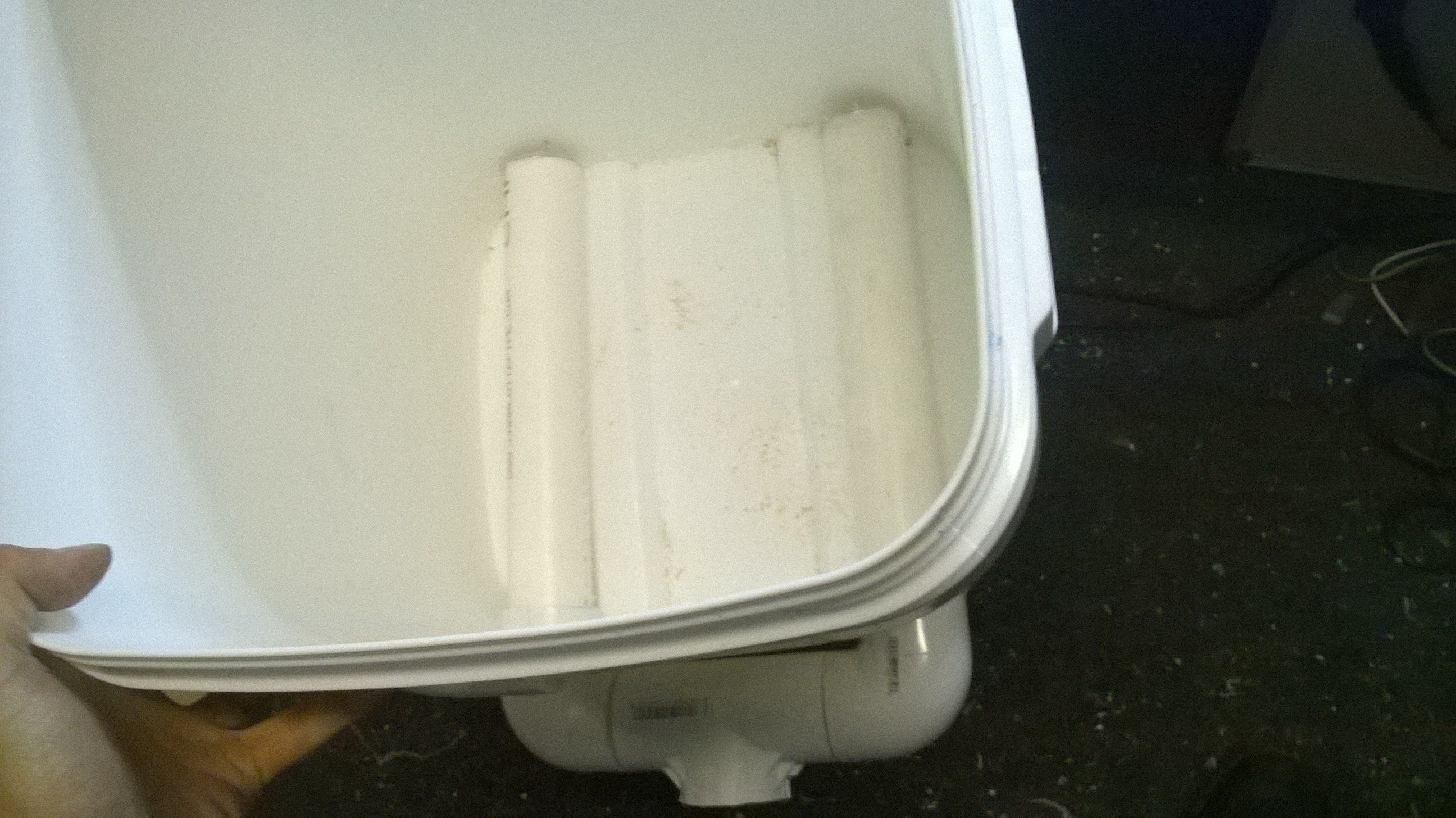
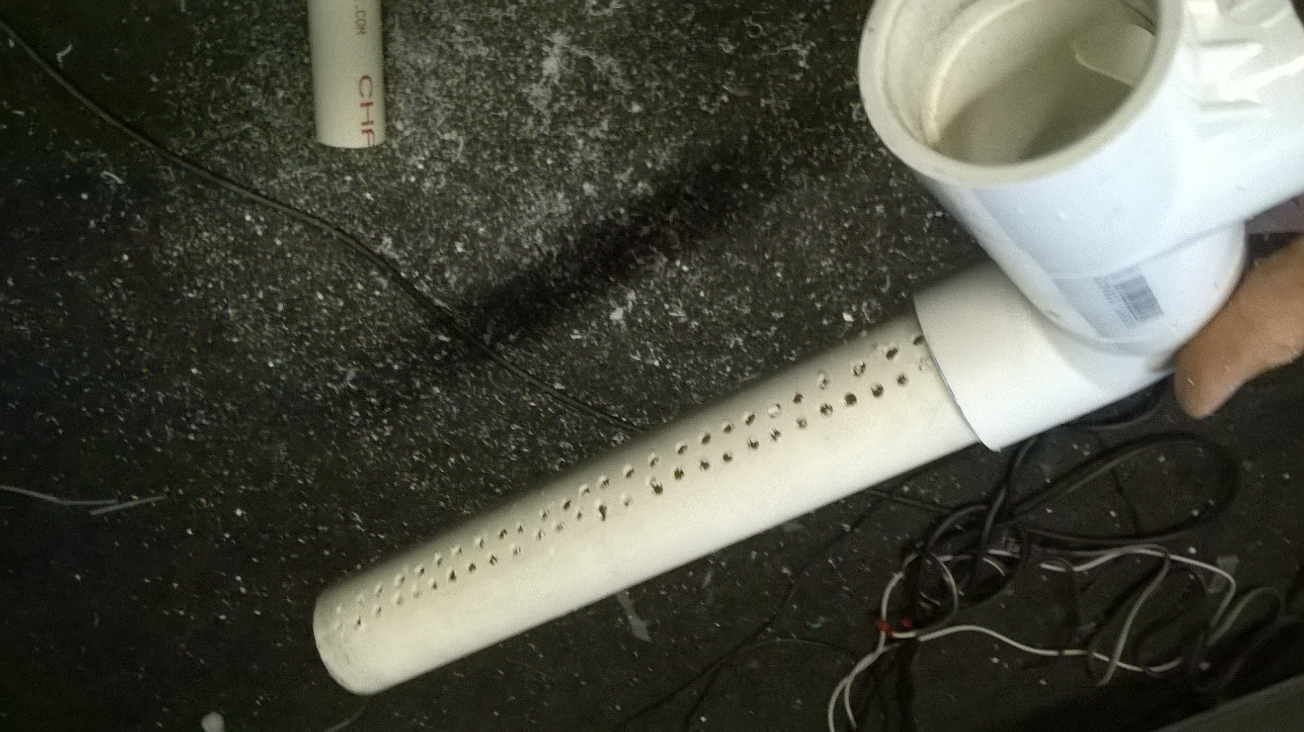
To address the laminar flow problem, I created some baffles and some air distribution pipes in the bottom bucket. This required splitting the air flow intake to two pipes and drilling a series of holes in the pipes so the air would go in all directions more evenly.
 The holes were drilled so the air would enter on a horizontal plan then rise upwards.
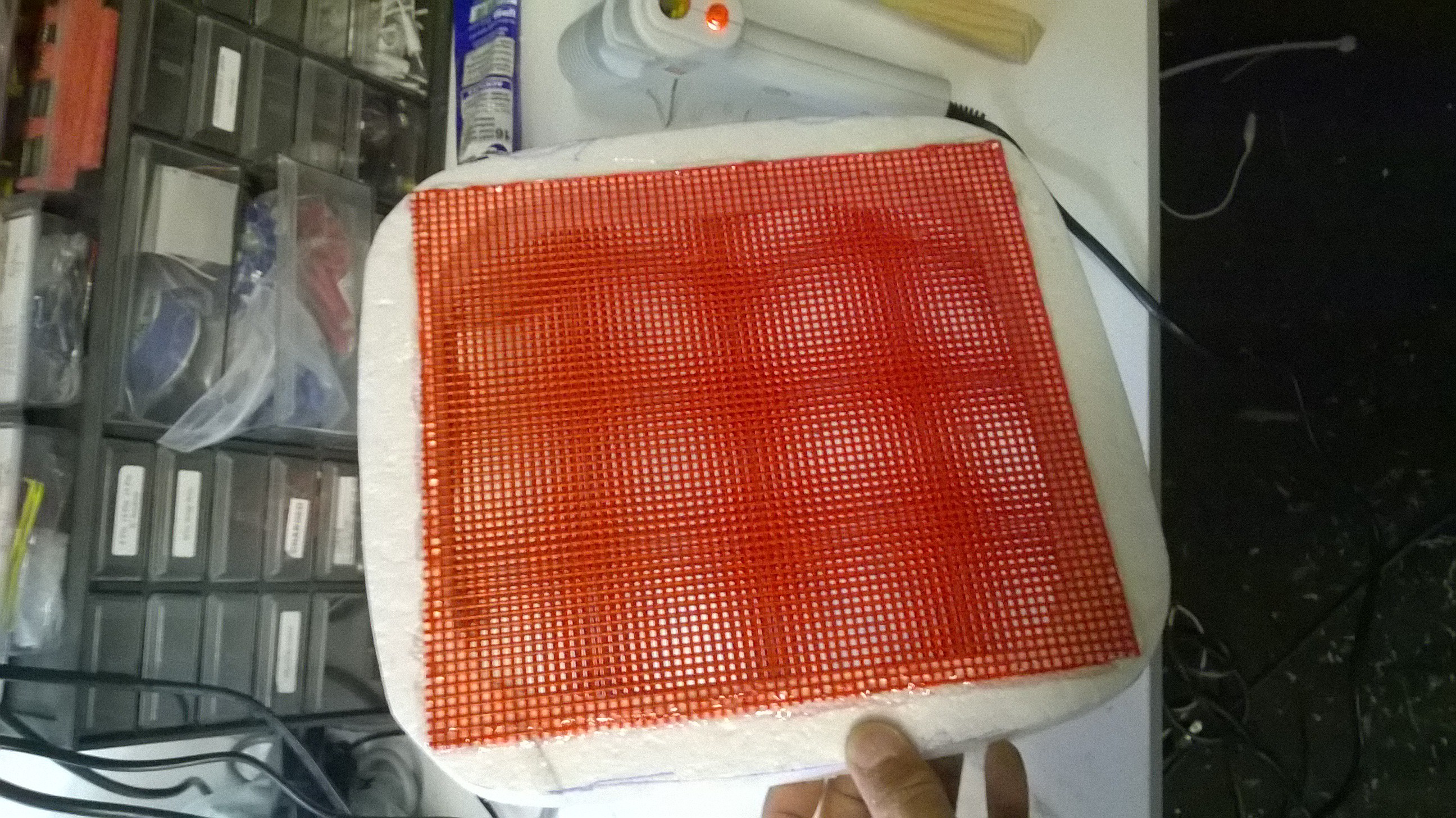
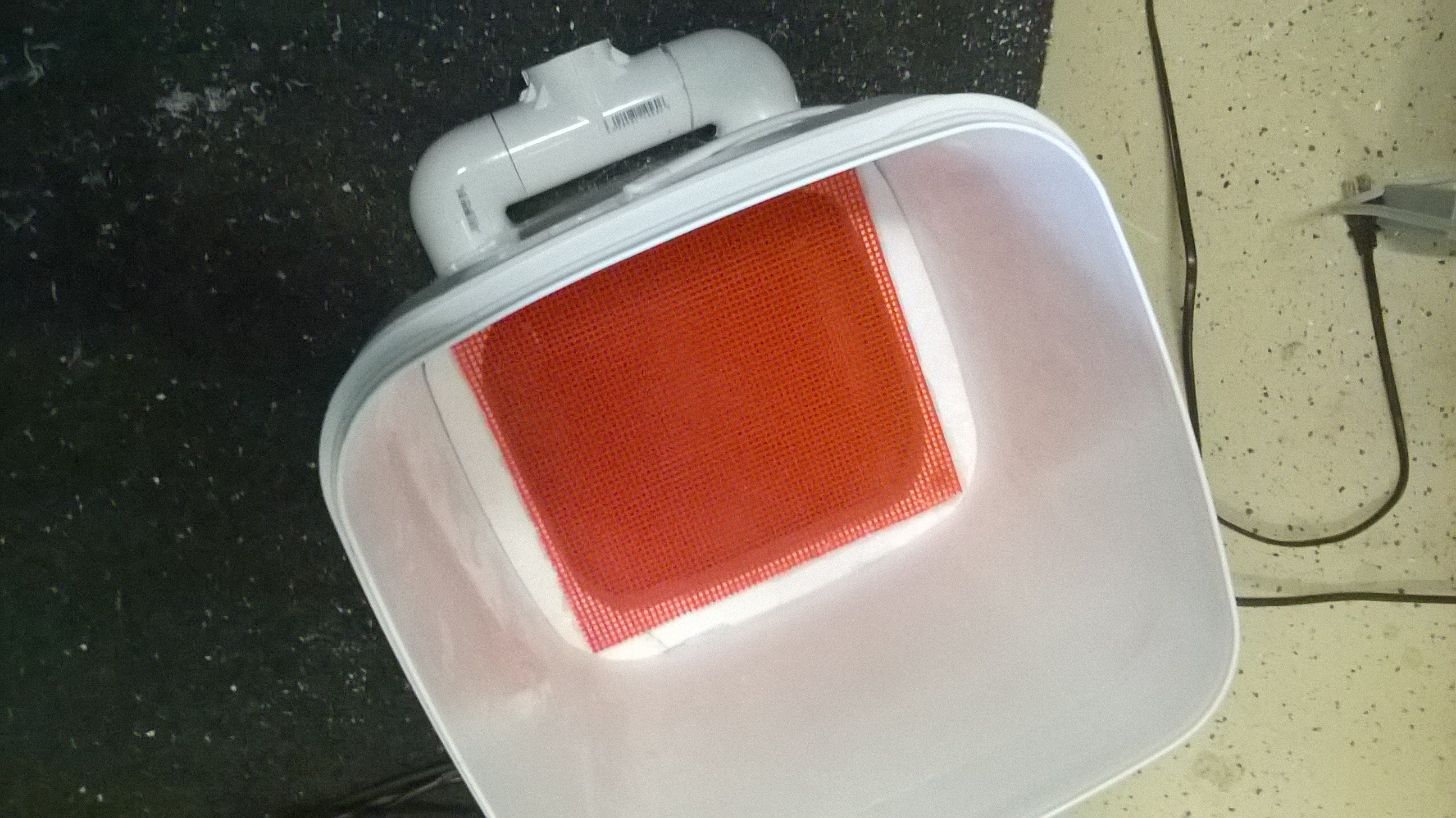
Then a series of grid like baffle was placed on top of the pipes to distribute the air even more. I made this out of a styrofoam frame that was cut out of my styrofoam cooler I found in the dumpster. I then glued some plastic canvas grid sheets onto the top and bottom of the frame.
 This created much more laminar flow
before the air even entered the tubes.
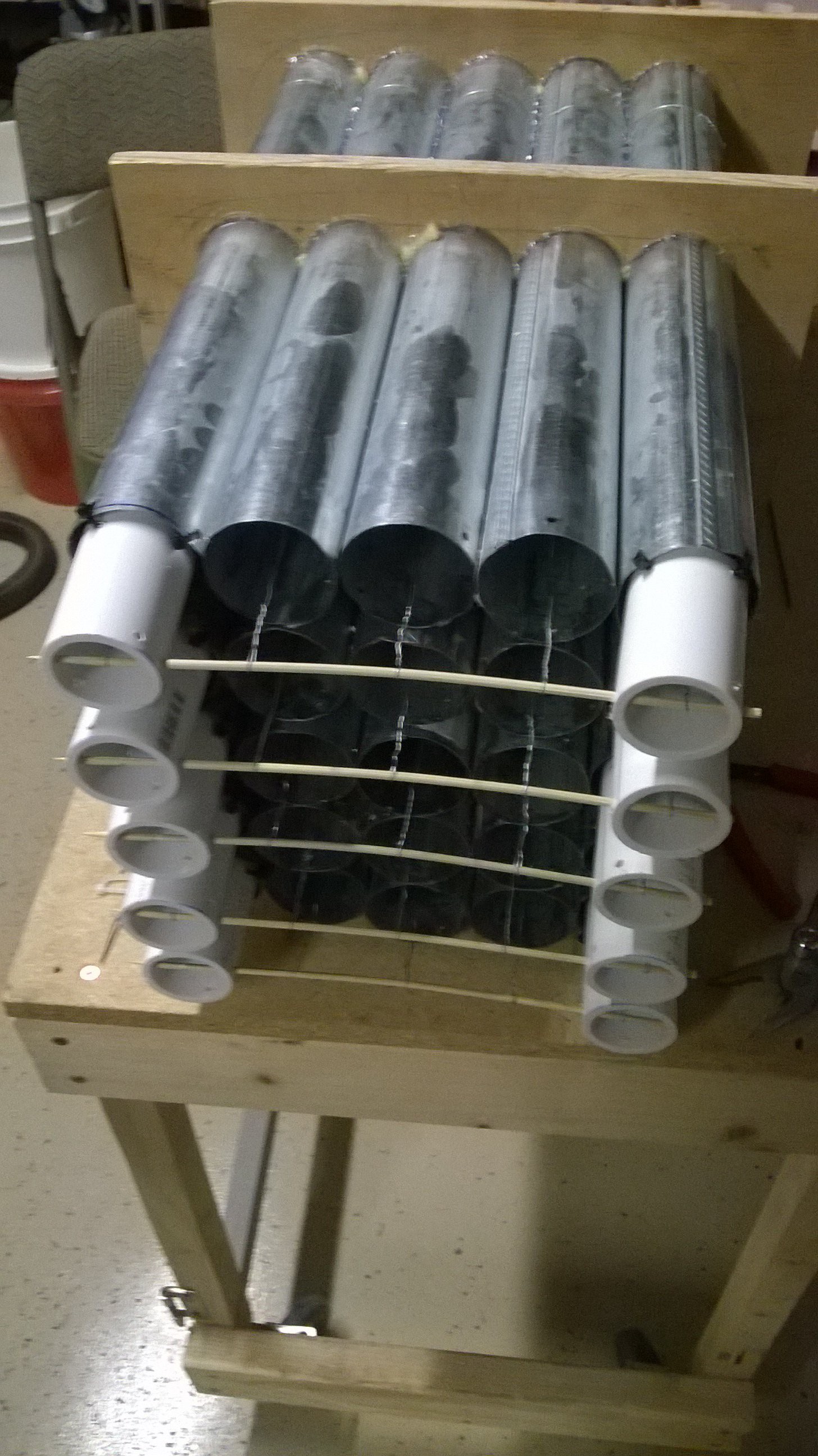
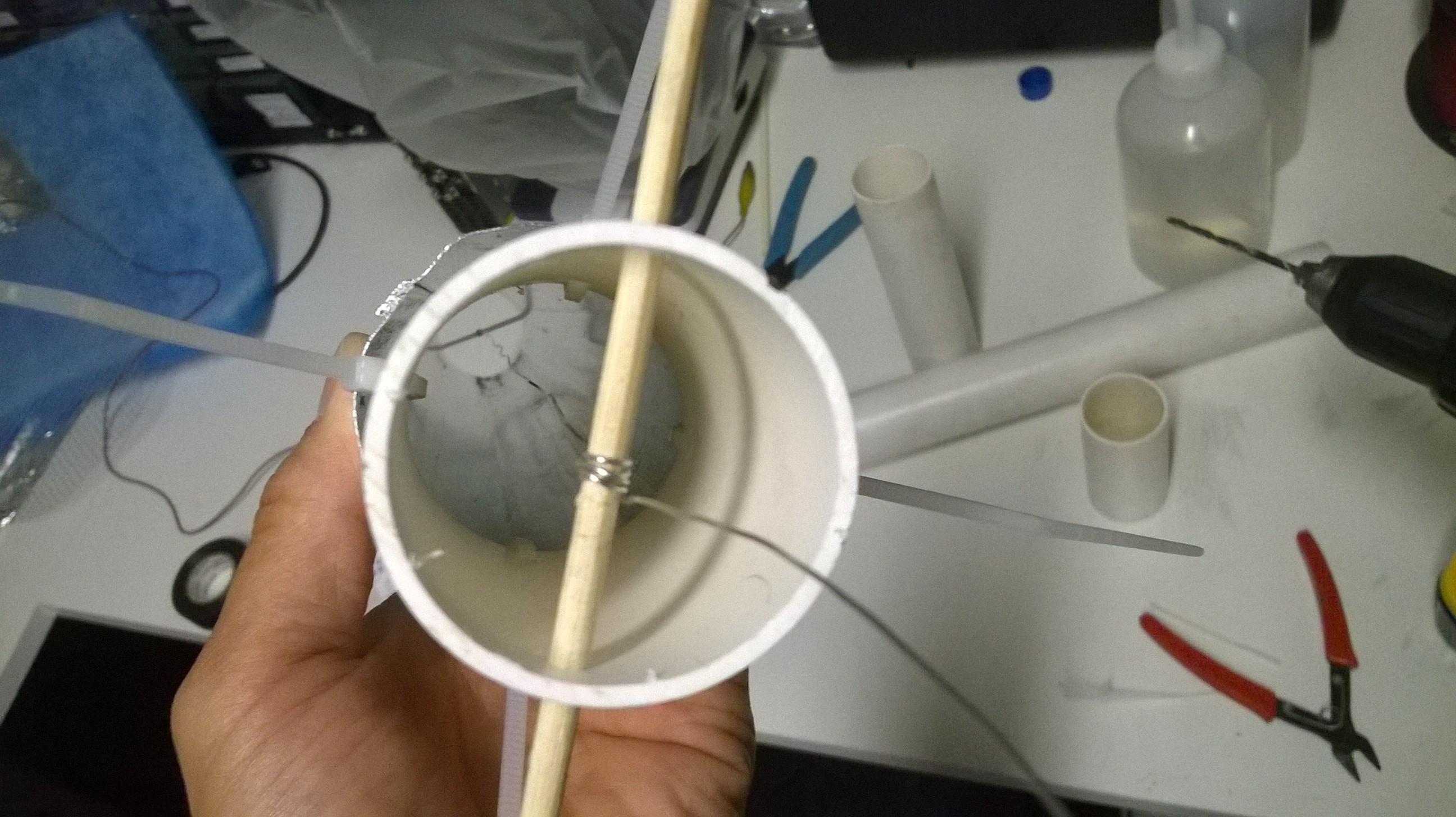
Concerning the shorting problem, I could measure a resistance between the central tube wire and the tube wall and this resistance would be reduced over each test I performed. I had to re-wire the entire back end cutting out all the zip ties which was a pain in the butt. I fixed this problem by adding more PVC pipe sections and suspending the central wire further from the tube walls using shish kabob skewers.
 After rewiring it looked like this.
This would provide considerably more insulation as the electricity would have to travel from the tube wall, through the zip tie, to the length of the pipe and through a stick to get to the central wire. Indeed it worked!
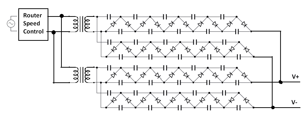
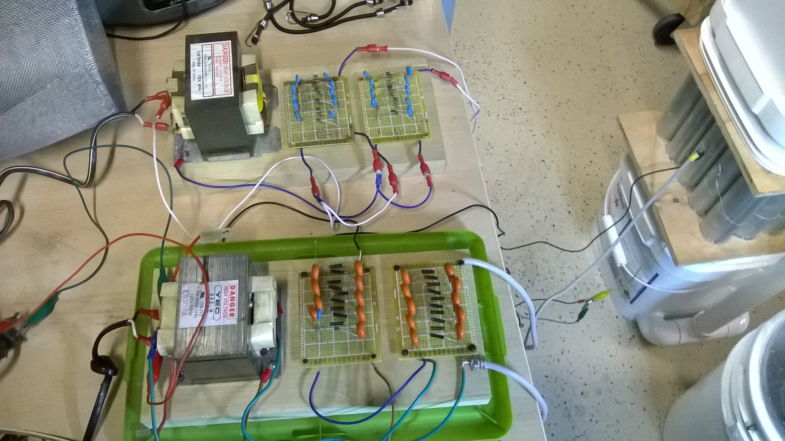
I also noticed that I could pump more energy into the precipitator by running another high voltage circuit in parallel with my existing circuit. This required building another pair of dual polarity cockroft walton multipliers. I ended up using another microwave oven transformer just to keep everything isolated but I believe I simply could have ran the multiplier stages in parallel to the single microwave oven transformer.
I still think I can go to an even higher voltage and current as ESP's want to operate just below the arcing point. Unfortunately my router speed control kept blowing fuses when I attached more stages in parallel.
-
Building the ESP's (Electrostatic Precipitator) Part Two
10/21/2015 at 08:48 • 0 commentsTesting the tube ESP in my jury rigged setup showed promising results. It seemed to filter out almost all of the smoke that the fog machine produced. I then tried it by attaching the vacuum motor to get a higher air flow, I could see a little bit of smoke getting sucked out which was disappointing but it was much less smoke than if the ESP was turned off.
It appeared that 15 pipes was not enough cross sectional area to slow the air down. I would go ahead and make 10 more pipes. Another trip to the hardware store!
At the same time I wanted to prototype the electrified activated carbon idea that I had. I figured an easy way to implement my idea would be to use a stack of flat plastic containers. Each container would have its lid and bottom cut out of it to make a frame, and a screen glued in its place so air can flow through the stack of containers. Then every even container would be filled with activated carbon, and every odd container would contain an ionization grid.
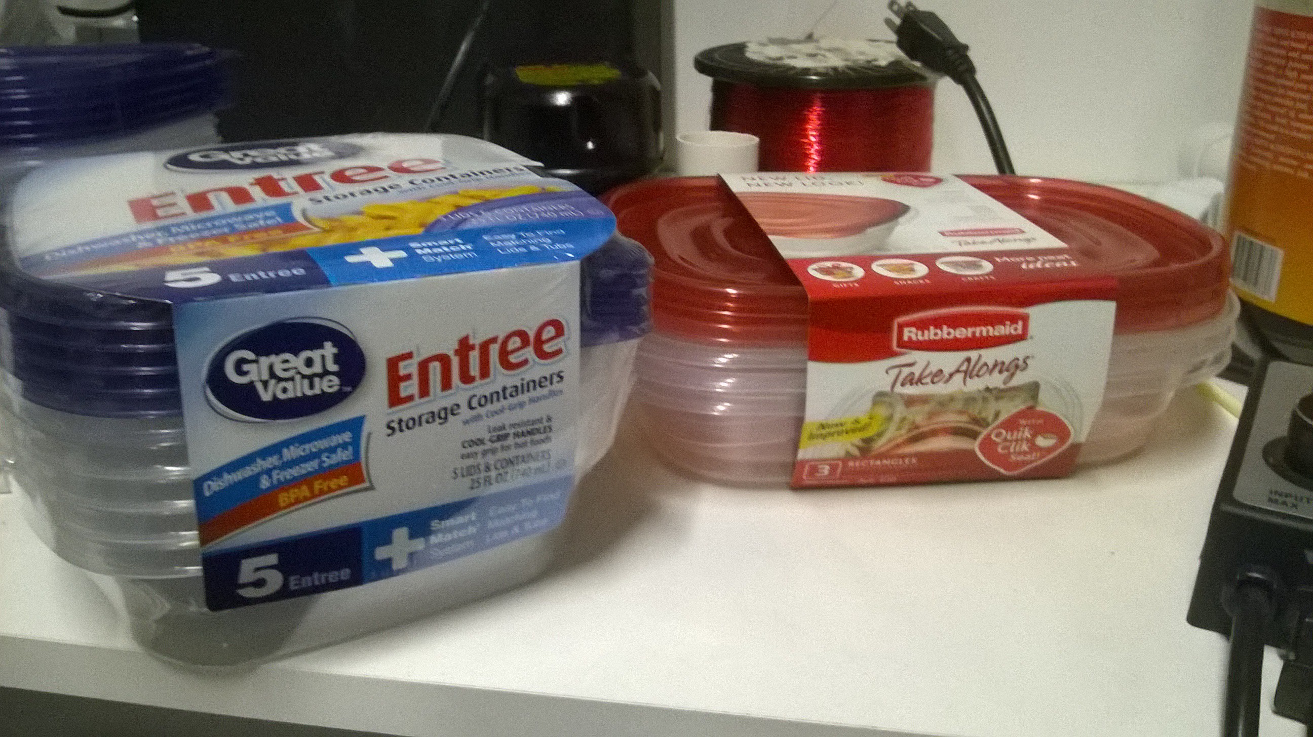
I went to shop for some cheap plastic containers and it seems that plastic sandwich containers would be just the right size not to mention very cheap.
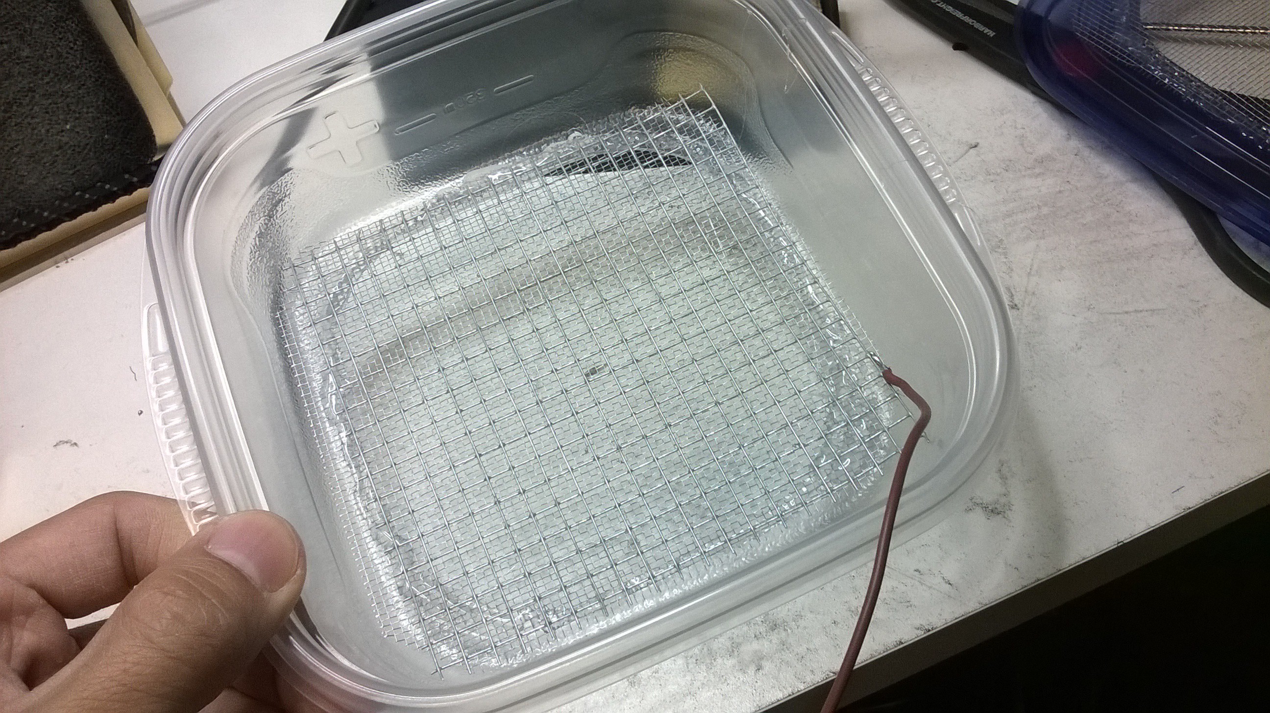
I went ahead to prototype the electrified activated carbon ESP assembly. I cut a square hole in the lids and bottom of all the containers then glued a aluminum screen to it. I then soldered a wire to the screen so I could electrify the activated carbon inside the container.
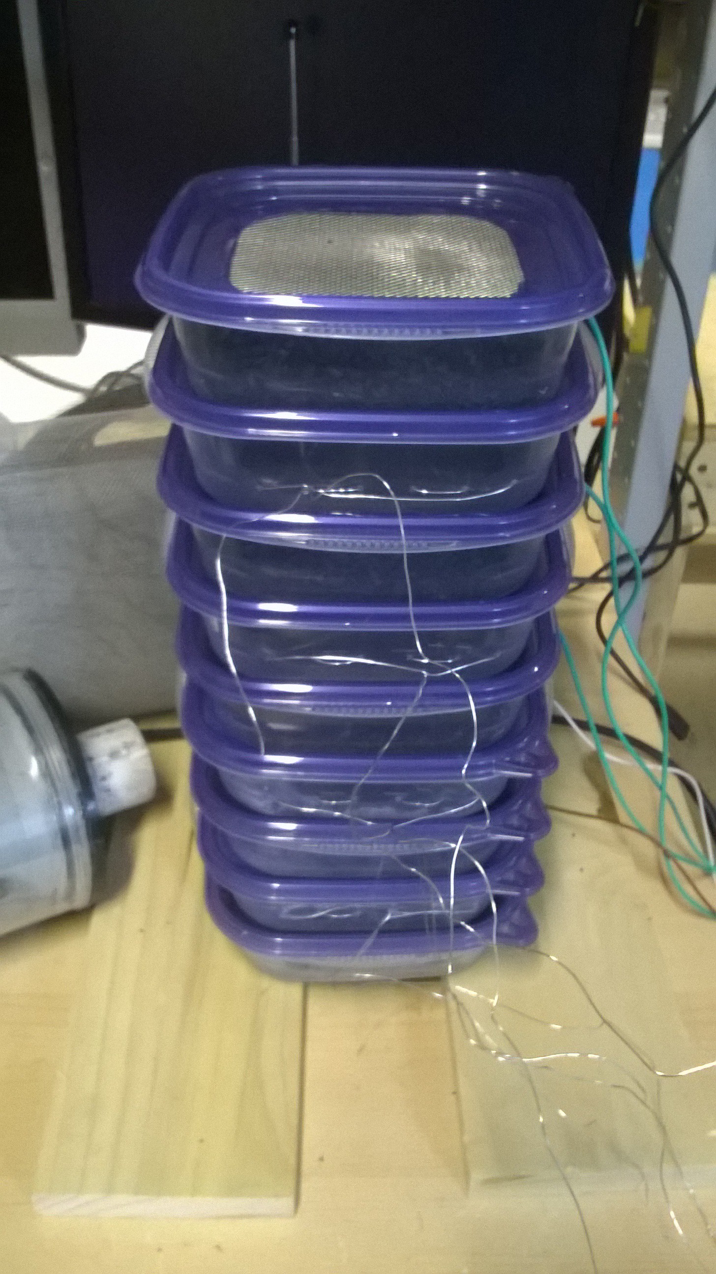
 To make the ionization grid, I simply zig zagged steel wire within the center of the container. With the help of my parents the other containers were all wired in an hour. I then filled the containers with activated carbon and made a stack of them.
 I attempted a small test by placing the vacuum motor on top to suck some fog through it while it was electrified.
 Unfortunately the test was a failure, the air did not have enough time to ionize as it passed axially through all of the containers. The particulate laden air needs a long dwell time to completely ionize so I would have to run more activated carbon containers in parallel rather than in series. This would amount to a lot of activated carbon however. Regardless of the test , I still like the use of sandwich containers to hold the activated carbon as it is highly modular and more or less can be used depending on the application. It also makes it easier to switch out old activated carbon for new.
So far the tube electrostatic precipitator design worked the best so I went ahead and focused all of my efforts on trying to make this design better.
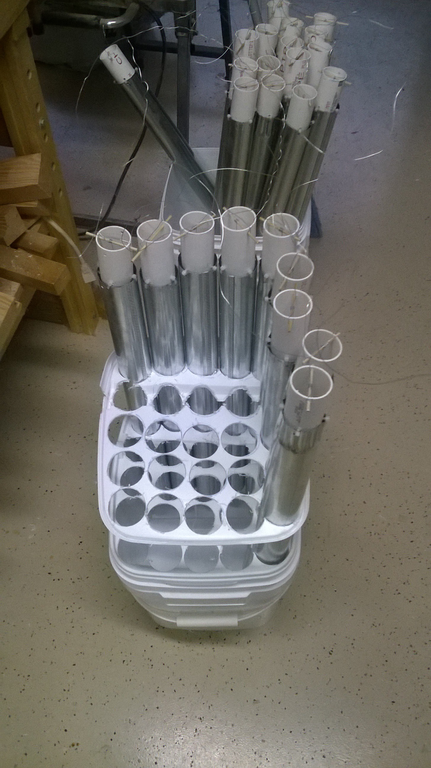
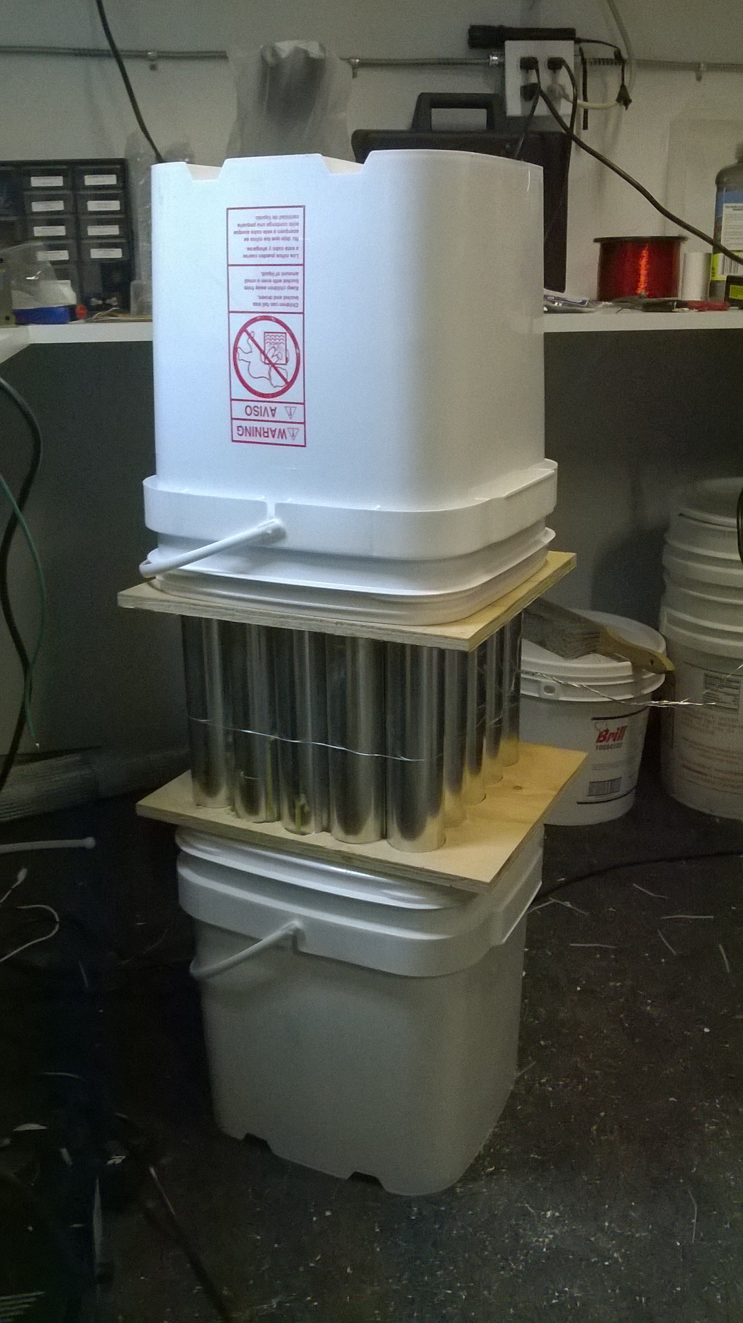
I obtained two square buckets to house the tube ESP inside. With the help of my wonderful parents, I was able to build 10 more ESP pipe assemblies just last weekend. This brought me to a total of 25 pipes. The pipes would be packed together in a 10" by 10" square and fit inside between the two square buckets.
If I were to do this all over, I would have picked square tubes as it was a pain to fill in all the gaps that were present between the round pipes.
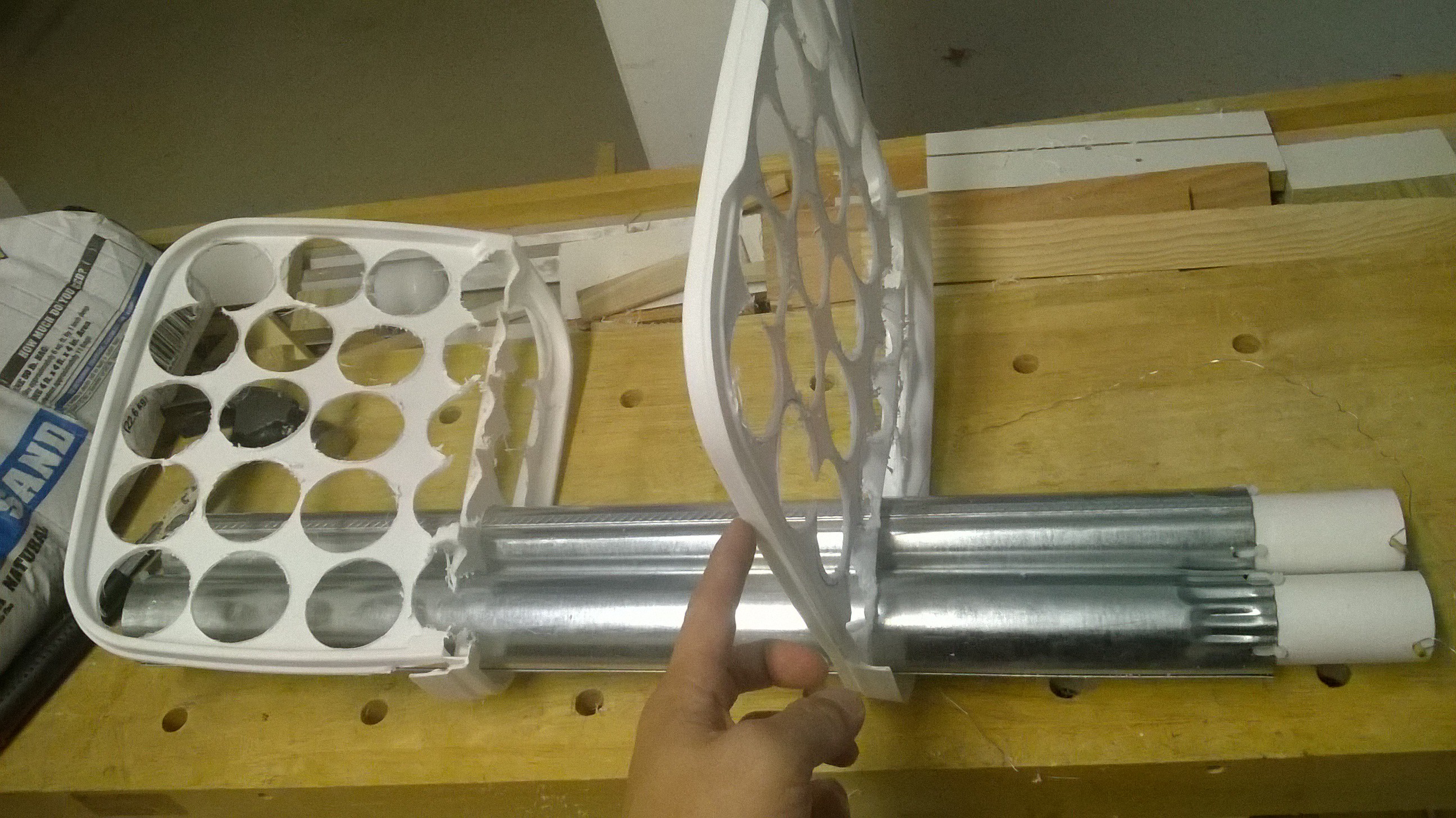
This week has been spent on assembling the ESP and tweaking it. I drilled many holes in the lid of the square bucket to fit the pipes.
This turned out to be a bad method as It turned into a flimsy plastic net after all the holes were drilled.
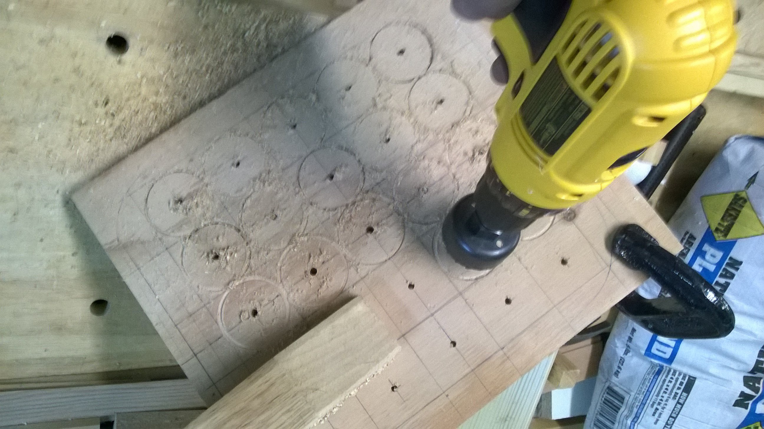
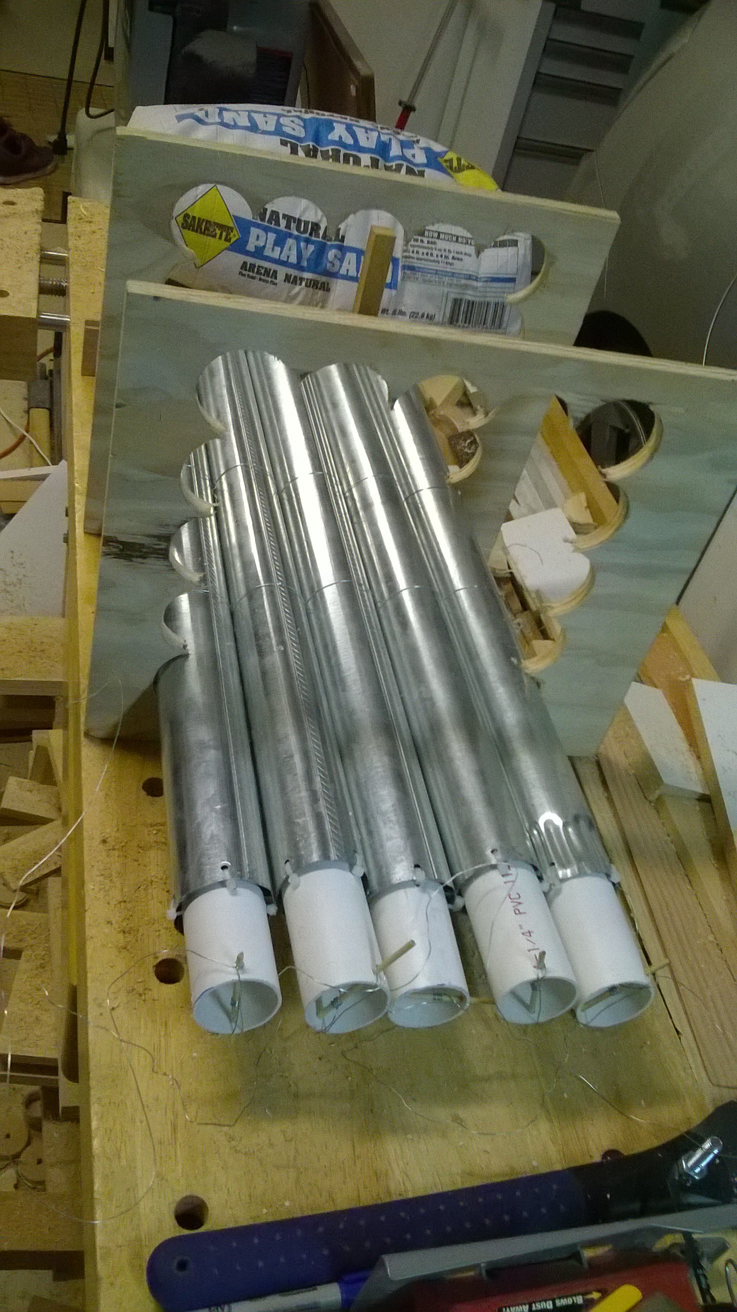
I then turned to a piece of plywood to interface the pipes to the buckets.
This was a lot more rigid and could hold all of the ESP tubes tightly in a bunch. After the holes were drilled I had to insert the pipes.
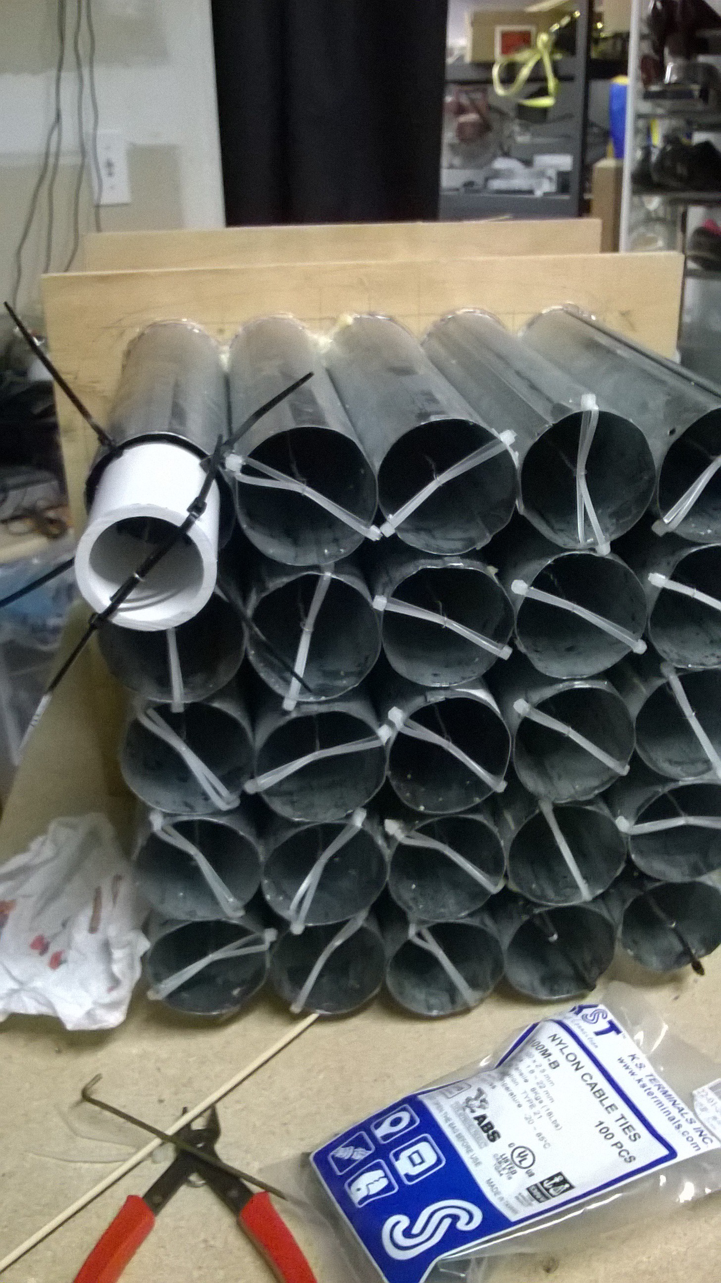
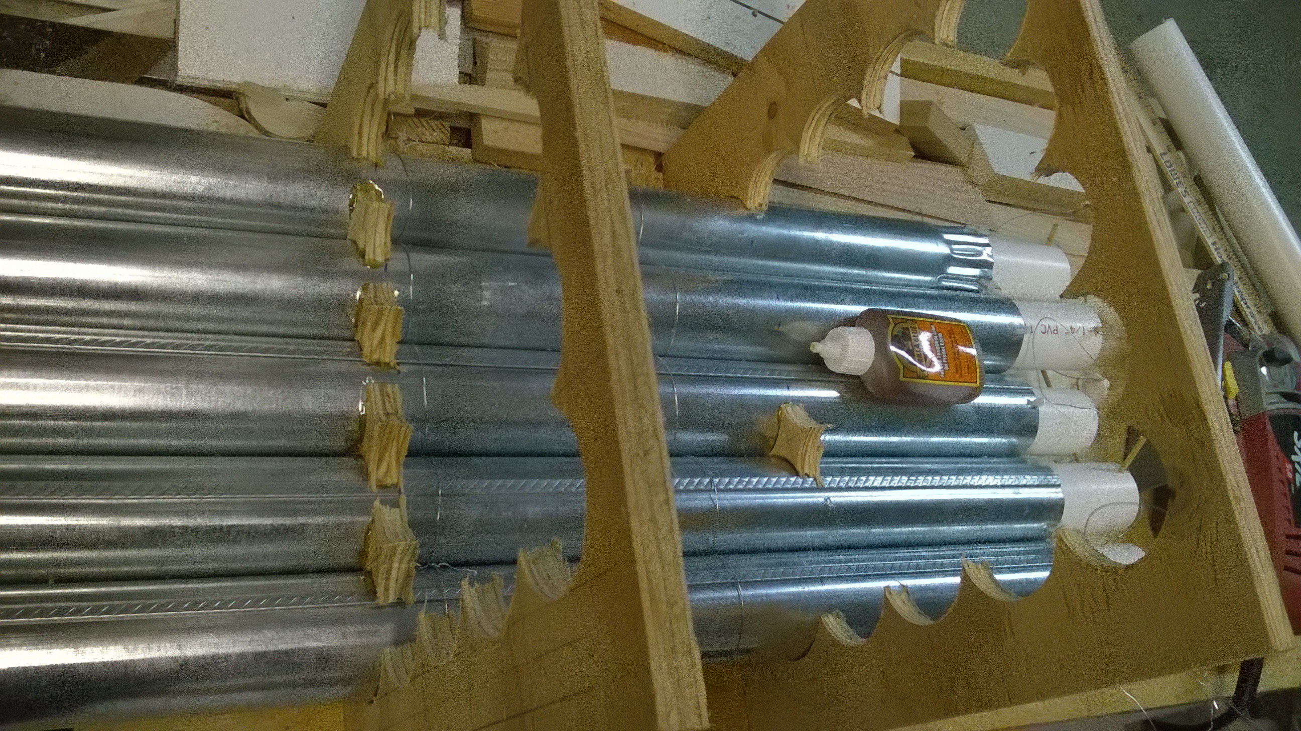
 I then had to fill each gap between the pipes with a star shaped piece of wood and lots of guerrilla glue layer by layer.
 I finally got to the end.
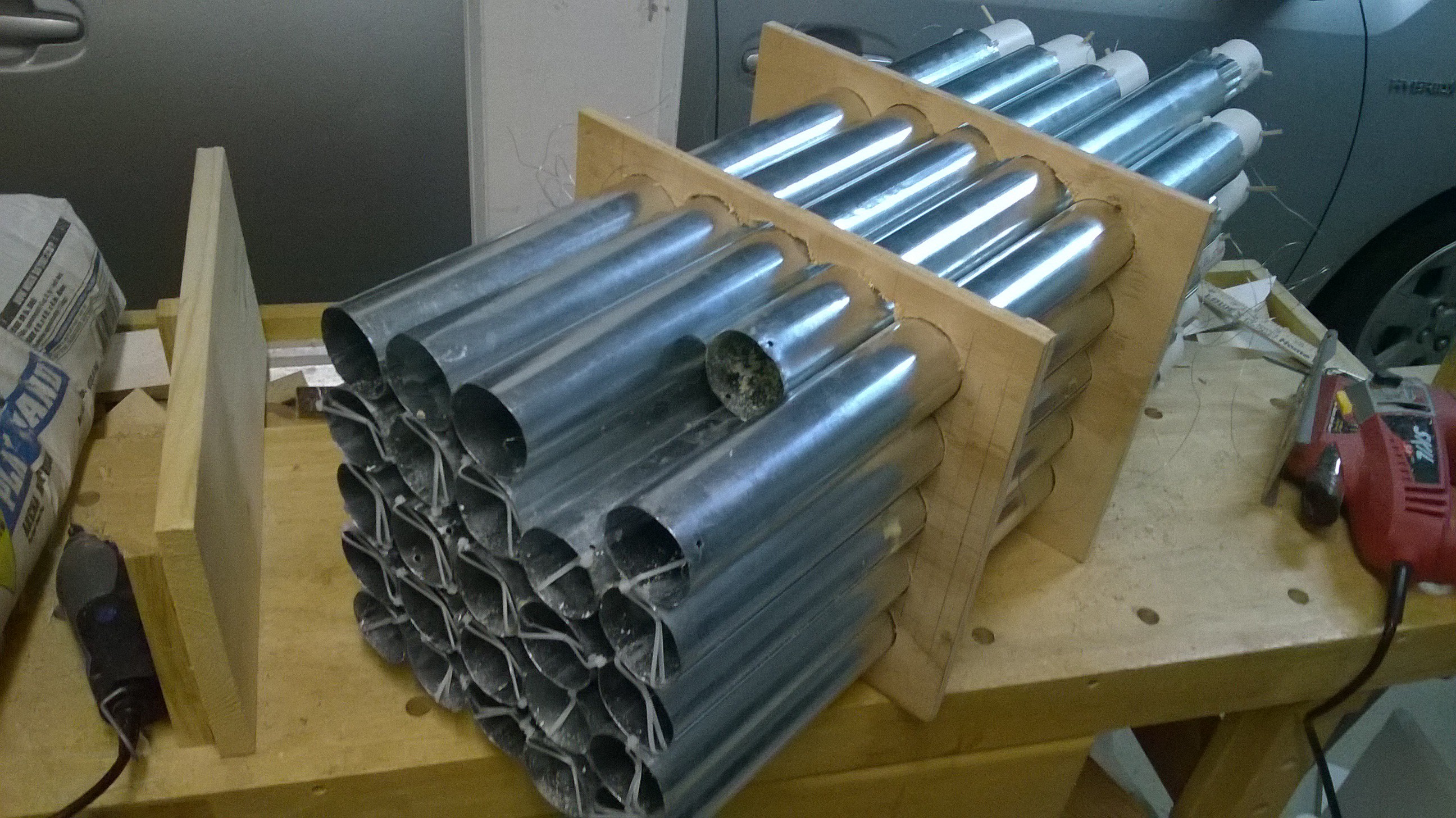
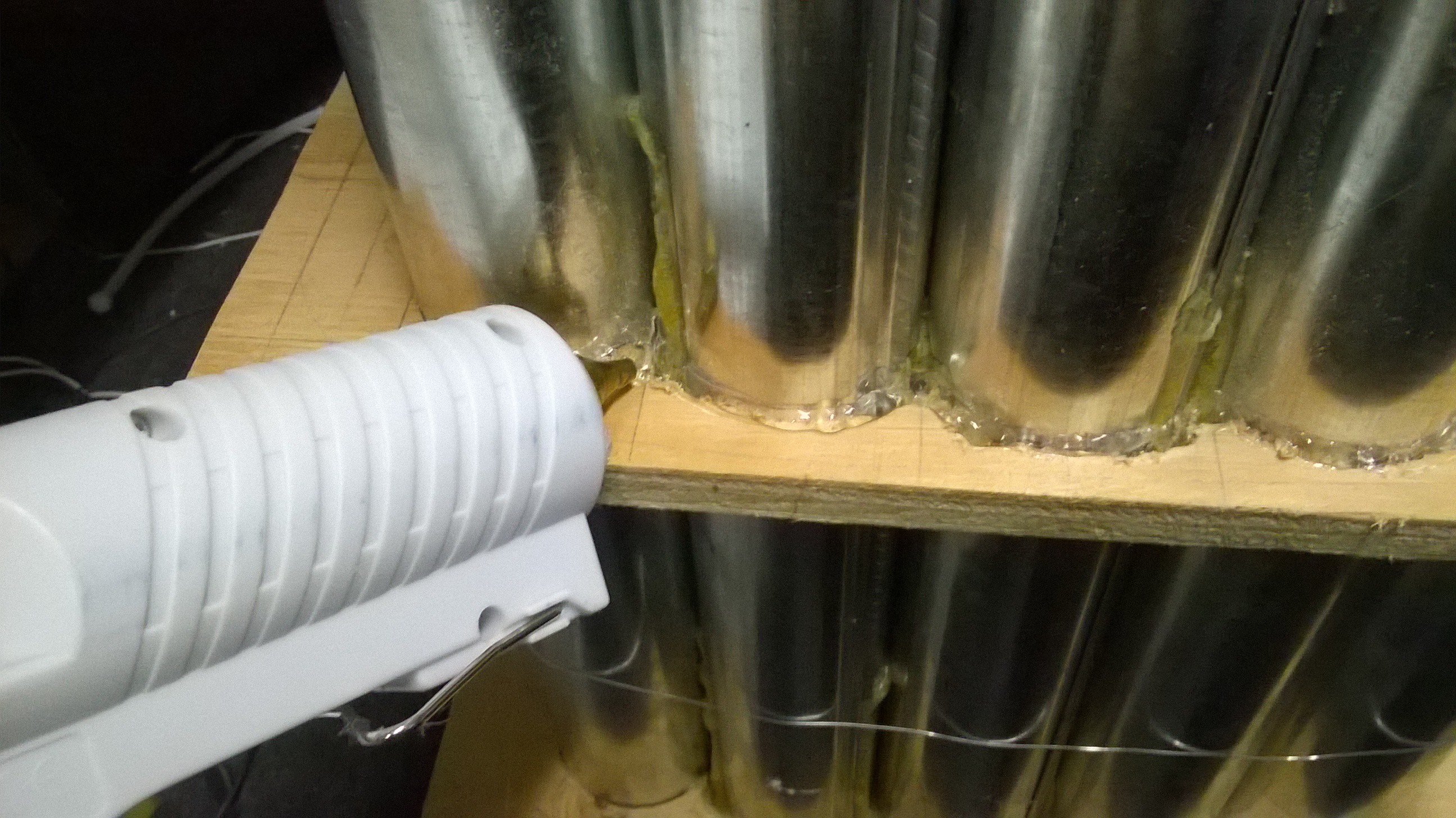
 To be safe, I jammed some foam into the gaps between the pipes and dropped small pools of guerrilla glue in them to make it air tight. I also hot glued the edges to make everything sealed.
 I now had a near finished DIY tube electrostatic precipitator assembly!
Next step is to test this and try and optimize it with the wet scrubber and activated carbon assemblies.
-
Building the ESP's (Electrostatic Precipitator) Part One
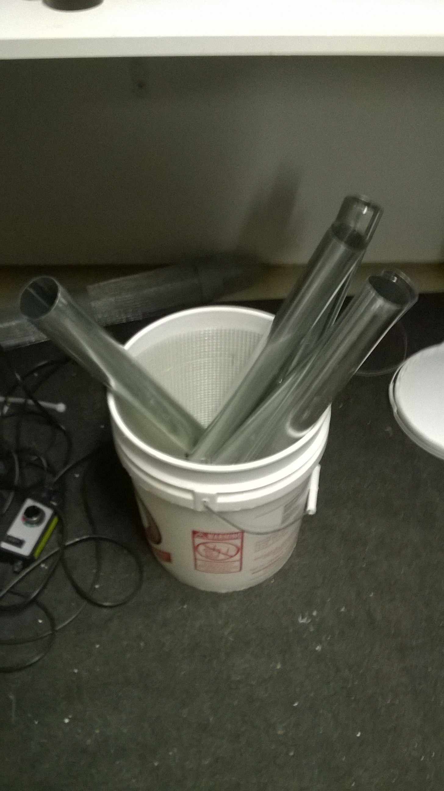
10/20/2015 at 09:39 • 0 commentsTwo weekends ago I prototyped a test rig of my tube ESP (electrostatic precipitator) device. I first cut three of the 10ft length galvanized metal downspouts in to 2ft sections.
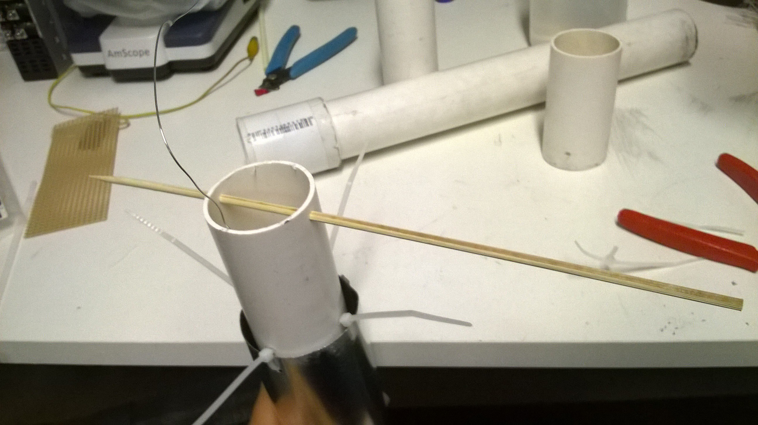
To create a support structure for the wire that would run through the center of the pipes, I cut a 3" section of PVC pipe and zip tied it to the end of the metal pipe section.
Then, using a shishkabob stick, I ran it through the PVC pipe and wrapped the wire around the stick so it can be tightened by spinning the stick, tightened much like a guitar string.
On the other end I used a zip tie to suspend the wire in the center of the pipe.
I did this 15 times and ended up with a bunch of pipe assemblies.
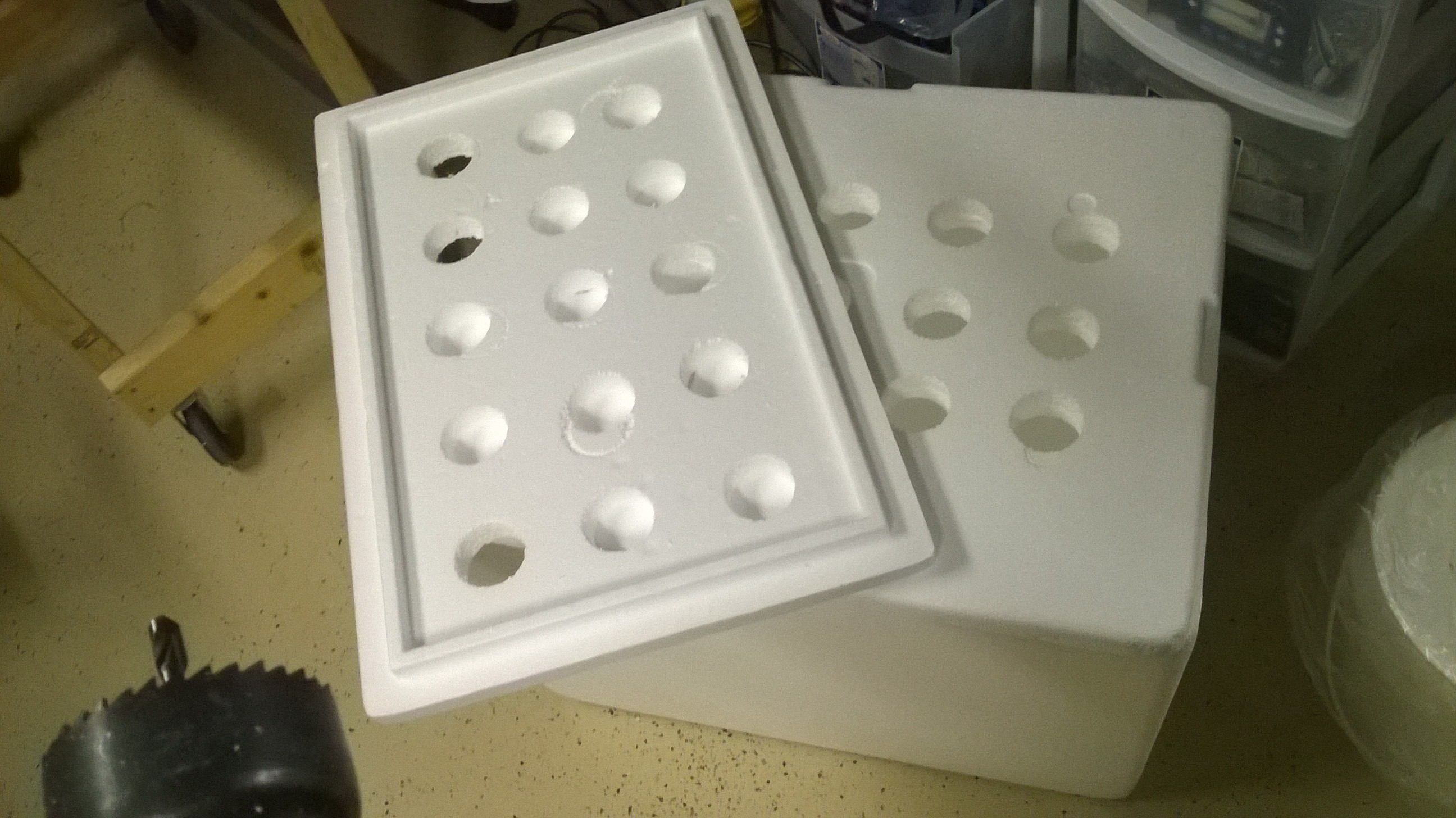
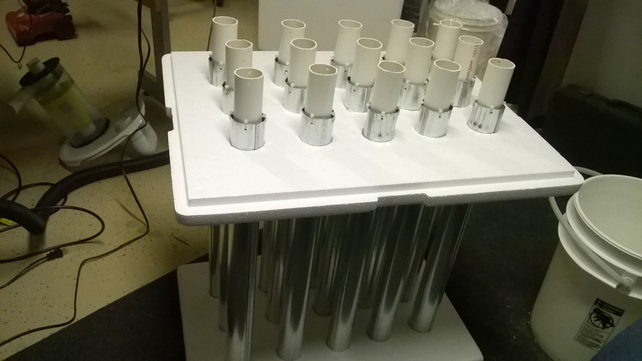
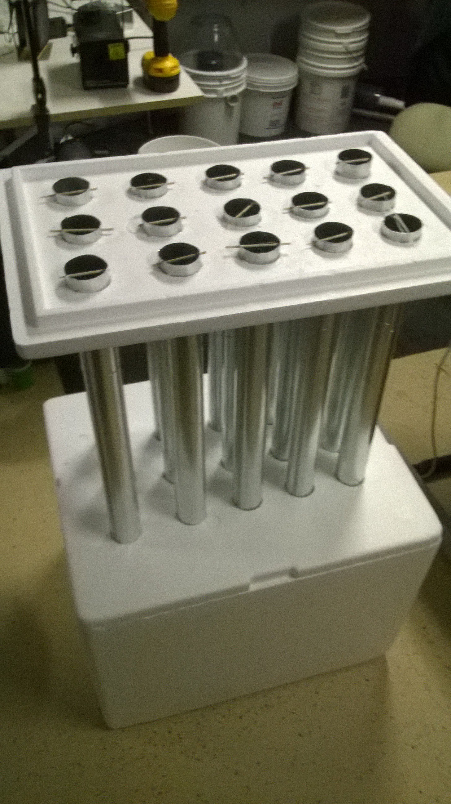
To test the 2ft sections of pipes, I took two Styrofoam coolers I found in the dumpster and drilled holes in them. Since this was only a test, I spaced the holes far apart so an ESP can be assembled easily. In the actual version I would placed the pipes as close together as possible.
I inserted all of the assembled pipes into the holes.
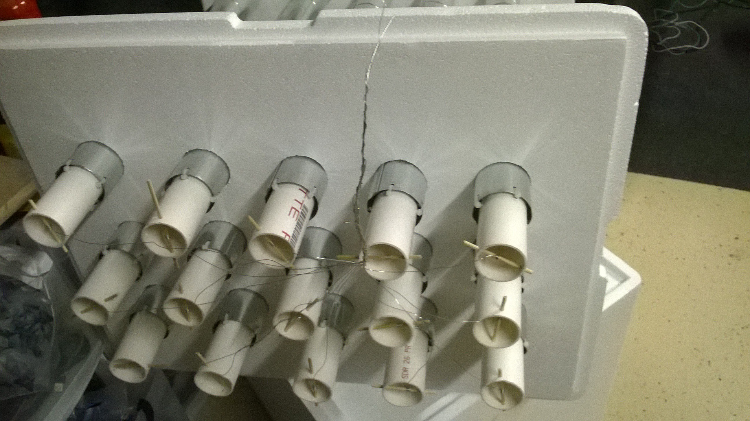
 I then wired all of the pipes together
I then drilled a hole in the bottom cooler so my fog machine can shoot into it.
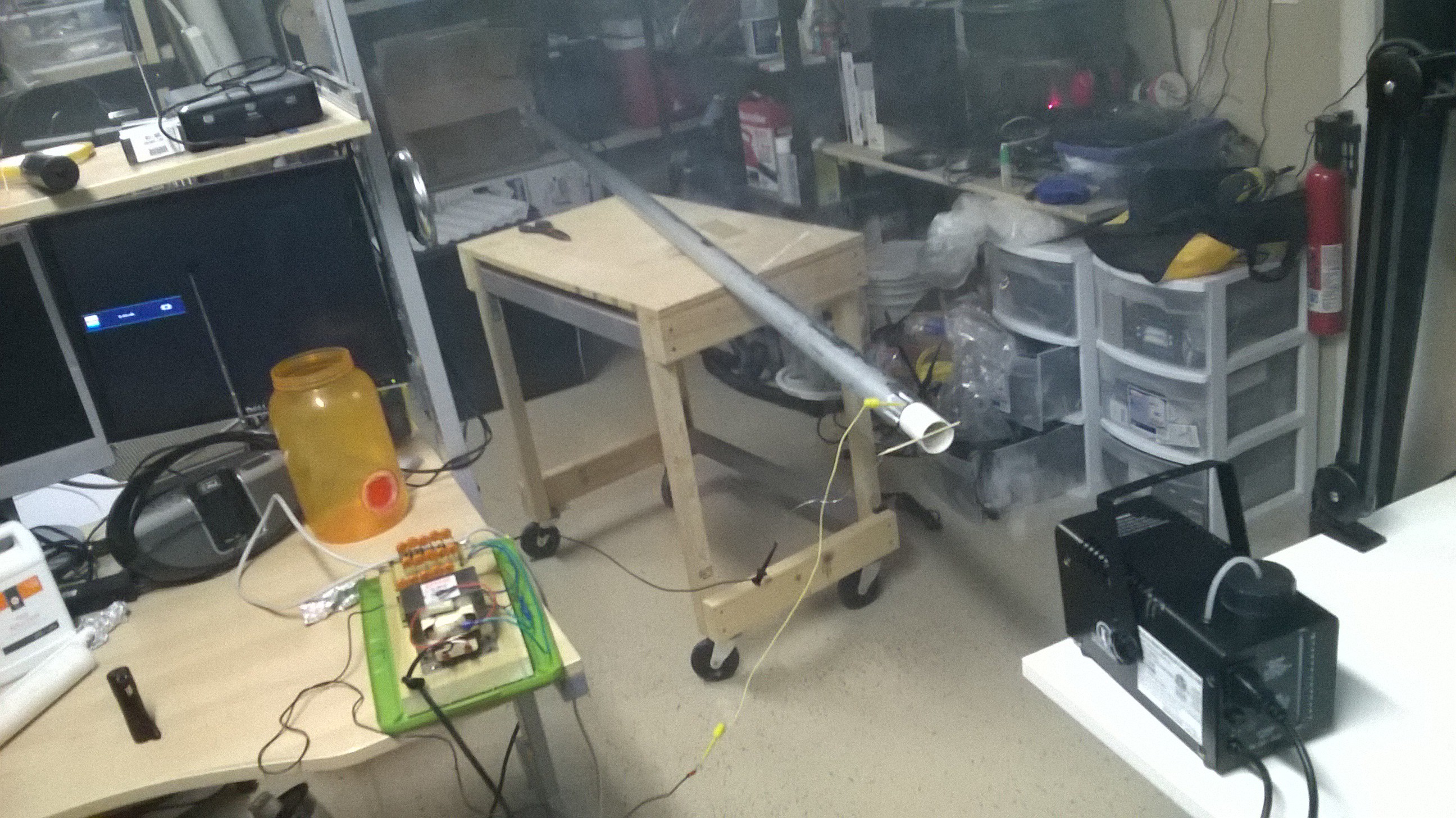
Here is a video of an early test. -
My Two DIY Electro-Static Precipitator (ESP) Designs
10/20/2015 at 08:56 • 1 commentTube ESP
As I yet again went back to the drawing board, I decided I would pursue a tried and true method in designing an electrostatic precipitator to deal with the sub micron particles along with any new design I'd come up with just in case the new idea didn't work as planned.
For my ionizing circuit, I was going to build a tube electrostatic precipitator that would either go before or after the wet scrubber as a separate stage. A tube electrostatic precipitator has a thin wire going axially through the center of a tube that is held at high voltage to produce corona that ionizes the air. Particulate laden air is passed through the tube and ionizes the particles such that it sticks to the walls of the tube.
Although I intended to do this originally but was stopped by the fact that these devices produce Ozone, I would make the design such that it would minimize Ozone production by using positive corona and then absorb any produced Ozone into the scrubbing liquid as well as the activated carbon stage at the end. The Ozone absorbed into the scrubbing liquid will help sterilize it and help oxidize any VOC's that enter it, the remainder of the Ozone should be absorbed by the activated carbon stage.
I purchased several round galvanized gutter downspout pipes from the hardware store and some steel wire. I rigged one of the pipes to run a single steel wire along the center of it and connected it to my high voltage circuit. As the pipe was energized, I shot the fog machine into one end. NO SMOKE CAME OUT THE OTHER END! As I turned the high voltage electricity off, the smoke started to pass through pipe. It was like magic! At last, I had a device that worked for sub micron particles!
Now it was time to cut up the pipe into sections so I can fit it into a housing. I used a general guideline that there needed to be 200-800 ft^2 of collection surface per 1000acfm. I approximated that my vacuum motor is providing roughly 100cfm. If I cut the 2inch diameter 10ft length pipes into five 2ft lengths, I could use five pipes go give me 25 pipes total with one pipe section giving me a little over 1 sq ft each. The total square footage of the collection surface being about 25ft^2 for 25 pipes. Electrostatic precipitators are quite bulky!
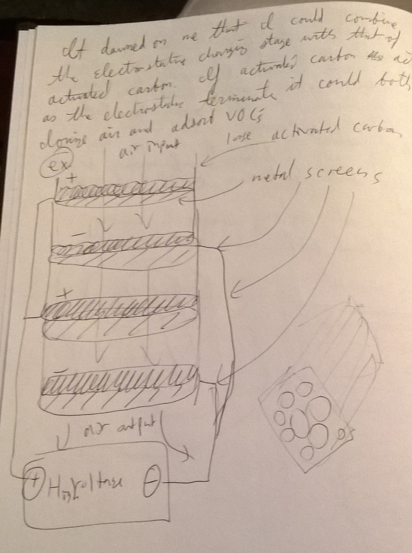
Electrified Activated Carbon ESP
As I thought to figure out how to incorporate the activated carbon stage as well as shrink this device, a new design came to me. I could combine the activated carbon stage and the electrostatic precipitator stage into one. Since activated carbon naturally has a large surface area, why not electrify it and use this as the electrostatic precipitator? My idea was to have sectional containers of activated carbon that is charged to a high voltage seperated by a small distance from which in between the carbon sections are ionizing grids charged to an opposite polarity to provide corona and ionization. As particulate laden air passes through the ionizing grids, the particles should adhere to the electrified activated carbon which acts as a collection surface for both particulates and VOC's (including any Ozone produced). I thought to prototype this new electrified activated carbon design in addition to prototyping the tube electrostatic precipitator as I know at least this idea works reliably. Should one implementation fail, I could rely on the tried and true method. -
Testing With Sub Micron Particles (Smoke)
10/20/2015 at 08:21 • 1 commentThank you HAD for allowing me to be in the finals! Truly a shock, a thrill, and an honor. Ever since the announcement I have been non-stop working to continue the development and testing where I left off on the last video. I only bit of time to write some project logs as I'm waiting for glue to dry.
From where I left off... The first order of business was testing the two stage wet scrubber design with a large source of sub-micron particles. I'd like to thank the HAD community and my friends for providing me many great ideas on how to test my machine cheaply and how to detect sub micron particles --namely the use of smoke detectors as a cheap particle detector was simply brilliant.
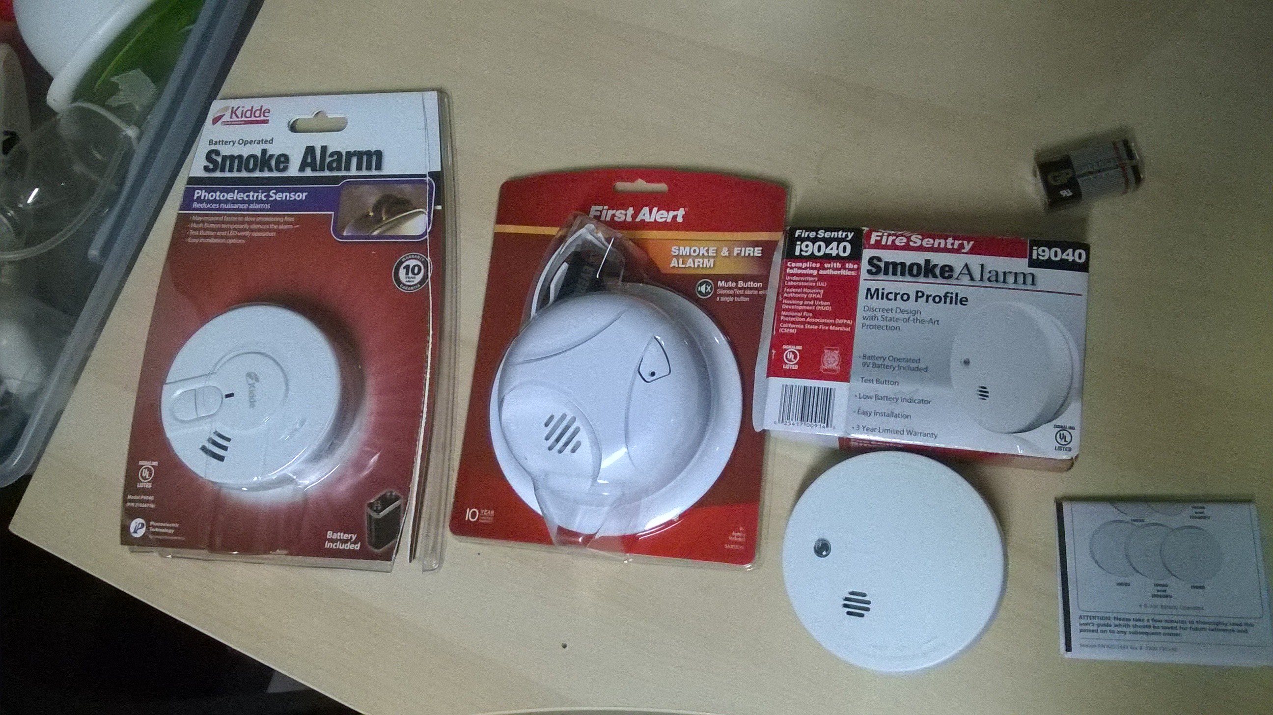
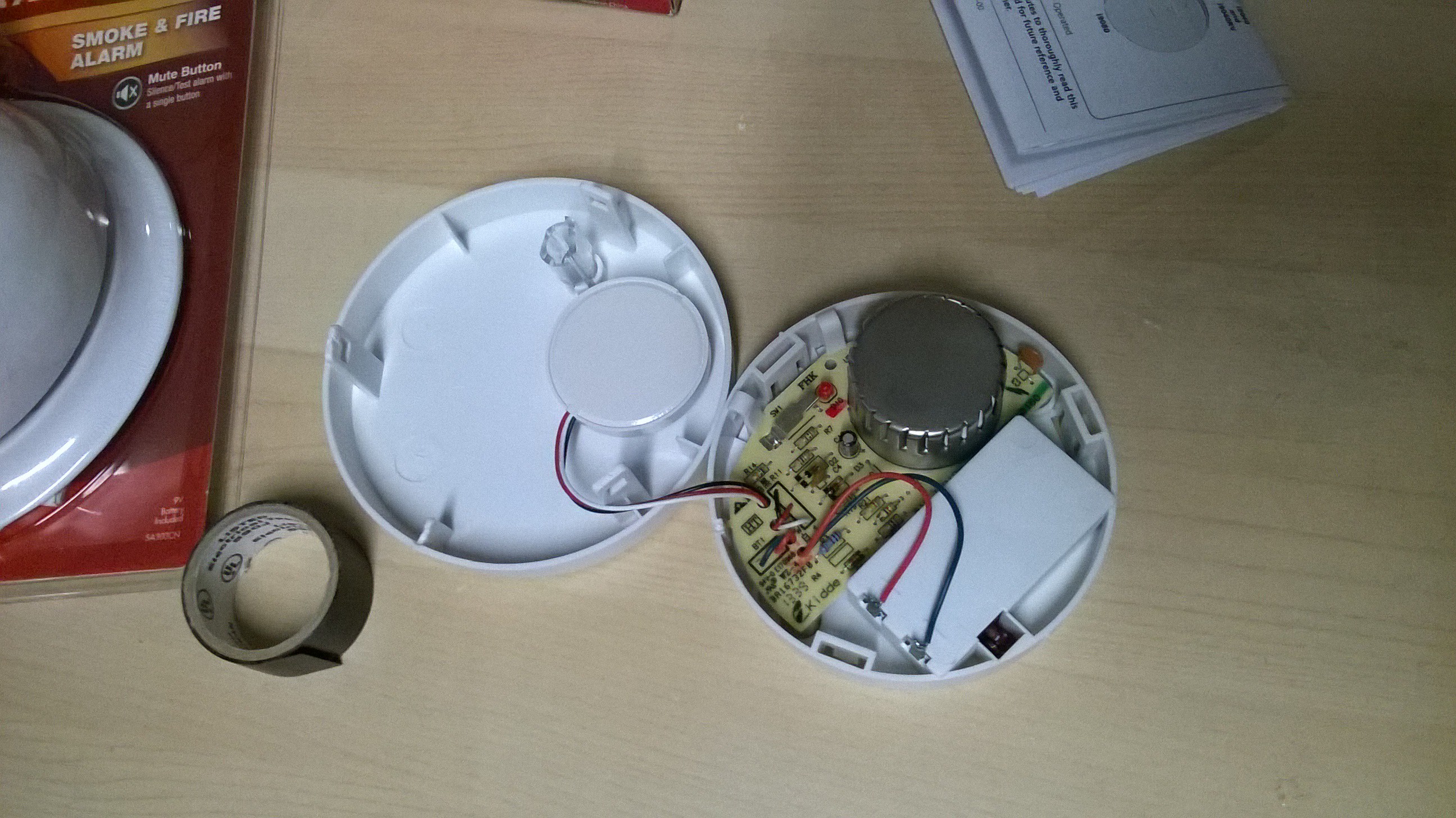
The first thing I bought were three smoke detectors two ionizing type and one photoelectric type. They were very cheap!
My original intent was to probe inside to get a voltage reading from the photo or ionizing particle detectors but I soon found this was unnecessary.
I needed to find a source of sub micron particles to test my machine that wasn't too dangerous. My friend suggested I use nano powder zinc dioxide that could be sourced online to make DIY sun creen but the thought of shooting nano-powder everywhere didn't seem safe at all --even with a resperator.
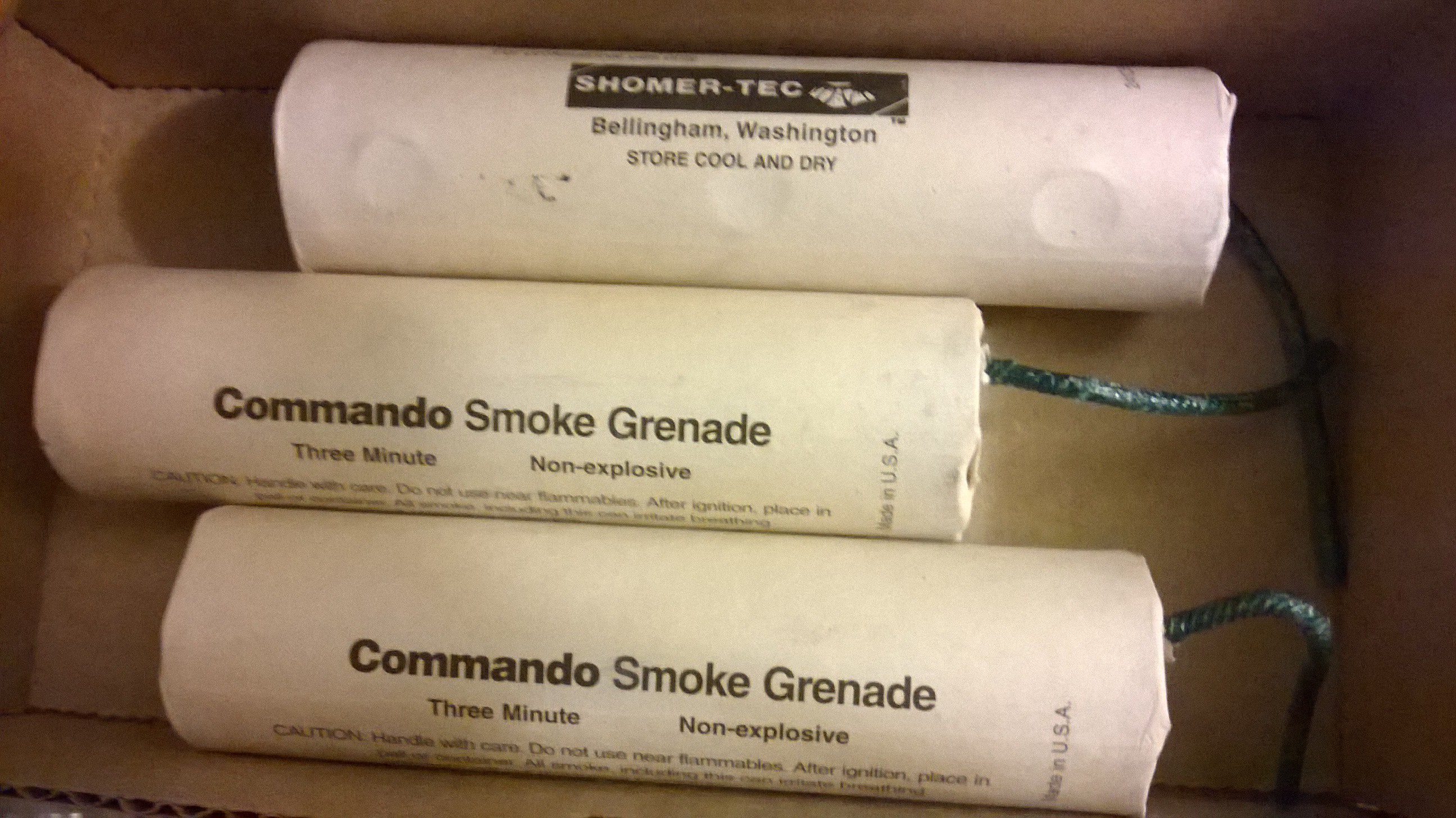
Another friend gave me three commando smoke grenades to test my machine with!
This is an all or nothing kind of test! I was going to save these babies when I got my machine finally working because if I set this off in my garage and the filter didn't work, I'd have a lot of explaining to do to my wife and neighbors... and fire department.
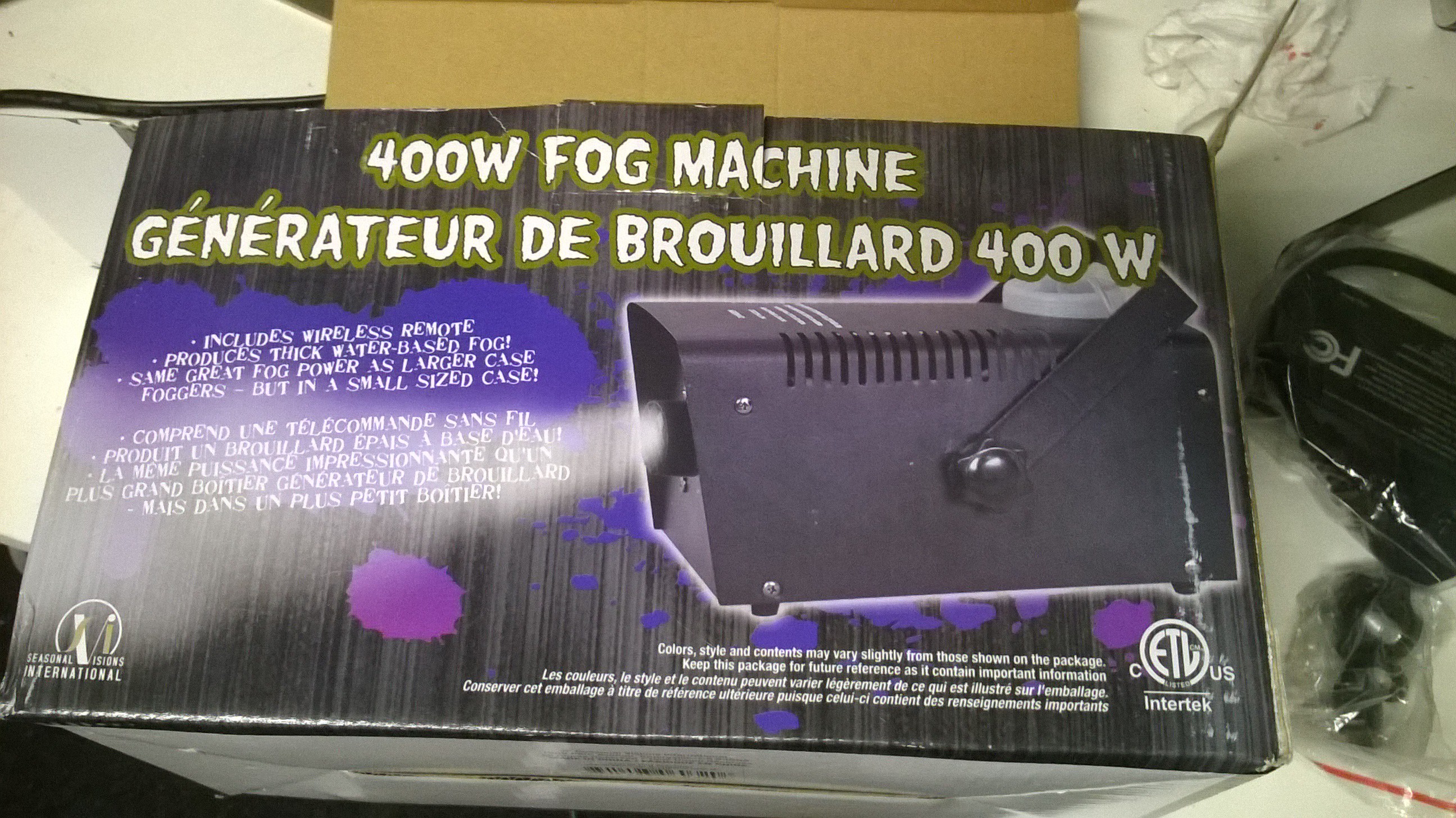
Luckily as I was walking through the department store, a Halloween store opened up. Then something clicked with me. I can use a fog machine!
Fog machines produce a huge quantity of sub micron particles (smoke) and it is also safe to use and breath. I bought a fog machine and quickly went home to test my machine.
I filled the fog machine with fog juice, let it warm up, then shot it directly into the input of my two stage wet scrubber. What happened next was, well, exciting.
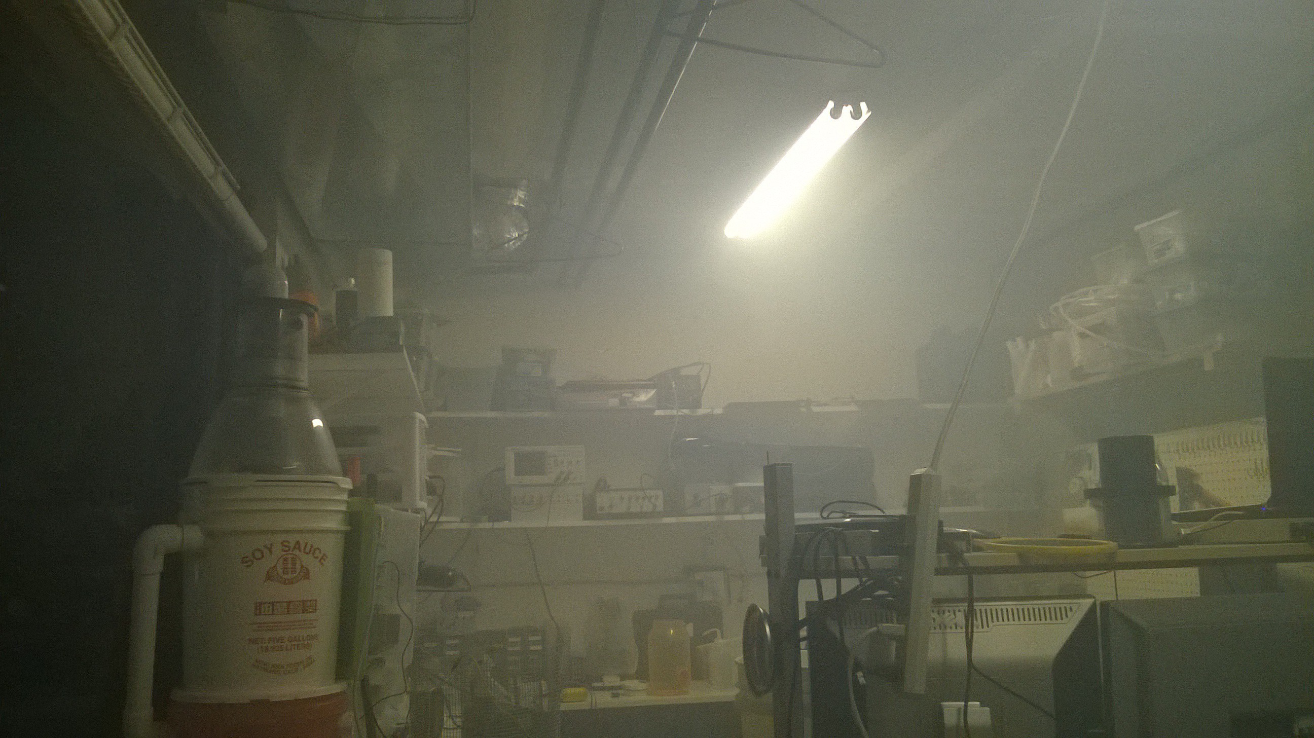
 Not only did my wet scrubber did basically nothing to filter any of the smoke, it filled my entire lab with smoke and set off all the smoke detectors that I just bought all at once including the one built into my lab. I ran around frantically trying to turn off all the smoke detectors. As I opened my garage, a huge smoke cloud went outside. Luckily none of my neighbors noticed.
So it appears that the electrospray ionization effect wasn't nearly as great enough as I expected. I was quite sad that this did not work as I planned. I realized the scale and implementation was a bit off. I needed much more surface area and a lot more corona to sufficiently ionize the particulate laden air.
-
Artist Rendition of "Productized" Designed Look/Feel of Project
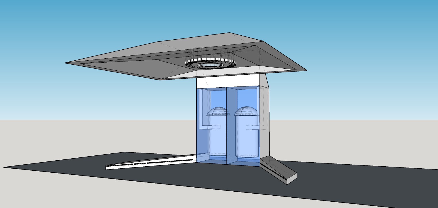
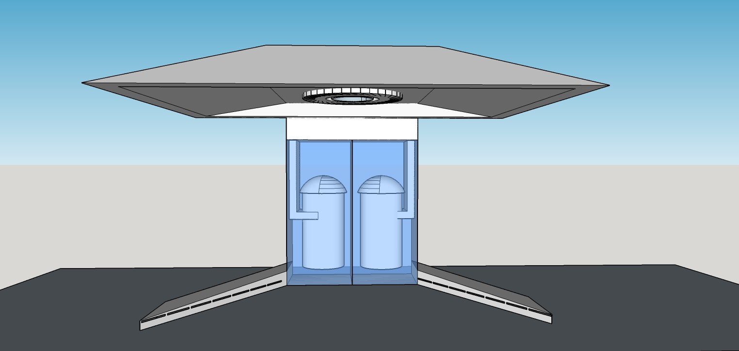
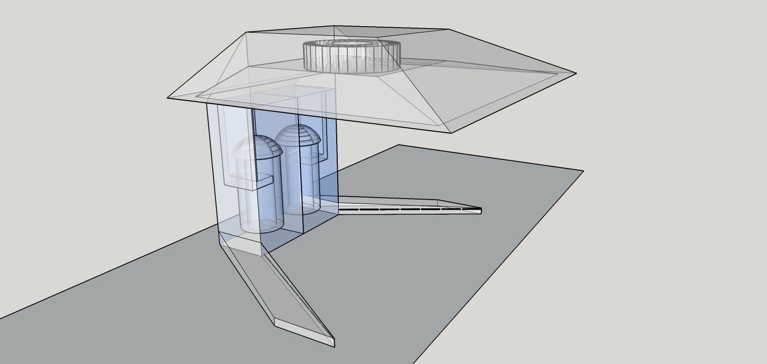
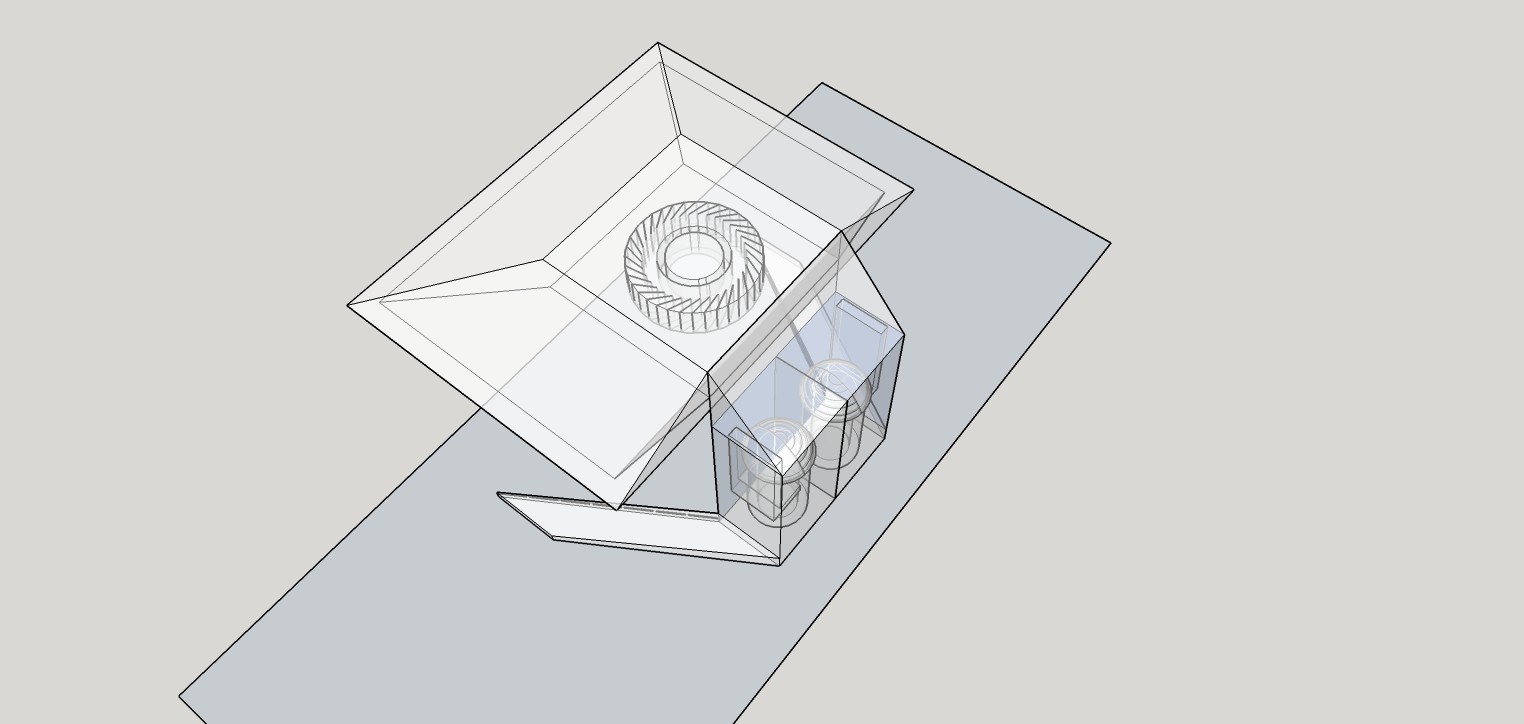
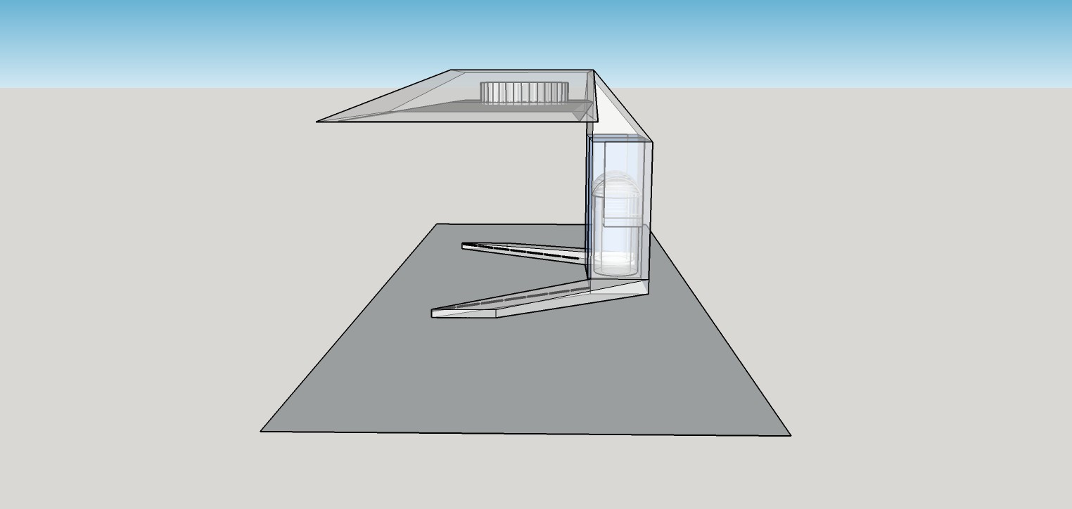
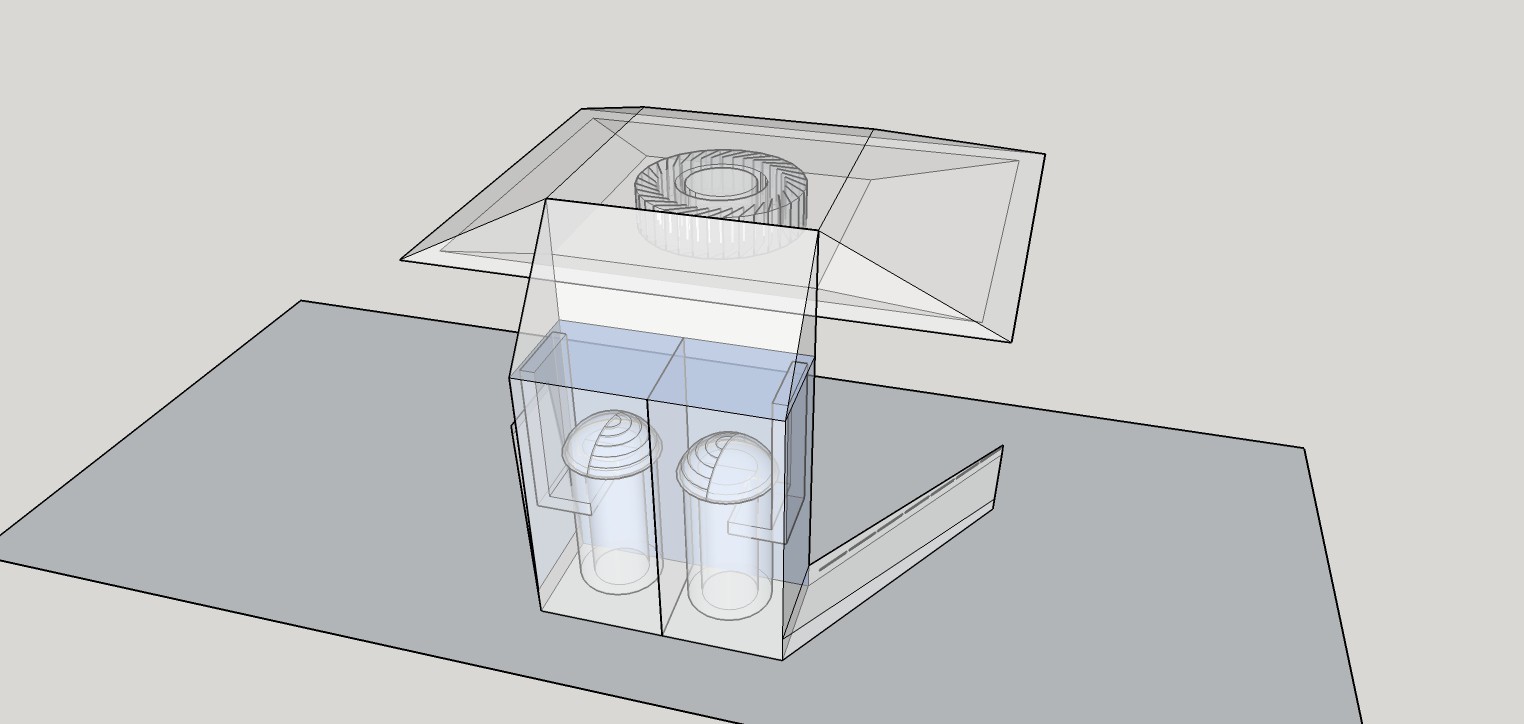
09/21/2015 at 06:25 • 0 commentsHere is what a consumer product implementation may look like. With the help of my wife, a sketchup model was produced of a counter top version of a wet scrubber recirculating hood. The rectangular hood would contain a centrifugal blower. The two stage electrified wet scrubber would exist in the central pillar, the cleaned air would exit at slits in the feet, directing air back into the hood to create an air blade "wall". This type of product form factor would be fitting for the kitchen and the laboratory.
-
HackadayPrize Semifinals Video Submission
09/20/2015 at 10:40 • 0 comments -
Redesigning and Rebuilding
09/20/2015 at 09:19 • 0 commentsI hit a few road blocks. I don't know how to measure performance below a 1um accuracy and I don't know how to ionize the incoming air without generating harmful Ozone. Walking around my living room with my hands in the air, my wife came to the rescue with a single sentance.
"Why not use water to ionize the air?" she said.
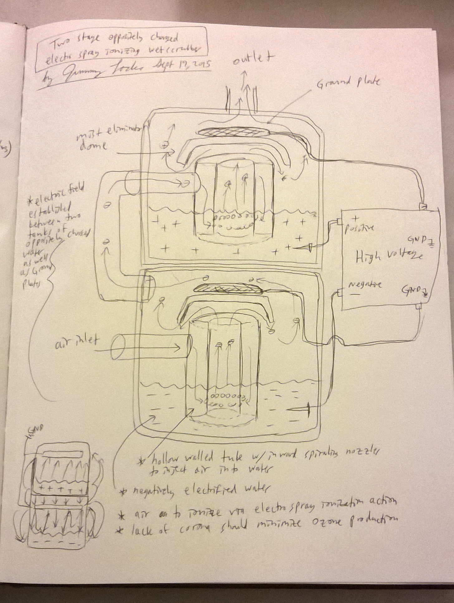
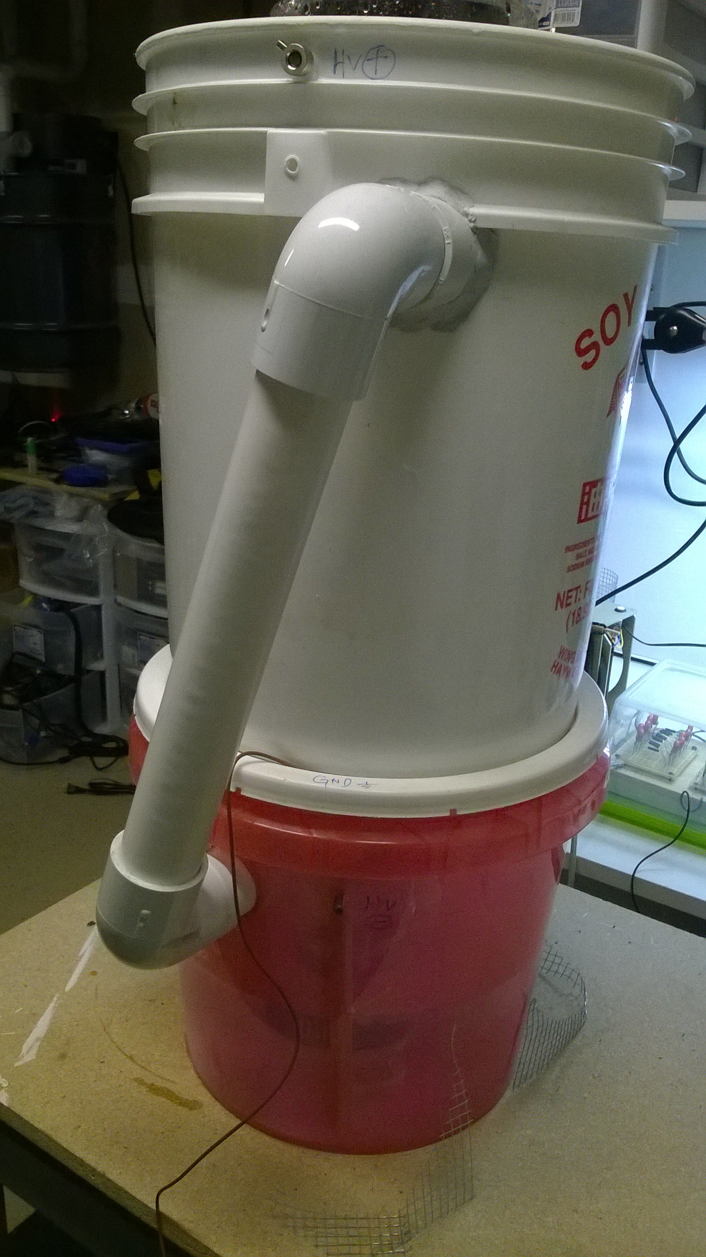
GENIUS! This led me to my current design. A two stage electrospray ionizing wet scrubber. Although I rebuilt the wet scrubber into a smaller form factor, I now had two wet scrubbers. I would use the first wet scrubber's liquid to charged the particulate laden air that passes through it; the particulates would be charged in a pseudo electrospray fashion. Then I would pipe the charged particulates into the second wet scrubber that is charged to an opposite polarity. Using water to ionize air would solve the Ozone problem as there would be no corona produced from the water spray. It was worth a shot! My original goal of making the whole unit smaller would have to wait, now this thing would become even more beastly! Muhahahahahahaha!
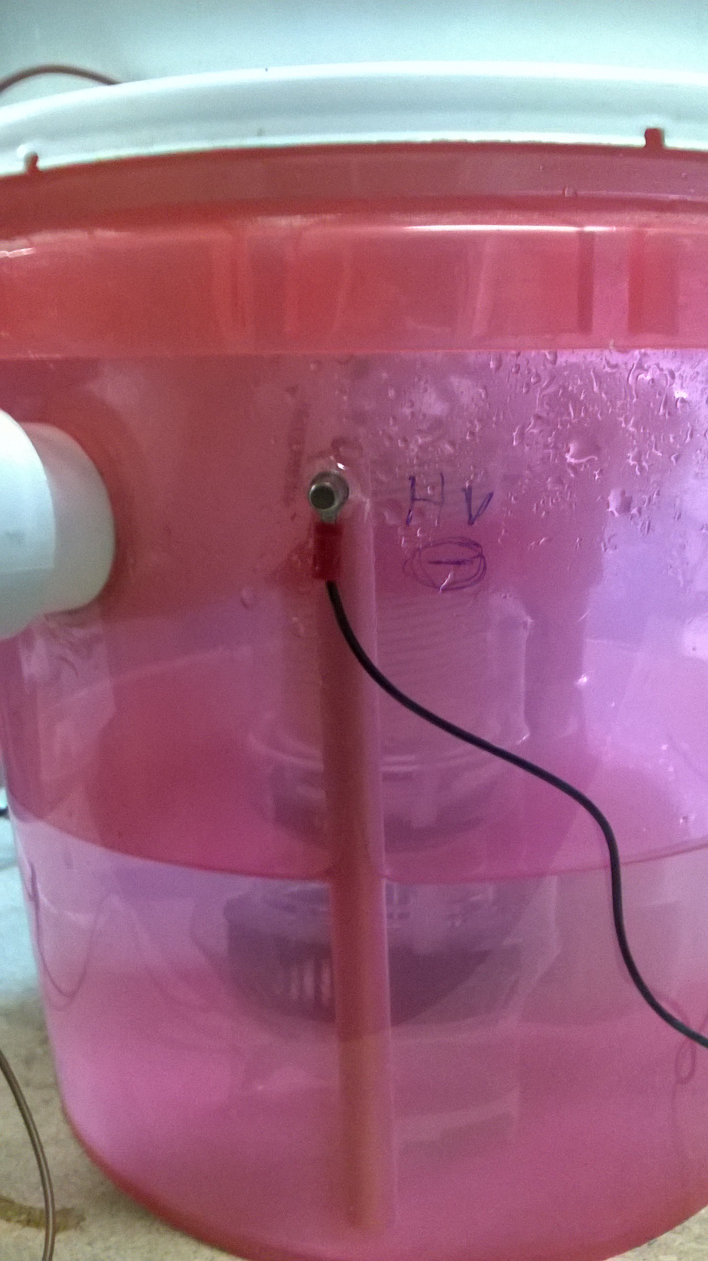
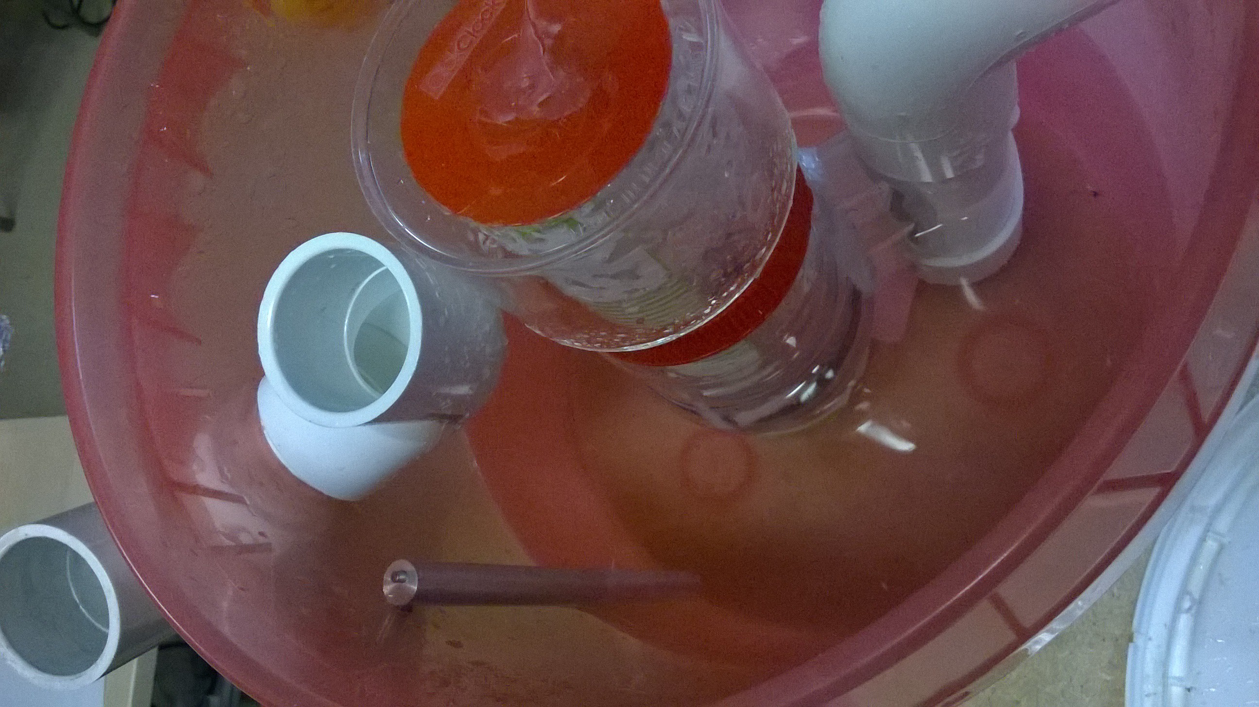
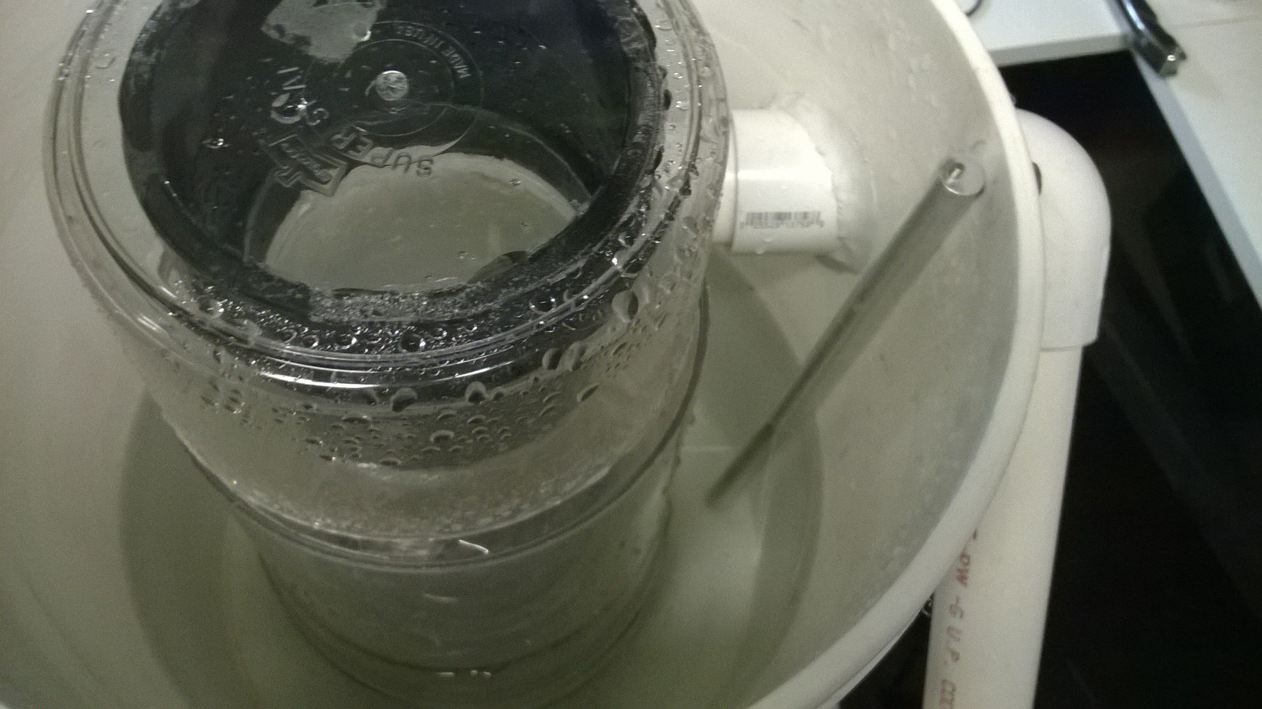
I added an aluminum rod to the inside of the smaller wet scrubber acting as a charging pole for the scrubbing liquid.

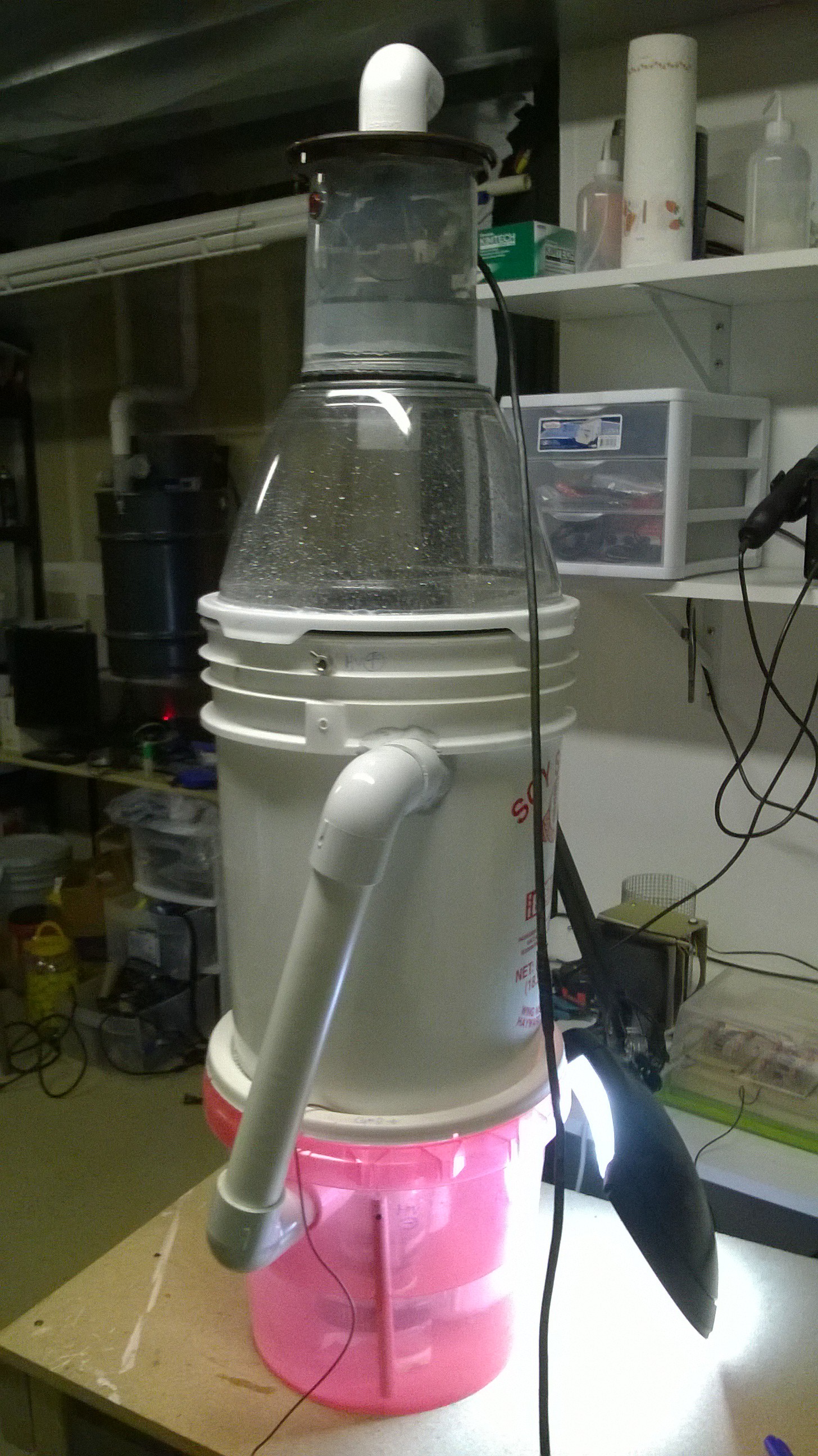
Next I simply stacked the second wet scrubber (the original prototype) on top of the smaller version and piped the output of the bottom scrubber into the inlet of the top scrubber.
The top scrubber also has the same rod on the inside to charge its scrubbing liquid to the opposite polarity of that of the scrubber below it.
I attached the clear domed lid, the vacuum motor, and the high voltage circuit.
Both wet scrubbers were filled with salt water and had opposite high voltage applied to them. Here is a video of a quick test run.
Household Electrically Enhanced Wet Scrubber
A household air purification unit for kitchens, labs, & smokers used to scrub fine particulates and VOC's out of the air.
