-
Ping... Ping... Ultrasonic Sensors
10/04/2015 at 14:43 • 0 commentsActually an ultrasonic sensor goes click.. click... Anyway let's start. The lidar was mounted at a height of approximately 71 cm from the ground. That would mean that any obstacles short than that, and there are plenty of those, will not be detected by the lidar. This would make collision avoidance difficult to say the least.
So what we planned was to have an array of inexpensive distance sensor, we chose ultrasonic sensors, to be mount close to the ground of collision avoidance. Infrared range finders also foot the bill if it was'nt for the fact that they don't work very well outdoor conditions or area fill with infrared light.
We chose the most inexpensive ultrasonic sensor we can find the Devantech SRF02:
![]()
It has a working range of about 15 cm to 300 cm making it suitable for our purpose. The working minimum distance is due to the fact that there is only one transducer which both generates the pulse and receives it. After sending a pulse, the transducer needs a certain amount of time to 'ring down'. This ring down time corresponds to a minimum working distance. If you really want to get a smaller minimum working distance from these sensors, you would need to use one to send the pulse and another to receiver it. Ultrasonic sensors with two transducers do not suffer from this issue.
The SRF02 can output distance in cm, in, and microseconds (used with speed of sound to calculate distance) over serial or I2C. It runs on a 5V supply. For our purpose, we would be using I2C communication as it allows up to 16 sensors to be chained together.
For controlling the sensor we used an Arduino Leonardo. No special reason for this choice other than it has a dedicated SDA and SCL pin. Ideally there should be a pull up of the two lines to 5 V using a 10 k resistor. However using the wire Arduino library should enable the internal pull up resistor.
The first order of business was to give each sensor an unique address. A caveat here is that the SRF02 uses a 8 bit addressing while the Arduino I2C uses 7 bit addressing. The way to convert from 8 bit to 7 bit addressing is to take the 7 highest bits of the 8 bit address.
When you power up the SRF02, it would flash its onboard led, a long pulse followed by a series of short pulses which indicate its address. For explanation of address changing, you can refer to http://www.robot-electronics.co.uk/htm/srf02techI2C.htm.
We have attached here the code for changing the address of the SRF02. As the credit shows, it was modified from codes written by Nicholas Zambetti and James Tichenor
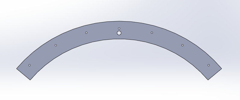
// I2C SRF02 Devantech Ultrasonic Ranger Finder
// by Nicholas Zambetti
// and James Tichenor
// Modified by Poh Hou Shun

// Address chnage of Devantech Ultrasonic Rangers SFR02

// Created 24 September 2015

// This example code is in the public domain.

#include

void setup() {

  Wire.begin();                // join i2c bus (address optional for master)
  changeAddress(0x71, 0xF6);   // change address, changeAddress(oldAddress(7 bits), newAddress (8 bits))
}

void loop() {}

// The following code changes the address of a Devantech Ultrasonic Range Finder (SRF02)
// usage: changeAddress(0x70, 0xE6);

void changeAddress(byte oldAddress, byte newAddress)
{

  Wire.beginTransmission(oldAddress);
  Wire.write(byte(0x00));
  Wire.write(byte(0xA0));
  Wire.endTransmission();

  Wire.beginTransmission(oldAddress);
  Wire.write(byte(0x00));
  Wire.write(byte(0xAA));
  Wire.endTransmission();

  Wire.beginTransmission(oldAddress);
  Wire.write(byte(0x00));
  Wire.write(byte(0xA5));
  Wire.endTransmission();

  Wire.beginTransmission(oldAddress);
  Wire.write(byte(0x00));
  Wire.write(newAddress);
  Wire.endTransmission();

}

/*

  Address 8 bit -> 7 bit map

  0xE0 -> 0x70
  0xE2 -> 0x71
  0xE4 -> 0x72
  0xE6 -> 0x73
  0xE8 -> 0x74
  0xEA -> 0x75
  0xEC -> 0x76
  0xEE -> 0x77
  0xF0 -> 0x78
  0xF2 -> 0x79
  0xF4 -> 0x7A
  0xF6 -> 0x7B
  0xF8 -> 0x7C
  0xFA -> 0x7D
  0xFC -> 0x7E
  0xFE -> 0x7F

 */
The next step was simply to write a code that request a measurement from a number of sensors. For our case, we chose to implement 12 sensors in a ring configuration. The code for driving a number of sensors is:/* * * rosserial srf02 Ultrasonic Ranger Example * * This example is calibrated for the srf02 Ultrasonic Ranger. * * By Poh Hou Shun 24 September 2015 */ //#include <Sonar_srf02.h> //srf02 specific library #include <Wire.h> //#include <ros.h> //#include <std_msgs/Float32.h> //Set up the ros node and publisher //std_msgs::Float32 sonar_msg; //ros::Publisher pub_sonar("sonar", &sonar_msg); //ros::NodeHandle nh; //Sonar_srf02 MySonar; //create MySonar object #define COMMANDREGISTER 0x00 #define RESULTREGISTER 0x02 #define CENTIMETERS 0x51 // use 0x50 for inches // use 0x51 for centimeters // use 0x52 for ping microseconds #define NO_OF_SENSORS 12 int SEQUENCE[] = {112, 113, 114, 115, 116, 117, 118, 119, 120, 121, 122, 123}; int reading = 0; String stringData; void setup() { Wire.begin(); // join i2c bus (address optional for master) Serial.begin(9600); // start serial communication at 9600bps //nh.initNode(); //nh.advertise(pub_sonar); } long publisher_timer; void loop() { if (millis() > publisher_timer || 1) { for (int i = 0; i < NO_OF_SENSORS; i++) { takeData(SEQUENCE[i]); } // step 2: wait for readings to happen delay(70); // datasheet suggests at least 65 milliseconds readData(SEQUENCE[0]); stringData = String(reading); Serial.print(reading); for (int i = 1; i < NO_OF_SENSORS; i++) { readData(SEQUENCE[i]); stringData = ' ' + String(reading); Serial.print(' '); Serial.print(reading); } //stringData = stringData + '\0'; //sonar_msg.data = stringData; //pub_sonar.publish(&sonar_msg); publisher_timer = millis() + 4000; //publish once a second //Serial.println(sensorReading); Serial.println('\0'); } //Serial.println(stringData); // print the reading //nh.spinOnce(); } void takeData(int address) { // step 1: instruct sensor to read echoes Wire.beginTransmission(address); // transmit to device #112 (0x70) // the address specified in the datasheet is 224 (0xE0) // but i2c adressing uses the high 7 bits so it's 112 Wire.write(byte(COMMANDREGISTER)); // sets register pointer to the command register (0x00) Wire.write(byte(CENTIMETERS)); // command sensor to measure in "centimeters" (0x51) Wire.endTransmission(); // stop transmitting } void readData(int address) { // step 3: instruct sensor to return a particular echo reading Wire.beginTransmission(address); // transmit to device #112 Wire.write(byte(RESULTREGISTER)); // sets register pointer to echo #1 register (0x02) Wire.endTransmission(); // stop transmitting // step 4: request reading from sensor Wire.requestFrom(address, 2); // request 2 bytes from slave device #112 // step 5: receive reading from sensor if (2 <= Wire.available()) { // if two bytes were received reading = Wire.read(); // receive high byte (overwrites previous reading) reading = reading << 8; // shift high byte to be high 8 bits reading |= Wire.read(); // receive low byte as lower 8 bits } //Serial.println(reading); }The code triggers each sensor in turn before querying them. This was done to save on waiting time due to the ring down. This code was supposed to trigger each ultrasonic sensor for a measurement and return it as a ROS topic. It is not implemented yet as the exact format of the topic was still not finalized.To hold the 12 ultrasonic sensors we need to fabricate a ring-shaped circuit board. We decided to go with three circuit boards, each having a radius of curvature of about 145 cm so that they fit the circumference of the base plate of the platform. Each segment would hold 4 sensors. We drew the outline in Solidworks. The large hold was for mounting the circuit board. The smaller holes served as markers for position to place the sensors when laying out the board. The plane view was then exported as a .dxf file.
![]()
We used the Eagle PCB design to draw the circuit schematics. For the board layout we used the file import-dxf-1_6.ulp from https://github.com/erikwilson/import-dxf to import .dxf file from earlier on which determines the shape of the circuit board. ULP refers to user language programming. It is like a script which is executed by Eagle. To run the file simply in board editor select File-> Run ULP. For this particular .ulp we found that the import only works with a metric setting. After that was done we continue with routing the board.
![]()
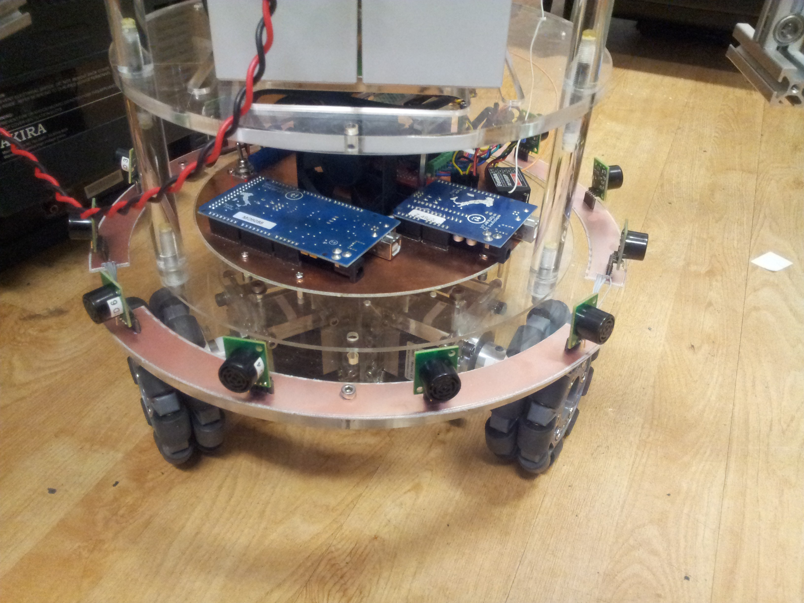
The final board design was then routed out. After populating with a number of headers and loads of botching to connect the ground planes. Finally the boards were connected together and installed.
![]()
Now we are in the process of testing the sensor array. First indication was that by taking measurement consecutively, there was some amount of crosstalk between the senors, i.e. pulse from one sensor is received by another. We would need to change the measurement sequence and massage the output so that it is compatible with a certain type of ROS sensor topic.
-
First Foray into ROS
10/04/2015 at 10:19 • 10 commentsNow it was time to tackle some of the software (talking about codes running on the computer not the firmware) side of things. The very first thing we did was to load our under-powered PC (it is a 32 bit system by the way) with the latest version of Ubuntu (14.04.3 LTS).
With it 'sudo apt-get updated, upgraded, and then dist-upgraded'. We are finally ready to install the 'Robot Operating System (ROS)'. For those who are not familiar with ROS, wikipedia calls it:
"Robot Operating System (ROS) is a collection of software frameworks for robot software development, (see also Robotics middleware) providing operating system-like functionality on a heterogeneous computer cluster. ".
Meanwhile we call it a kick ass software that ties the various components of a robot together. It has a large open-source community supported library to boot. Anyone who is really serious about robotics should take a look at it. This is also the first time getting our feet wet in the 'ROS lake'.
For our system we installed the most current version 'ROS Jade Turtle' (detailed instruction here) IN FULL (don't to leave out any important packages). The ROS website provides a series of excellent tutorials that really helped us... in the beginning (more on this later). In a nutshell, what we want to in ROS is to implement something called Hector SLAM (no it is not a WWE thing). Firstly SLAM is a abbreviation of Simultaneous Localization and Mapping. It refers to the process in which a robot (it can be any number of similar things) can in parallel map out an unknown area and at the same time determine its location in the map. This is helpful in getting a robot autonomously from point A to B.
Now Hector SLAM is something more advanced. It can build up a map without need for odometry. Let us explain: Imagine the lidar sensor we featured earlier. It outputs a distance versus polar angle kind of reading. When the sensor moves, the readings change, kind of like a scene A to B. Now the Hector SLAM algorithm is able to the components of A in B. Thus it does'nt require odometry input as a reference., although it can be augmented by it.
Now ROS rears its baffling head. It is well known to have a steep learning curve (maybe that is only for us). While there are a multitude of examples of sucessful implementation of RPLIDAR with Hector SLAM, there is not step by step instruction how to do it. After much toil we got it to work and we will document the steps here. Hope it is helpful:
First, one needs to get RPLIDAR to talk to ROS (we are making a major assumption that you are using Ubuntu), the steps for this procedure are:
1. Go to https://github.com/robopeak/rplidar_ros
2. Clone the folder listed on the site into your catkin's workspace src folder (assuming you are using Jade Turtle here)
3. Go the catkin directory: cd catkin
4. Source the setup.bash file (we found that we need to do this for every command prompt that we open to run ROS stuff): source /opt/ros/jade/setup.bash
5. Compile: catkin_make
6. After that is done connect the RPLIDAR and run your new spanning rplidar ros node (that is what it is called): roslaunch rplidar_ros view_rplidar.launch
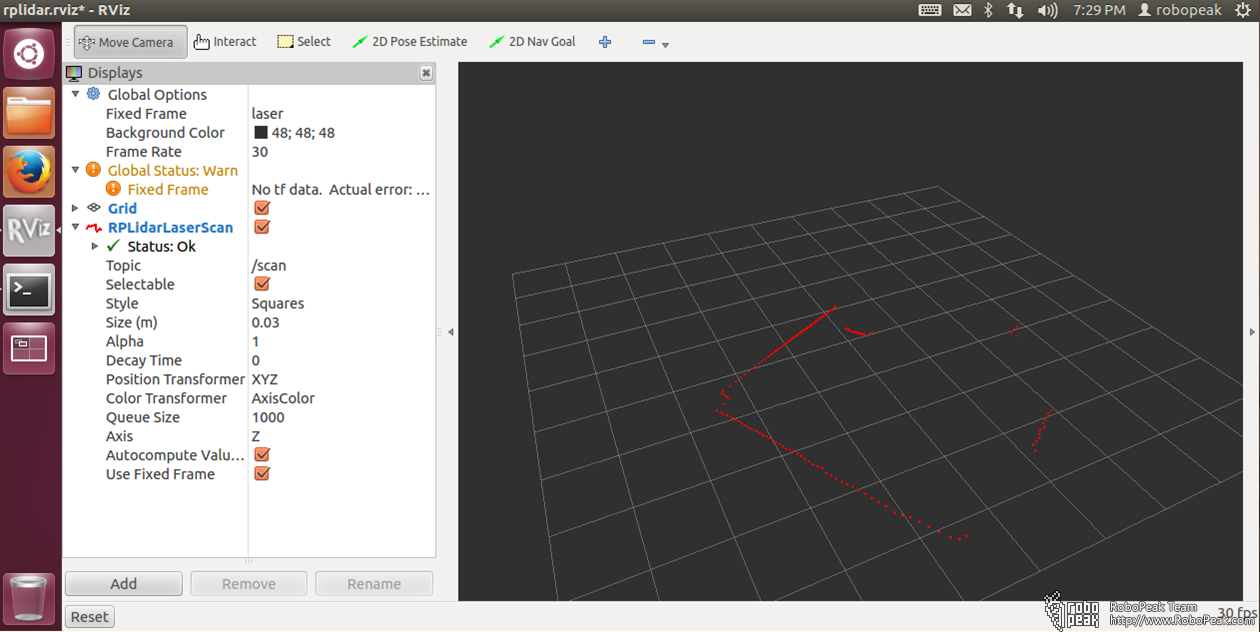
The last step open up what is call RVIZ which a ROS visualization program. What you should see is something like this:
![]() Now what you would immediately notice on the left is a warning about 'No tf data'. To put it simply it is trying to say that it is lacking in some defined reference frame. This will be a problem later on when trying to run Hector ROS.
Now what you would immediately notice on the left is a warning about 'No tf data'. To put it simply it is trying to say that it is lacking in some defined reference frame. This will be a problem later on when trying to run Hector ROS.Alternatively you can quit RVIZ and run the following two commands in separate command prompt (remember to source your setup.bash in both command prompt):
roslaunch rplidar_ros rplidar.launch
rosrun rplidar_ros rplidarNodeClient
to see the data stream.
Now the next step is to implement the Hector SLAM node itself. Here are the step:
1. Now clone the Hector SLAM package (https://github.com/tu-darmstadt-ros-pkg/hector_slam) into the src directiory.
2. Now from the catkin directory, source the setup.bash then run catkin_make hector_slam
3. Make the following modification to file ~/catkin_ws/src/hector_slam-catkin/hector_mapping/launch/mapping_default.launch
Change last second line:
<!--<node pkg="tf" type="static_transform_publisher" name="map_nav_broadcaster" args="0 0 0 0 0 0 map nav 100"/>-->
to:
<node pkg="tf" type="static_transform_publisher" name="base_to_laser_broadcaster" args="0 0 0 0 0 0 base_link laser 100" />
and save.
4. To start mapping do the following:
1. Start a command prompt and issue following commands
source devel/setup.bash
roslaunch rplidar_ros rplidar.launch2. Start another command prompt and issue following commands
source devel/setup.bash
roslaunch hector_slam_launch tutorial.launch
5. Now just move the lidar around... slowly... it should build up a map of the surrounding.
If you were to start the mapping without making the modification in step 3, no map would be generated.
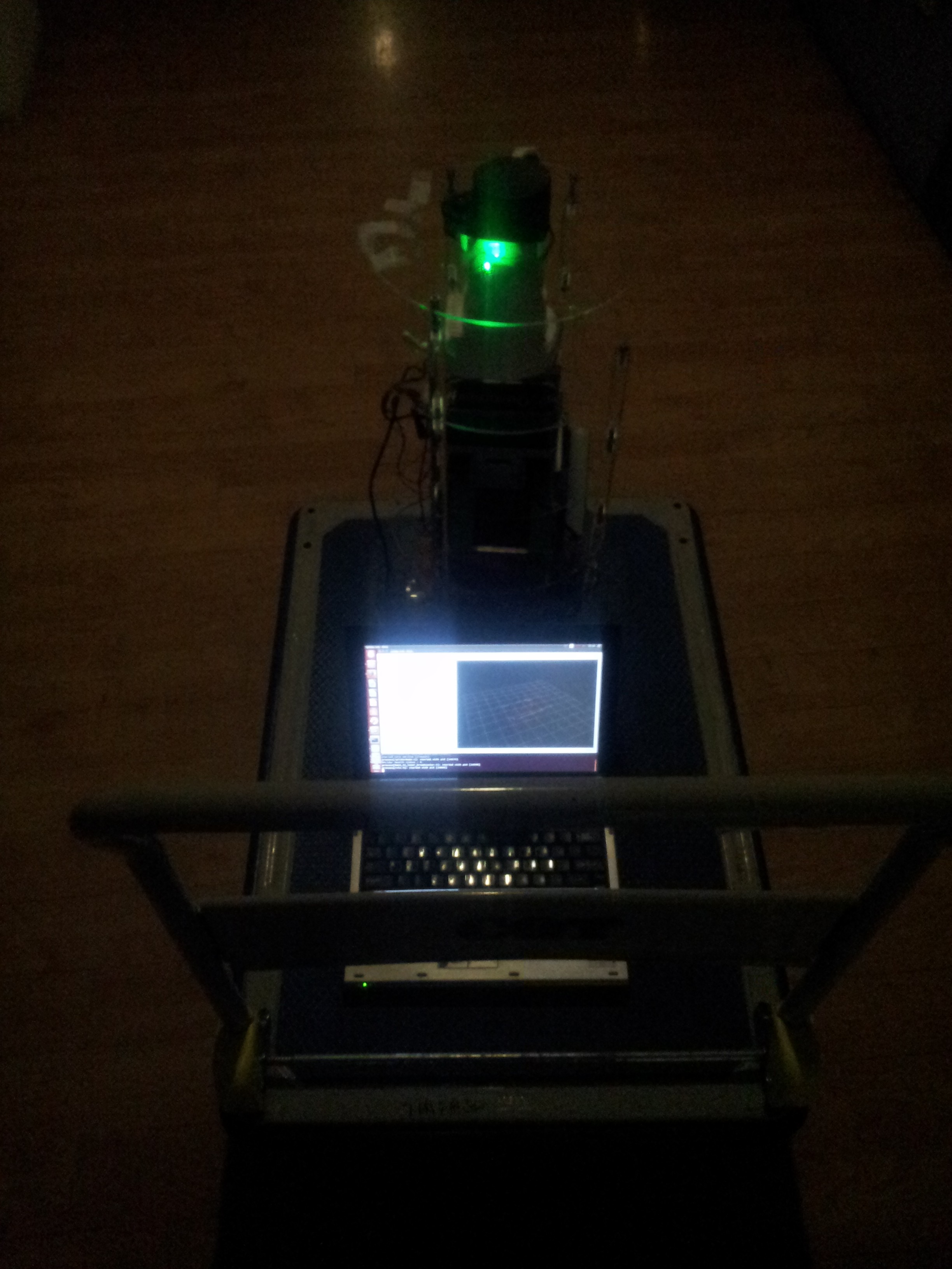
Here was our test set-up for the first mapping, the lidar was connected to a laptop and the platform moved around on a trolley. The problem here is that the lidar is picking up the trolley push bar. Since that is fixed structure as the platform was moved around, the algorithm got confused and did not manage to build up a map. Maybe there is a way of excluding certain data points from the mapping.
![]()
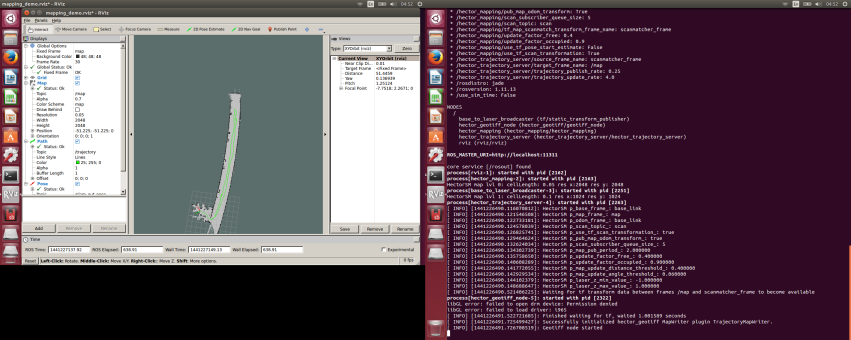
We then connected the lidar directly to the platform onboard pc and started the mapping via ssh over wifi. This ensure no part of the lidar was blocked. We drove the platform slowly up and down the corridor outside of our office and obtain this:
![]() The corridor was in fact straight. The fact that it appears curved here was possibly due to the fact that the wall on that side was exceptionally featureless. So the Hector SLAM algorithm may not be matching up the features accurately. Maybe implementation of the odometry input would help in this case.
The corridor was in fact straight. The fact that it appears curved here was possibly due to the fact that the wall on that side was exceptionally featureless. So the Hector SLAM algorithm may not be matching up the features accurately. Maybe implementation of the odometry input would help in this case. -
Modification to a Holomonic Base
10/04/2015 at 10:00 • 0 commentsAfter weeks of trying, we still did'nt manage to balance the test base on the ball. The torque from the steppers are simply too little to drive the base reliably. To add salt to injury, because the omni wheels are mounted at an angle, driving the base without the ball while possible, introduces loads of vibration due to the spacing between the roller. This rendered us unable to test any of the navigation sensors.
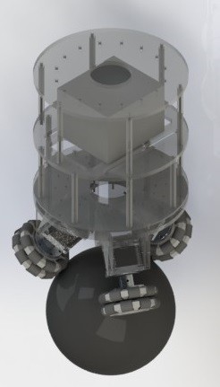
With the deadline for the our Tech Factor challenge looming, something mus be done. So as a compromise, we decided to redesign the base such that wheels are not mounted at an angled. For this configuration the base needs to be enlarged and the stepper mounts redesigned. Here is our design:
![]()
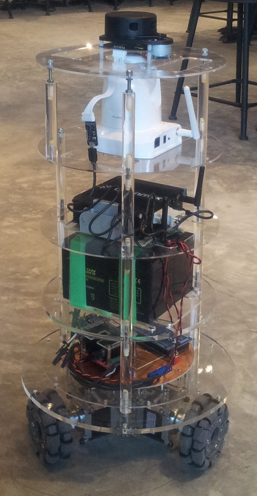
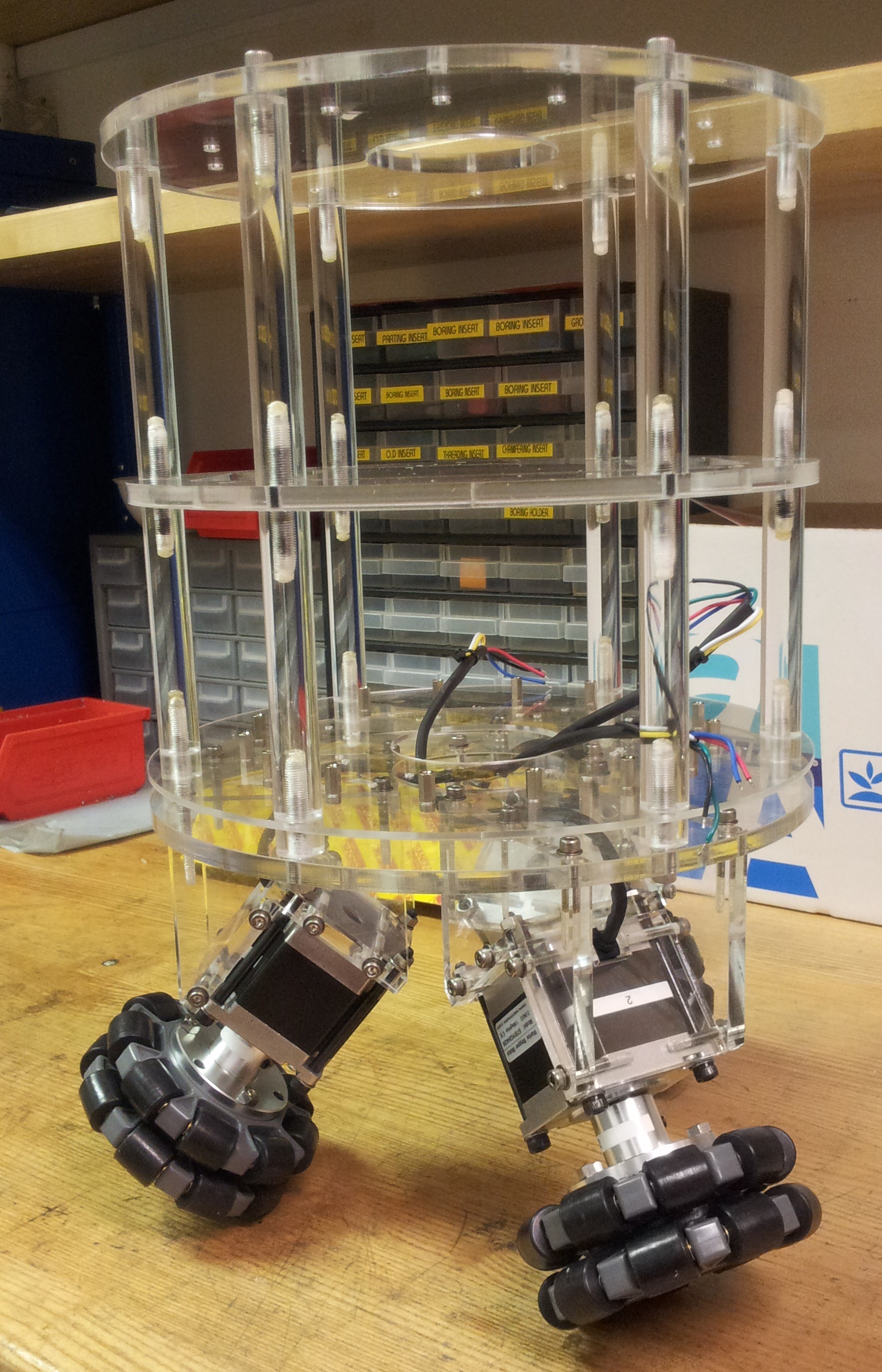
After extensive modification and upgrading, it looked like this:
![]()
After words about the upgrade. We have fitted two 12 V, 7 Ah sealed lead acid batteries. They are connected in parallel and power distributed by the driver interface board that we fabricated earlier. For the brain, we fitted a grossly under-powered QBOX-1000, a fan-less Box PC (the black box with two antennae sticking out) running Intel Atom Processor N270 with 2 Gb ram and a 64 Gb SSD (I believed). Above the brain we have mounted a Trendnet TV-IP651WI IP camera. This allows us to remotely drive the platform around and not 'kill' anyone. Lastly mounted above that is the RPLIDAR. The RPLIDAR came with a M2.5 threaded nylon spacers. For future compatibility to standard spacers, we re-tapped them to M3.
-
Seeing the Light with RPLIDAR
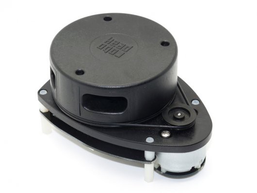
10/04/2015 at 09:35 • 0 commentsGood news everyone (in Professor Farnsworth's voice)! The first of our navigation sensor the RPLIDAR has arrived. We gotten ours from Seeedstudio for a little under 400 bucks. For those who are not familiar with the RPLIDAR, it is probably one of the cheapest lidar one can get on the market, without getting into "Poor Man's Lidar (PML)" . It has a range of about 6 m with a refresh range of 5.5 Hz and 2000 samples/s at 1 degree resolution. It works by sending out a modulated (intensity I supposed) laser beam which gets reflected from an obstacle. The return signal is then detected by an onboard camera and decoded (probably some timing measurement goodness here) for the distance measurement.
![]()
Included in the box is the RPLIDAR itself (fortunately), a 7-way ribbon cable, and some kind of serial to USB adapter with builtin power suppy for the lidar and its motor. For testing, using the adapter is probably the best beg as it just streams the measurement through USB. However with the adapter one cannot selectively control the power to the motor. Using the demo program we easily verified that the lidar was working.
An issue that we faced with our RPLIDAR was that the spinning head does not seem to be balanced. As it spins it was introducing a fair bit of vibration, but not enough to be a showstopper. Maybe in the future we will try to balance out the head.
-
Some Inital Balancing Tests
10/04/2015 at 04:22 • 0 commentsIt has been about 2 months since I have last updated the build logs, there have been lots of development since then. Now I shall attempt to document them in the next few logs.
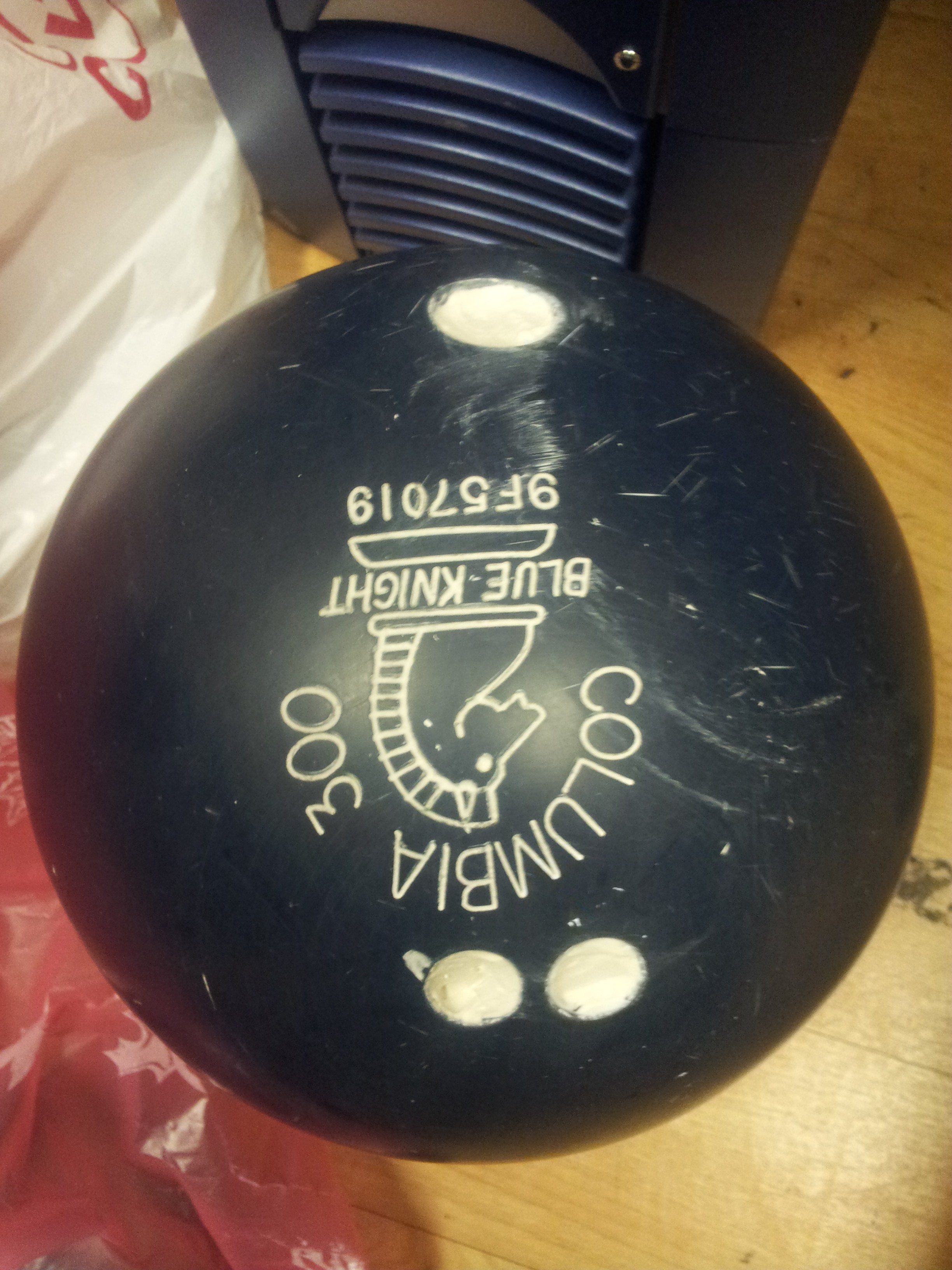
In the previous log, we documented that we have fabricated the test base together with a rudimentary drive electronics. Next, we tackled the task of getting the bowling ball for the test base. We gotten one from a thrift stall for a few bucks (not sure about the specifics of it except that it is approximately 20 cm in diameter. Sorry to all the bowling fans). We attempted to smooth out the finger holes and the debossed letterings with some plaster (we gathered there are fillers for this exact purpose, but unfortunately we cannot find any of them).
![]()
There was no other ways to describe the result except that it was BAD. It was very difficult to get a complete fill of the finger holes. Even when it was supposedly completely filled up, when it dries, the plaster would shrink. Anyway we were determined not to be stopped by a few finger holes, let us continue.
![]()
With the platform inverted we placed the bowling ball on the fabricated base under the tune of the theme of '2001: A Space Odyssey'... seriously. The omni wheels engages the bowling ball perfectly.
![]()
After changing some signs in the firmware, we managed to move the bowling ball in the intended direction. Although we still have not sorted out the part of moving in a straight line while rotating about its axis. A few issues we observed are: 1. Due to the size of the rollers on the omni wheels, there were gaps in between the two layers of rollers. Since the bowling ball engages the wheels in some weird way, there was significant vibration when we move the ball. 2. Two related issues. The steppers were rated at 2 A per phase. When we tried to crank up the current on the quadstepper, the driver would go into this erratic behavior mode. It seems that the driver chip (A4988) is overheating and going into some sort of thermal shutdown. This was despite the installed heatsink. Cooling it down using an inverted can of compressed air eliminated this behavior, thus confirming out diagnosis. Unfortunately due to the layout of the quadstepper board, there was no quick fix for the overheating issue.
The only thing we can do for the moment was to reduce the current to about 0.5 A, a level where the overheating issue seems to disappear. With the reduced current there was reduced torque. As we move the bowling ball, sometimes one or more steppers would stall. Of course in retrospect, the more expensive and complicated DC geared motors are better suited for the purpose.
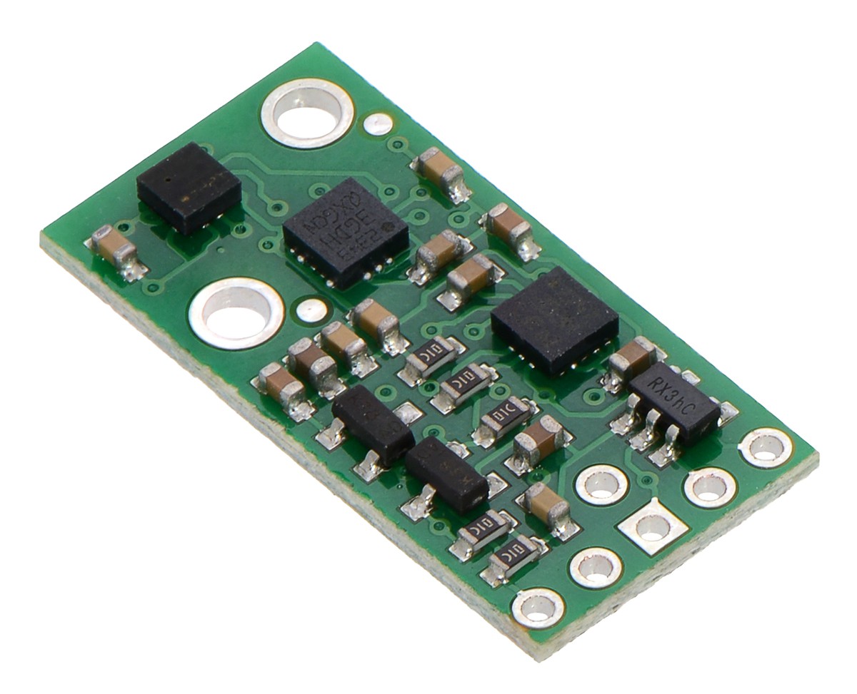
We popped in an AltIMU-10 IMU from Pololu and tried to balance the platform. the first thing we observed was a large latency, of about 1 sec, between tilting the platform and actuation that corrects for the tilt. With such large latency, no amount of playing around with the PID values would solve it. So back to the drawing board.
![]()
-
Firmware for the Stepper Controller
08/17/2015 at 18:00 • 0 commentsWe now begin coding the firmware for the stepper controller. Our conceptual leap was to realize that the code for driving the three stepper motors is the same as that driving a three holomonic robotic base. Basically the intended motion is resolved into three direction 120 degrees apart. The resolved motion is then translated into the motion of the three stepper motors. There are codes for handling mixing of linear and rotational motion. Lastly, there are some codes for implementing the balancing and head-locking, but these are commented out for initial tests.
//*************************************************************************************************************** /* Ballbot Firmware V1 Copyright (c) 2014 Space Trek Systems. http://www.spacetreksystems.com/ */ //*************************************************************************************************************** // header files #include "EasyTransferI2C.h" #include <PID_v1.h> //#include <TimerOne.h> #include <TimerThree.h> #include <TimerFour.h> #include <TimerFive.h> #include <Wire.h> //*************************************************************************************************************** //communication with reciever module //create object EasyTransferI2C ET; struct RECEIVE_DATA_STRUCTURE{ //put your variable definitions here for the data you want to send //THIS MUST BE EXACTLY THE SAME ON THE OTHER ARDUINO double Xspeedtrans; double Yspeedtrans; double Rotationtrans; }; //give a name to the group of data RECEIVE_DATA_STRUCTURE senddata; //define slave i2c address #define I2C_SLAVE_ADDRESS 9 //*************************************************************************************************************** //imu definition /* MinIMU-9-Arduino-AHRS Pololu MinIMU-9 + Arduino AHRS (Attitude and Heading Reference System) Copyright (c) 2011 Pololu Corporation. http://www.pololu.com/ MinIMU-9-Arduino-AHRS is based on sf9domahrs by Doug Weibel and Jose Julio: http://code.google.com/p/sf9domahrs/ sf9domahrs is based on ArduIMU v1.5 by Jordi Munoz and William Premerlani, Jose Julio and Doug Weibel: http://code.google.com/p/ardu-imu/ MinIMU-9-Arduino-AHRS is free software: you can redistribute it and/or modify it under the terms of the GNU Lesser General Public License as published by the Free Software Foundation, either version 3 of the License, or (at your option) any later version. MinIMU-9-Arduino-AHRS is distributed in the hope that it will be useful, but WITHOUT ANY WARRANTY; without even the implied warranty of MERCHANTABILITY or FITNESS FOR A PARTICULAR PURPOSE. See the GNU Lesser General Public License for more details. You should have received a copy of the GNU Lesser General Public License along with MinIMU-9-Arduino-AHRS. If not, see . */ // Uncomment the below line to use this axis definition: // X axis pointing forward // Y axis pointing to the right // and Z axis pointing down. // Positive pitch : nose up // Positive roll : right wing down // Positive yaw : clockwise int SENSOR_SIGN[9] = { 1,1,1,-1,-1,-1,1,1,1}; //Correct directions x,y,z - gyro, accelerometer, magnetometer // Uncomment the below line to use this axis definition: // X axis pointing forward // Y axis pointing to the left // and Z axis pointing up. // Positive pitch : nose down // Positive roll : right wing down // Positive yaw : counterclockwise //int SENSOR_SIGN[9] = {1,-1,-1,-1,1,1,1,-1,-1}; //Correct directions x,y,z - gyro, accelerometer, magnetometer // tested with Arduino Uno with ATmega328 and Arduino Duemilanove with ATMega168 // LSM303 accelerometer: 8 g sensitivity // 3.9 mg/digit; 1 g = 256 #define GRAVITY 256 //this equivalent to 1G in the raw data coming from the accelerometer #define ToRad(x) ((x)*0.01745329252) // *pi/180 #define ToDeg(x) ((x)*57.2957795131) // *180/pi // L3G4200D gyro: 2000 dps full scale // 70 mdps/digit; 1 dps = 0.07 #define Gyro_Gain_X 0.007 //X axis Gyro gain #define Gyro_Gain_Y 0.007 //Y axis Gyro gain #define Gyro_Gain_Z 0.007 //Z axis Gyro gain #define Gyro_Scaled_X(x) ((x)*ToRad(Gyro_Gain_X)) //Return the scaled ADC raw data of the gyro in radians for second #define Gyro_Scaled_Y(x) ((x)*ToRad(Gyro_Gain_Y)) //Return the scaled ADC raw data of the gyro in radians for second #define Gyro_Scaled_Z(x) ((x)*ToRad(Gyro_Gain_Z)) //Return the scaled ADC raw data of the gyro in radians for second // LSM303 magnetometer calibration constants; use the Calibrate example from // the Pololu LSM303 library to find the right values for your board #define M_X_MIN -421 #define M_Y_MIN -639 #define M_Z_MIN -238 #define M_X_MAX 424 #define M_Y_MAX 295 #define M_Z_MAX 472 #define Kp_ROLLPITCH 0.02 #define Ki_ROLLPITCH 0.00002 #define Kp_YAW 1.2 #define Ki_YAW 0.00002 /*For debugging purposes*/ //OUTPUTMODE=1 will print the corrected data, //OUTPUTMODE=0 will print uncorrected data of the gyros (with drift) #define OUTPUTMODE 1 //#define PRINT_DCM 0 //Will print the whole direction cosine matrix #define PRINT_ANALOGS 0 //Will print the analog raw data #define PRINT_EULER 1 //Will print the Euler angles Roll, Pitch and Yaw #define STATUS_LED 13 float G_Dt = 0.02; // Integration time (DCM algorithm) We will run the integration loop at 50Hz if possible long timer = 0; //general purpuse timer long timer_old; long timer24 = 0; //Second timer used to print values int AN[6]; //array that stores the gyro and accelerometer data int AN_OFFSET[6]={ 0,0,0,0,0,0}; //Array that stores the Offset of the sensors int gyro_x; int gyro_y; int gyro_z; int accel_x; int accel_y; int accel_z; int magnetom_x; int magnetom_y; int magnetom_z; float c_magnetom_x; float c_magnetom_y; float c_magnetom_z; float MAG_Heading; float Accel_Vector[3]= { 0,0,0}; //Store the acceleration in a vector float Gyro_Vector[3]= { 0,0,0};//Store the gyros turn rate in a vector float Omega_Vector[3]= { 0,0,0}; //Corrected Gyro_Vector data float Omega_P[3]= { 0,0,0};//Omega Proportional correction float Omega_I[3]= { 0,0,0};//Omega Integrator float Omega[3]= { 0,0,0}; // Euler angles float roll; float pitch; float yaw; float errorRollPitch[3]= { 0,0,0}; float errorYaw[3]= { 0,0,0}; unsigned int counter=0; byte gyro_sat=0; float DCM_Matrix[3][3]= { { 1,0,0 } ,{ 0,1,0 } ,{ 0,0,1 } }; float Update_Matrix[3][3]={ { 0,1,2 } ,{ 3,4,5 } ,{ 6,7,8 } }; //Gyros here float Temporary_Matrix[3][3]={ { 0,0,0 } ,{ 0,0,0 } ,{ 0,0,0 } }; //*************************************************************************************************************** // PID loop double Xspeed, Yspeed, Rotation; //double pitchSet, rollSet, yawSet; //double pitchAngle, rollAngle, yawAngle; //initialise PID loops //PID pitchPID(&pitchAngle, &Xspeed, &pitchSet, 700, 0, 0, DIRECT); //PID rollPID(&rollAngle, &Yspeed, &rollSet, 700, 0, 0, DIRECT); //PID yawPID(&yawAngle, &Rotation, &yawSet, 100, 0, 0, DIRECT); //*************************************************************************************************************** //stepper driver //defining const double STEP = 0.0982;//100*pi/200/16 (mm, for wheel) //const double STEP = 0.00014394;//(100*pi/2*108.55*pi)/200/16 (mm, for ball roller) //defining pins assignment (control pins for quadstepper) //channel mapping 1->X, 2->Y, and 3->Z const int XPUL = 11, XDIR = 36, XENABLE = A1; const int YPUL = 5, YDIR = 9, YENABLE = 10; const int ZPUL = 6, ZDIR = 23, ZENABLE= 22; //defining pins assignment (mircrostep selection for quadstepper) const int XMS1 = A8, XMS2 = A9, XMS3 = A10; const int YMS1 = 8, YMS2 = 7, YMS3 = 4; const int ZMS1 = 24, ZMS2 = 25, ZMS3 = 26; //static double mag, angle, rotation; //static double angle_ref = 0; //const double RADIUS = 83.154; //const double DEG2RAD = 1000/57296; double xspeed, yspeed, zspeed; long x_t, y_t, z_t; long prev_time = micros(); //const int NUMBER_OF_FIELDS = 3; // how many comma separated fields we expect //int fieldIndex = 0; // the current field being received //double values[NUMBER_OF_FIELDS]; // array holding values for all the fields //boolean negative = false; //*************************************************************************************************************** //reciever input //const int XRECPIN = 27, YRECPIN = 28, YAWRECPIN = 29; //const double MAXSPEED = 200, MINSPEED = -200; //(mms^-1) //const double MAXROTSPEED = 200, MINROTSPEED = -200; //(degs^-1) //const long DEADZONEUPPERLIMIT = 1520, DEADZONELOWERLIMIT = 1480; //const long TIMEOUT = 2500; //const int MAXVALUE = 2000, MINVALUE = 1000; //*************************************************************************************************************** // initialisation subroutines void init_stepper() { pinMode(XPUL,OUTPUT); pinMode(XDIR,OUTPUT); pinMode(XENABLE, OUTPUT); pinMode(XMS1, OUTPUT); pinMode(XMS2, OUTPUT); pinMode(XMS3, OUTPUT); pinMode(YPUL,OUTPUT); pinMode(YDIR,OUTPUT); pinMode(YENABLE, OUTPUT); pinMode(YMS1, OUTPUT); pinMode(YMS2, OUTPUT); pinMode(YMS3, OUTPUT); pinMode(ZPUL,OUTPUT); pinMode(ZDIR,OUTPUT); pinMode(ZENABLE, OUTPUT); pinMode(ZMS1, OUTPUT); pinMode(ZMS2, OUTPUT); pinMode(ZMS3, OUTPUT); digitalWrite(XMS1, HIGH); digitalWrite(XMS2, HIGH); digitalWrite(XMS3, HIGH); digitalWrite(YMS1, HIGH); digitalWrite(YMS2, HIGH); digitalWrite(YMS3, HIGH); digitalWrite(ZMS1, HIGH); digitalWrite(ZMS2, HIGH); digitalWrite(ZMS3, HIGH); digitalWrite(XENABLE, LOW); digitalWrite(YENABLE, LOW); digitalWrite(ZENABLE, LOW); //Timer1.initialize(1000000); Timer3.initialize(1000000); Timer4.initialize(1000000); Timer5.initialize(1000000); } /* void init_imu() { pinMode (STATUS_LED, OUTPUT); // Status LED I2C_Init(); digitalWrite(STATUS_LED,LOW); delay(1500); Accel_Init(); Compass_Init(); Gyro_Init(); delay(20); for(int i = 0; i < 32; i++) // We take some readings... { Read_Gyro(); Read_Accel(); for(int y=0; y<6; y++) // Cumulate values AN_OFFSET[y] += AN[y]; delay(20); } for(int y = 0; y < 6; y++) AN_OFFSET[y] = AN_OFFSET[y]/32; AN_OFFSET[5]-=GRAVITY*SENSOR_SIGN[5]; //Serial.println("Offset:"); for(int y = 0; y < 6; y++) Serial.println(AN_OFFSET[y]); delay(2000); digitalWrite(STATUS_LED,HIGH); timer=millis(); delay(20); counter=0; } void init_pid() { //intialising PID set values pitchSet = 0; rollSet = 0; yawSet = 0; Xspeed = 0; Yspeed = 0; Rotation = 0; //turn the PID on pitchPID.SetMode(AUTOMATIC); rollPID.SetMode(AUTOMATIC); yawPID.SetMode(MANUAL); pitchPID.SetOutputLimits(-100, 100); rollPID.SetOutputLimits(-100, 100); yawPID.SetOutputLimits(-180, 180); pitchPID.SetSampleTime(200); rollPID.SetSampleTime(200); yawPID.SetSampleTime(200); } void init_control() { pinMode(XRECPIN, INPUT); pinMode(YRECPIN, INPUT); pinMode(YAWRECPIN, INPUT); }*/ void init_control() { Wire.begin(I2C_SLAVE_ADDRESS); //start the library, pass in the data details and the name of the serial port. Can be Serial, Serial1, Serial2, etc. ET.begin(details(senddata), &Wire); //define handler function on receiving data Wire.onReceive(receive); } //*************************************************************************************************************** // actuation subroutines /* void imu_act() { if((millis() - timer)>=20) // Main loop runs at 50Hz { Serial.println("imu act"); counter++; timer_old = timer; timer = millis(); if (timer > timer_old) G_Dt = (timer-timer_old)/1000.0; // Real time of loop run. We use this on the DCM algorithm (gyro integration time) else G_Dt = 0; // *** DCM algorithm // Data adquisition Read_Gyro(); // This read gyro data Read_Accel(); // Read I2C accelerometer if (counter > 5) // Read compass data at 10Hz... (5 loop runs) { counter=0; Read_Compass(); // Read I2C magnetometer Compass_Heading(); // Calculate magnetic heading } // Calculations... Matrix_update(); Normalize(); Drift_correction(); Euler_angles(); //printdata(); } } void pid_act() { Serial.println("pid act"); pitchAngle = double(pitch); rollAngle = double(roll); yawAngle = double(yaw); pitchPID.Compute(); rollPID.Compute(); yawPID.Compute(); } */ /*void control() { unsigned long xrecpindur = pulseIn(XRECPIN, HIGH); //unsigned long yrecpindur = pulseIn(YRECPIN, HIGH); //unsigned long yawrecpindur = pulseIn(YAWRECPIN, HIGH); unsigned long yrecpindur = 1500; unsigned long yawrecpindur = 1500; if(xrecpindur != 0) { if(xrecpindur < DEADZONELOWERLIMIT || xrecpindur > DEADZONEUPPERLIMIT) { Xspeed = map(xrecpindur, MINVALUE, MAXVALUE, MINSPEED, MAXSPEED); } else { Xspeed = 0; } } if(yrecpindur != 0) { if(yrecpindur < DEADZONELOWERLIMIT || yrecpindur > DEADZONEUPPERLIMIT) { Yspeed = map(yrecpindur, MINVALUE, MAXVALUE, MINSPEED, MAXSPEED); } else { Yspeed = 0; } } if(yawrecpindur != 0) { if(yawrecpindur < DEADZONELOWERLIMIT || yawrecpindur > DEADZONEUPPERLIMIT) { Rotation = map(yawrecpindur, MINVALUE, MAXVALUE, MINROTSPEED, MAXROTSPEED); } else { Rotation = 0; } } }*/ void control() { if(ET.receiveData()) { //this is how you access the variables. [name of the group].[variable name] Xspeed = senddata.Xspeedtrans; Yspeed = senddata.Yspeedtrans; Rotation = senddata.Rotationtrans; } } //*************************************************************************************************************** // stepper driver subroutines void stepper_act() { //Serial.println("stepper act"); speed(Xspeed, Yspeed, Rotation); if(xspeed != 0) x_t = int(STEP/abs(xspeed)*1000000); //time (us) for 1 step at xspeed if(yspeed != 0) y_t = int(STEP/abs(yspeed)*1000000); //time (us) for 1 step at yspeed if(zspeed != 0) z_t = int(STEP/abs(zspeed)*1000000); //time (us) for 1 step at zspeed if(xspeed > 0) digitalWrite(XDIR, HIGH); else digitalWrite(XDIR, LOW); if(yspeed > 0) digitalWrite(YDIR, HIGH); else digitalWrite(YDIR, LOW); if(zspeed >0) digitalWrite(ZDIR, HIGH); else digitalWrite(ZDIR, LOW); xMove(xspeed); yMove(yspeed); zMove(zspeed); } void speed(double XSpeed, double YSpeed, double Rotation) { long time_step = micros() - prev_time; prev_time = micros(); xspeed = XSpeed + 83.154*ToRad(Rotation); yspeed = YSpeed*0.866 - XSpeed*0.5 + 83.154*ToRad(Rotation); zspeed = -YSpeed*0.866 - XSpeed*0.5 + 83.154*ToRad(Rotation); } void xMove(double xs) { if(xs != 0) { Timer5.setPeriod(x_t/2); Timer5.attachInterrupt(xPulse); } else { Timer5.detachInterrupt(); } } void yMove(double ys) { if(ys != 0) { Timer3.setPeriod(y_t/2); Timer3.attachInterrupt(yPulse); } else { Timer3.detachInterrupt(); } } void zMove(double zs) { if(zs != 0) { Timer4.setPeriod(z_t/2); Timer4.attachInterrupt(zPulse); } else { Timer4.detachInterrupt(); } } void xPulse() { digitalWrite(XPUL, digitalRead(XPUL) ^ 1); } void yPulse() { digitalWrite(YPUL, digitalRead(YPUL) ^ 1); } void zPulse() { digitalWrite(ZPUL, digitalRead(ZPUL) ^ 1); } //*************************************************************************************************************** //setup void setup() { Serial.begin(115200); //Serial1.begin(115200); Serial.println("ballbot firmware v1"); init_control(); Serial.println("control initialized."); //init_imu(); //Serial.println("imu initialized."); //init_pid(); //Serial.println("pid loops initialized."); init_stepper(); Serial.println("stepper driver initialized"); } //main Loop void loop() { control(); //imu_act(); //pid_act(); stepper_act(); /*Serial.print(pitch); Serial.print(","); Serial.print(roll); Serial.print(","); Serial.print(yaw); Serial.print(",");*/ Serial.print(Xspeed); Serial.print(","); Serial.print(Yspeed); Serial.print(","); Serial.print(Rotation); Serial.print(","); Serial.print(xspeed); Serial.print(","); Serial.print(yspeed); Serial.print(","); Serial.print(zspeed); Serial.println(";"); } void receive(int numBytes) {} //*************************************************************************************************************** -
Stepper Controller Electonics
08/17/2015 at 17:47 • 0 commentsThe controlling the stepper, we used the quadstepper board from Sparksfun. Heatsinks were placed on the controller chip to prevent overheating.
![]()
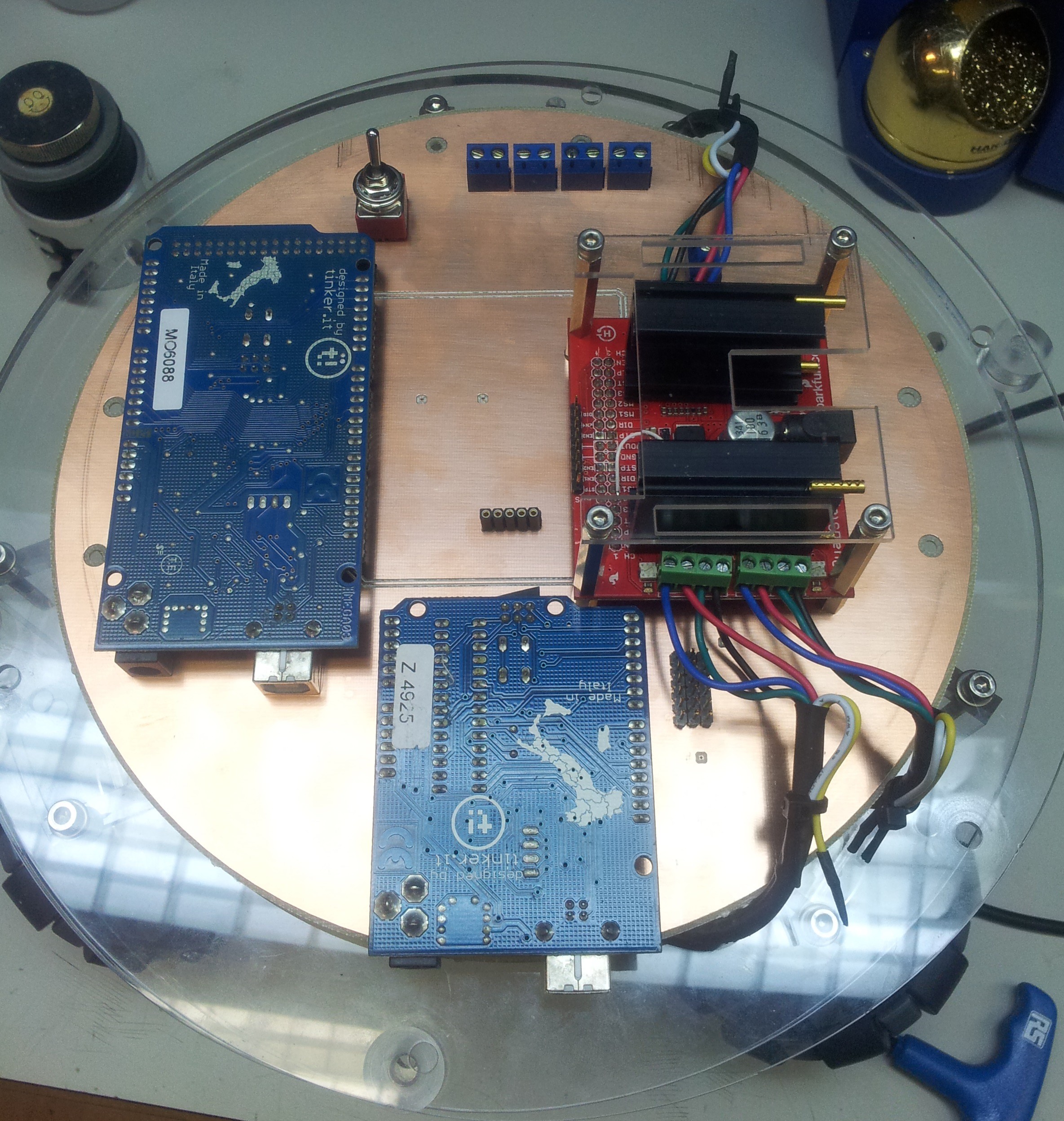
This is controlled solely by an Arduino Mega which generate the stepping pulses. An Arduino Mega was chosen because it has enough hardware timer for generating the stepping pulses. Another Arduino Uno serve to decode the PWM signal from an RC receiver. The decode signals are then sent to the Arduino Mega via I2C, so that the stepper motors can be remotely controller. An interface board is fabricated to tie all the components together. After alot of botching, the circuit finally works.
![]()
![]()
![]()
-
Ball Balancing Test Base Fabrication and Assembly
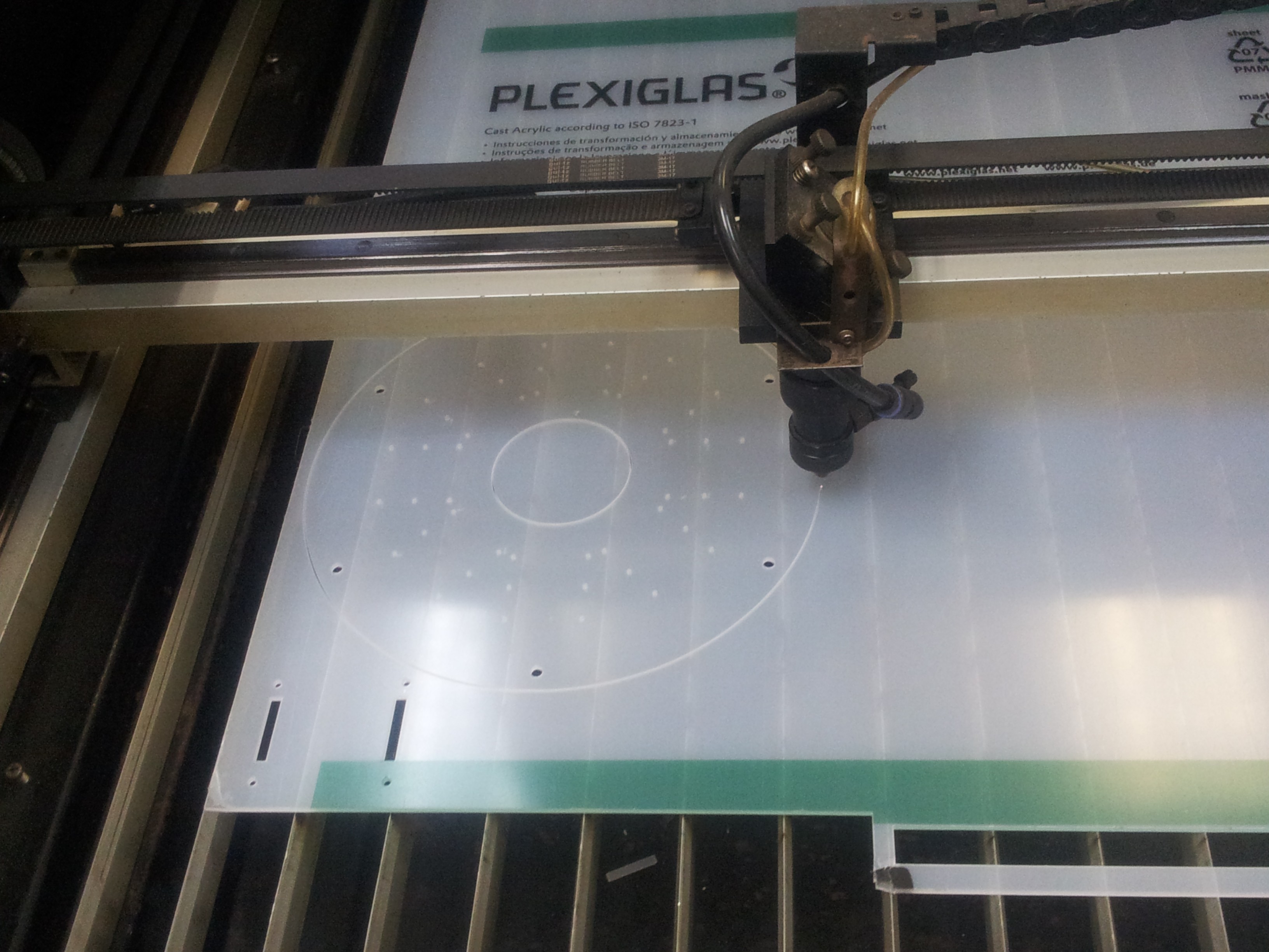
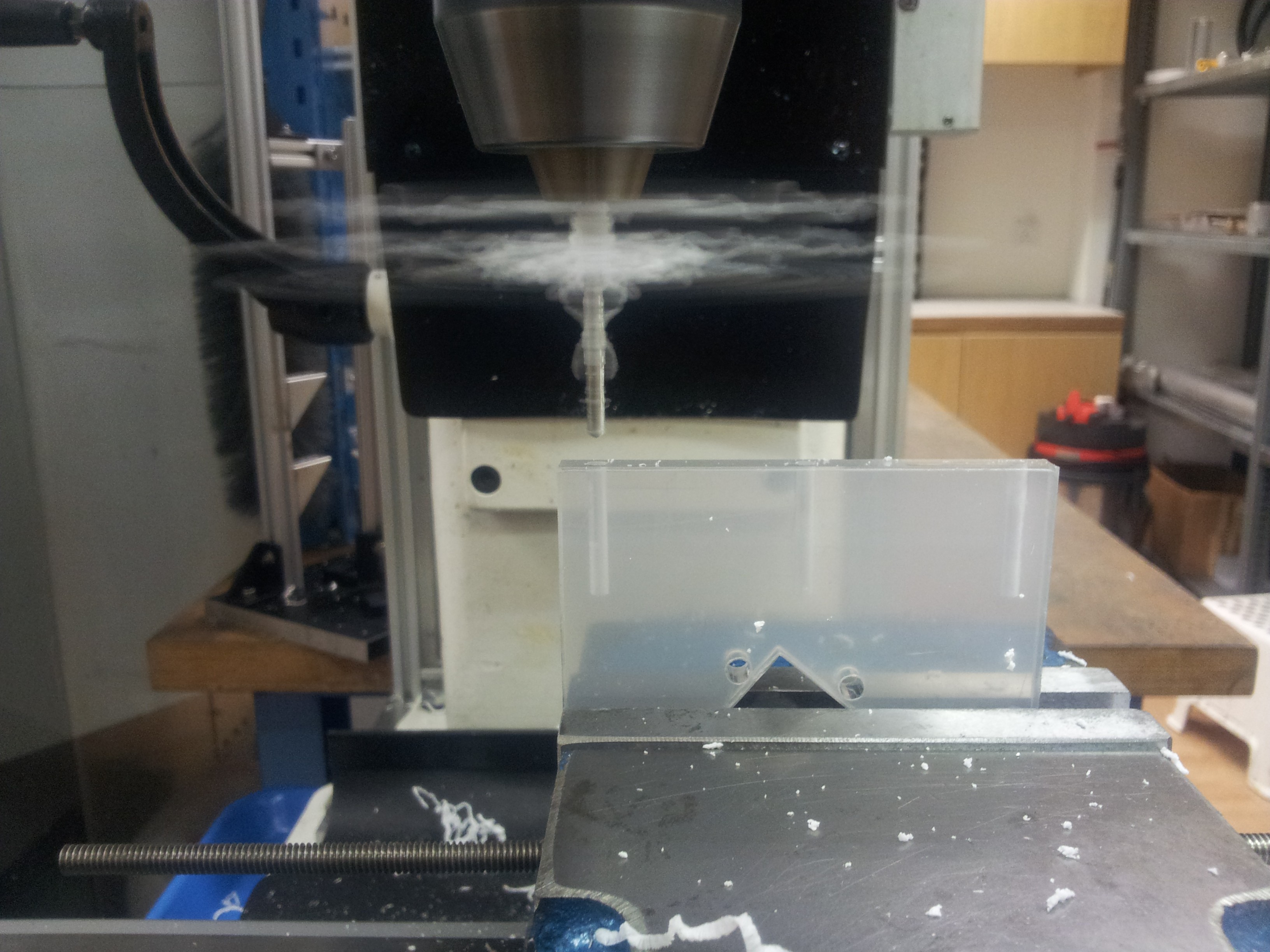
08/17/2015 at 16:24 • 0 commentsThe designs for the balancing test base were done in Solidworks and exported to .dxf files. These were then brought out for laser cutting. Instead of acrylic, plexiglas (also a type of acrylic) was used. We found that plexiglas is more flexible and stands up the rigor of drilling without cracking.
![]()
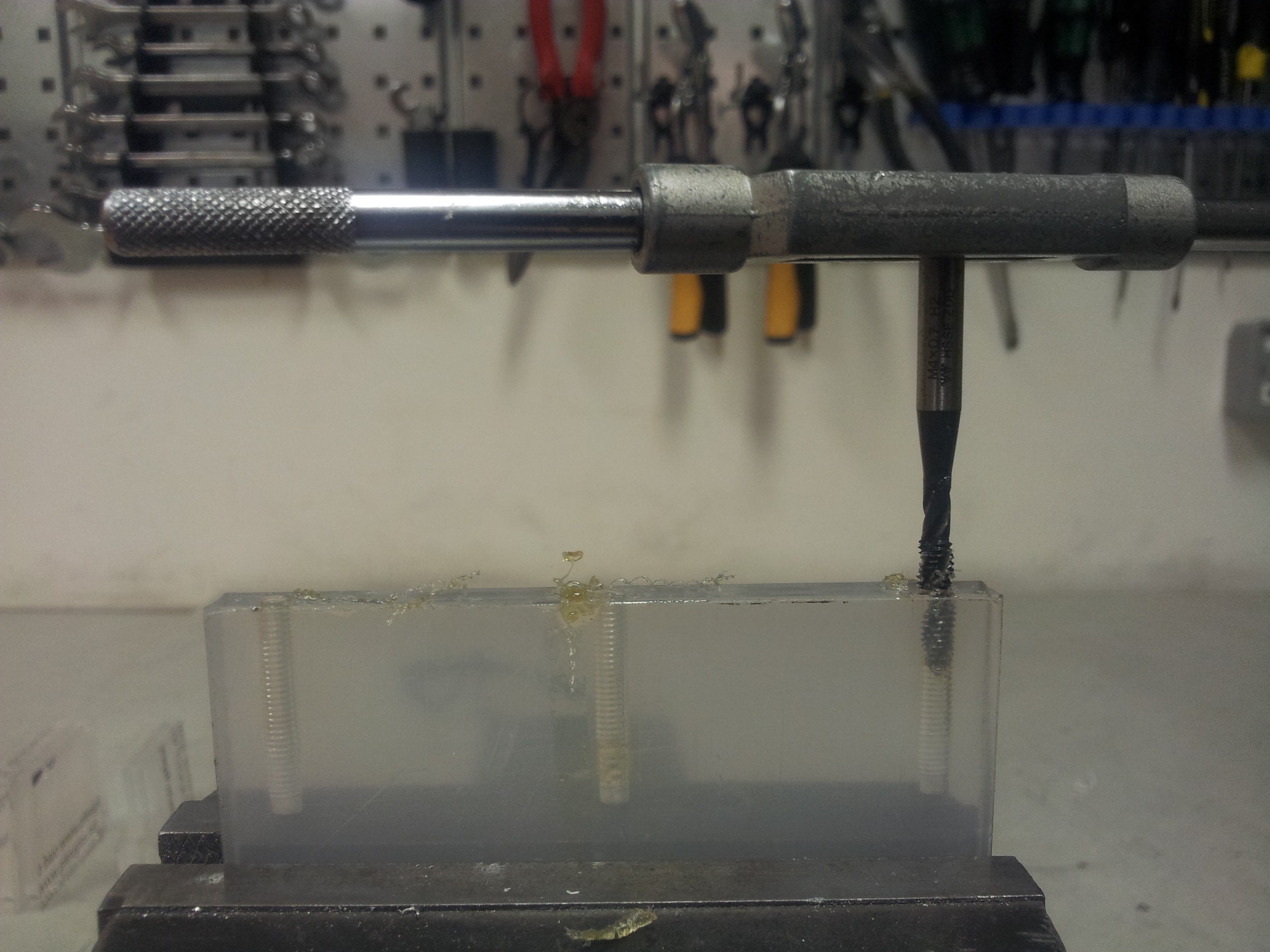
With all the pieces back from the laser cutter, we begin the ardous task of drilling all the holes for securing the mount for the stepper motor. Holes of 3.5mm diameter were drilled and tapped for M4 screws.
![]()
![]()
![]()
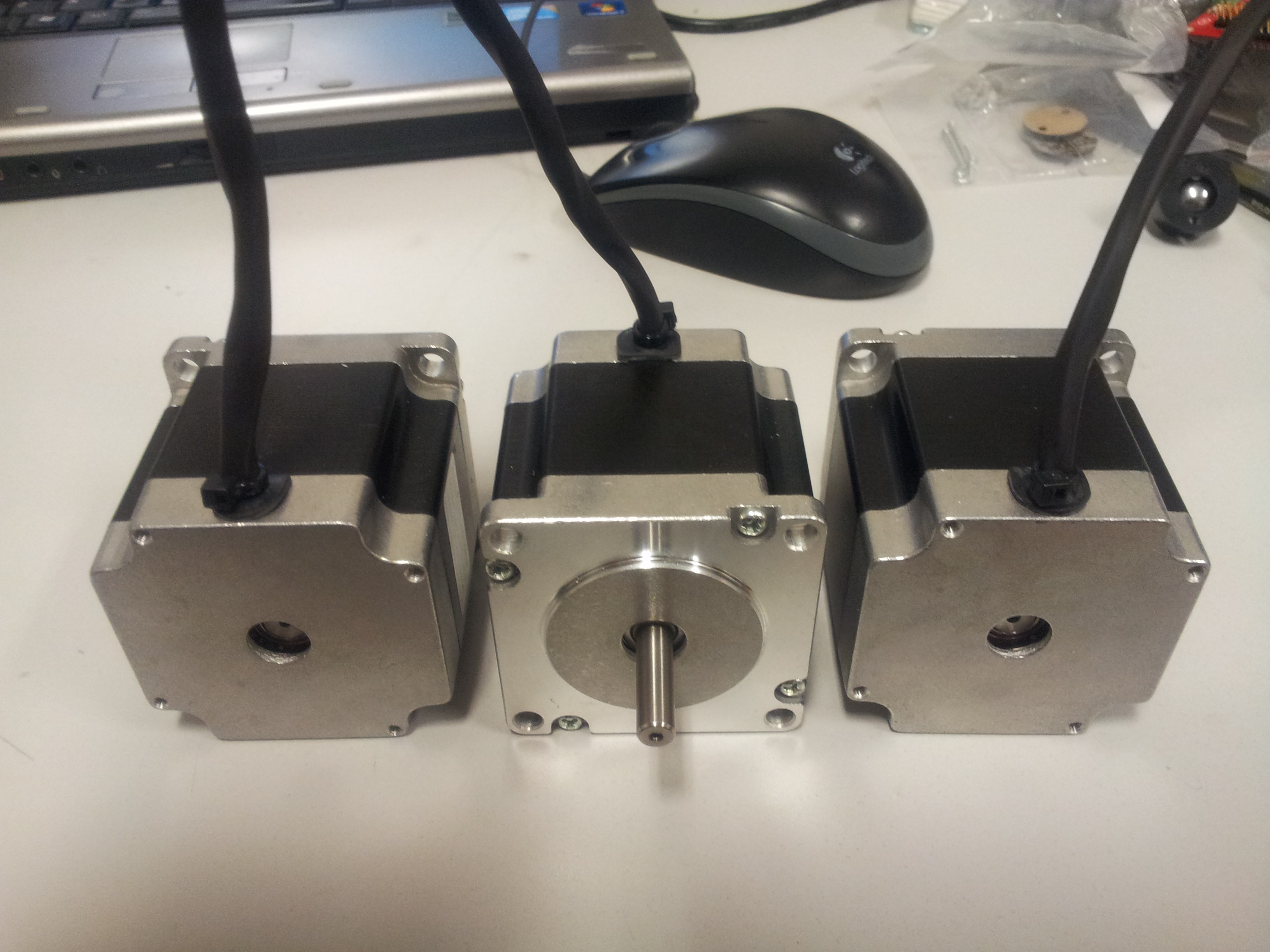
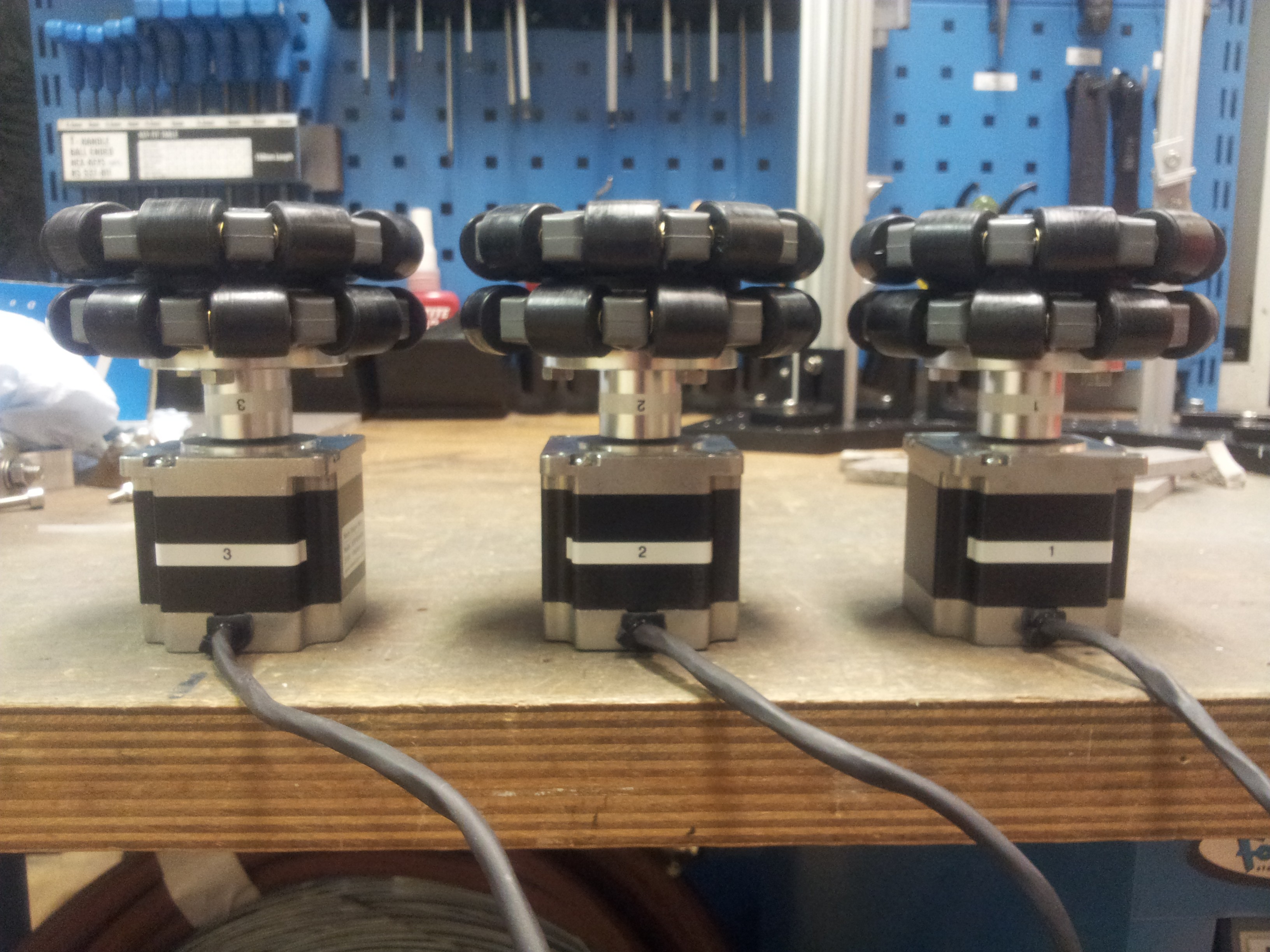
The spacers were cut to the appropriate length using a lathe. The central hole in the wheel hub for the holomonic wheels where also enlarged to 1/4" to accommodate the stepper motor shaft. The wheels were then installed onto the motor shaft.
![]()
![]()
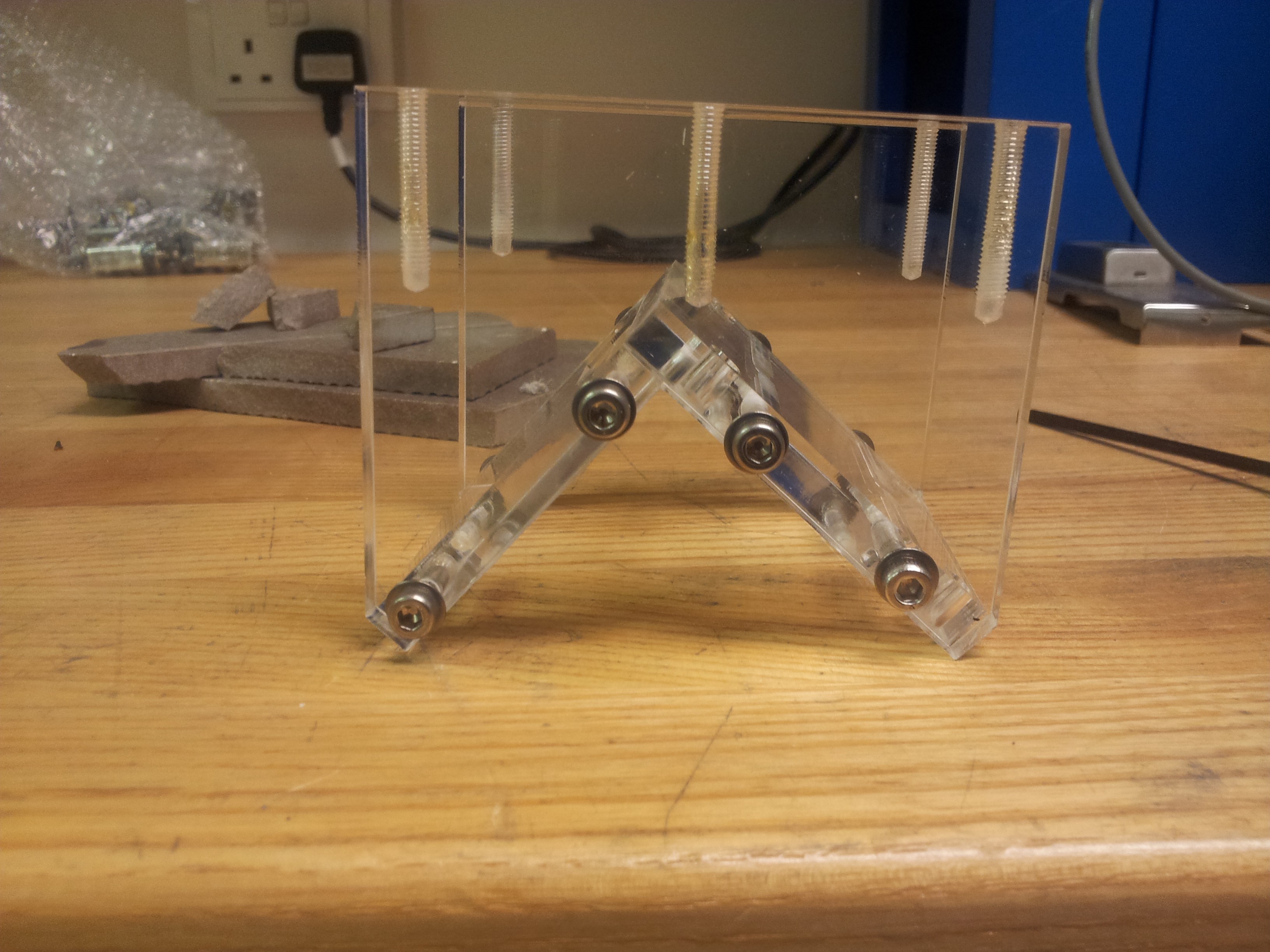
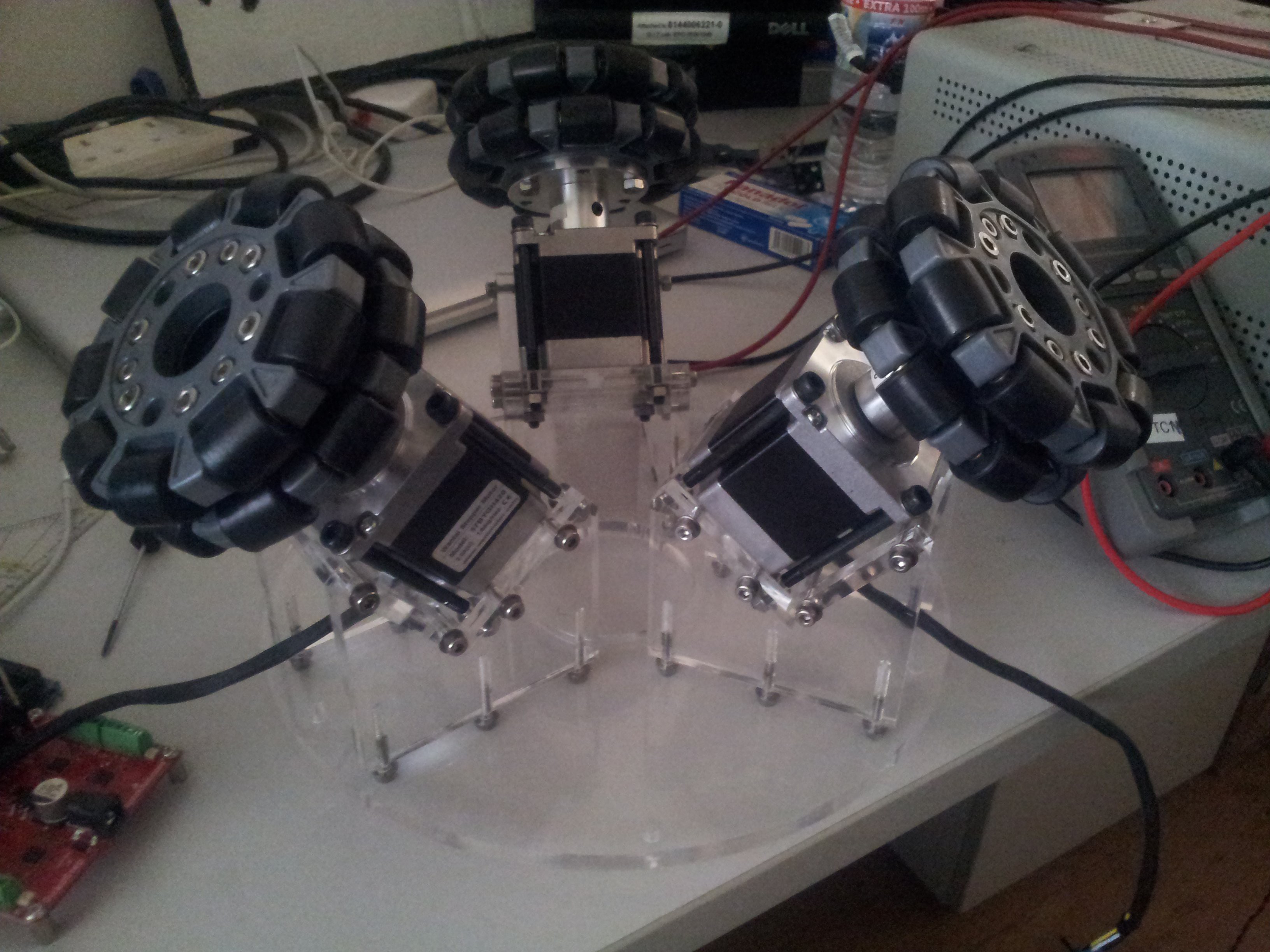
Finally all the parts were assembled.
![]()
![]()
-
Ball Balancing Test Base Concept
08/17/2015 at 15:12 • 0 commentsAs we have no experience at all at building a balancing robot of any kind, it is prudent that we build a test base for this purpose. The design we have can be found here:
The structure will will consist of 8mm thick laser cut acrylic. Laser cutting is the fastest and most economical prototyping means available to us. The holomonic wheels engages the bowling ball at an angle of 45 degrees, midway between the pole and equator of the ball.
![]() Plates which are about 260mm in diameter are being held together by 10mm diameter spacers made of acrylic rods. Driver and balancing electronics will be mounted on the plate just on top of the stepper motors to minimize cable length. The battery which constitutes a bulk of the weight will be mounted high up for stability (akin to the configuration of an inverted pendulum). We will be using inexpensive Pd acid battery in the beginning which will probably be switched to LiPo in the future.
Plates which are about 260mm in diameter are being held together by 10mm diameter spacers made of acrylic rods. Driver and balancing electronics will be mounted on the plate just on top of the stepper motors to minimize cable length. The battery which constitutes a bulk of the weight will be mounted high up for stability (akin to the configuration of an inverted pendulum). We will be using inexpensive Pd acid battery in the beginning which will probably be switched to LiPo in the future.
OSCAR: Omni Service Cooperative Assistant Robot
A project aimed at developing a humanoid ballbot platform.


 The corridor was in fact straight. The fact that it appears curved here was possibly due to the fact that the wall on that side was exceptionally featureless. So the Hector SLAM algorithm may not be matching up the features accurately. Maybe implementation of the odometry input would help in this case.
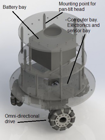


 Plates which are about 260mm in diameter are being held together by 10mm diameter spacers made of acrylic rods. Driver and balancing electronics will be mounted on the plate just on top of the stepper motors to minimize cable length. The battery which constitutes a bulk of the weight will be mounted high up for stability (akin to the configuration of an inverted pendulum). We will be using inexpensive Pd acid battery in the beginning which will probably be switched to LiPo in the future.