256byteram
-
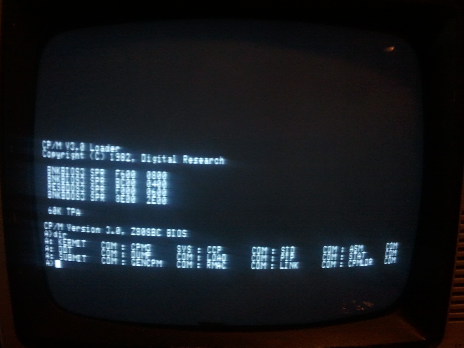
CP/M Plus (finally) booted
07/17/2014 at 11:44 • 4 commentsOkay so it has been quite some time since I've provided an update. I've got good news however. I have at long last got CP/M Plus to boot correctly on my hardware and got it to use bank switched memory.
The disk access speed improvements are significant. That and it's capable of accessing partitions up to 512MB, much more than CP/M 2.2's 8MB limit.
Here are some things I learned about CP/M Plus:
- Digital Research implemented a serial number scheme, where if any of them don't match, the OS will halt. Make sure all binaries come from the same distribution.
- Get it working without bank switched memory first. Even if this means it's working with 34kB free, at least it's working.
- Make sure Disk Parameter Headers and Disk Parameter Blocks are sane. There should be a few vectors before the DPH to tell the BIOS where your routines are. Check the manual.
- Make sure you're selecting the correct bank when reading or writing to the disk.
- The Z80 reserves Reset Vector 0x38 as an interrupt vector (when using Interrupt Mode 1). This causes a lot of incompatibilities with the default CP/M debugger as it uses the same vector as a breakpoint. Use patched copies.
- Place interrupt vectors on all banks when booting and make sure to say the bank starts at page 1 (not page 0) so the BDOS doesn't use it as a buffer.
- If it's not working, it's your fault.
I'll add more as I think of them.
In the meantime, please enjoy this picture:
![]()
-
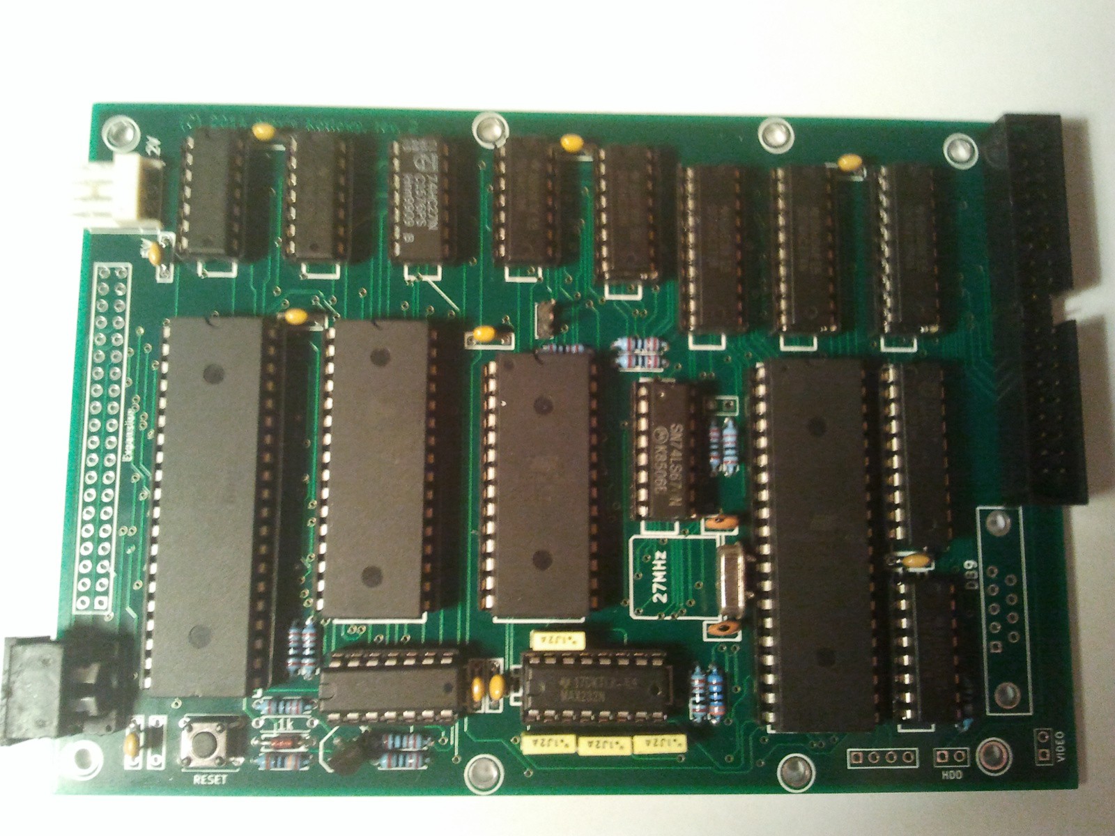
PCB's arrived and work!
03/29/2014 at 08:05 • 8 commentsThe PCB's have arrived. I assembled one and it worked beautifully. I've got 12 PCB's in total. If there's enough interest I'll have more manufactured.
![]()
One problem however - the DE-9 connector is just a little bit too close to the IDE connector. It fits but you need to shove it, or sand it back a little. I'm not happy with the video output connector either. It needs an RCA socket of some sort, but there's no room.
-
PAL Colour
02/21/2014 at 10:49 • 0 commentsI've taken a break from CP/M Plus for the time being so I don't lose interest in the project. I'm currently looking at implementing a colour graphics overlay board. Presently, the colour is generated by an ATmega164P, a 74HC74 flip flop and a 74HC08 quad AND gate. I'm using another ATmega for the time being to make sure the theory works in practice. The ATmega is clocked with a 17.7MHz crystal. This is a standard frequency that is exactly 4 times the frequency of the PAL subcarrier (4433618.75Hz - notice how the frequency is accurate to a quarter of a Hertz).
The 74HC74 is configured to give four 4.43MHz outputs from the 17.7MHz clock, one each at 0
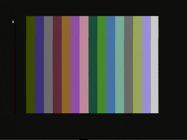
°, 90 °, 180 ° and 270 ° . To encode the different colours, it's just a matter of enabling any combination of these frequencies into the video output with the AND gates, then through resistors to combine them. A small 'colour burst' must also be present just after the synchronisation pulse. The ATmega controls when any of these phases are enabled onto the video output. There are four phases, so there are four pins used on the ATmega to enable them, giving a total of sixteen colours. There is a fifth pin which puts some grey into the visible video as well. Without it, some of the colours would sit below the black level. ![]()
This is a capture of the colours the PAL generator can produce. The dot crawl is made worse by the ATmega's interrupt jitter, which can't be removed because I'm using a hardware interrupt pin to synchronise to. Not a timer. I won't be using an ATmega in the final version, so the jitter will go with it.
The asterisk in the corner is the prompt for the ROM monitor. The 80 column text is mixed resistively with the colour background, and because the dot clock for the text is completely different to the colour carrier (13.5MHz compared to 4.43MHz) there is virtually no colour generated around the characters. The text is a little brighter than the colours and is quite visible. This is why the main ATmega is clocked at 27MHz. It is an exact multiple of the NTSC and PAL line frequencies. To add colour, I just need to mix the colour frequency with the existing signal. I'll make an NTSC implementation later, which shouldn't be difficult (he says...).
PAL is based on the NTSC and adds to it, to try and remove the hue errors that are generated during broadcast. The problem arises when slight phase distortions are present in the signal, and because NTSC has no way to cancel these out, the television receiver displays them as incorrect hues on the screen. This is where NTSC gets the "Never The Same Colour" acronym from (the acronym is actually National Television Standards Committee). PAL's fix to this problem is to invert the phase of one of the colour components present in the signal every other line, hence the name "Phase Alternating Line". The previous line is stored in a delay line and is combined with the present line. If there are phase errors between lines, they cancel themselves, which results in reduced saturation. This is much less noticeable than the colour changing.
This extra complication needs to be taken into account when designing a PAL encoder. At first when I got colour on the screen it was running in "NTSC4" mode, which is used on some DVD players. This is somewhere between PAL, where the colour frequency is 4.43MHz, and NTSC, where there is no phase swapping between lines. The colours would appear on my newish television which supported the standard, but not on my Commodore monitor which only supports regular PAL.
The ATmega has four bits on a port which controls which colour frequencies are enabled. There is also a register which stores the current number to send to the port for the colour burst frequency. This register has the two bits which control the red component inverted every line, using the XOR function. This introduces the 180
° phase shift which the PAL standard uses. Commodore monitor displayed colour with this configuration. However, there was only blue and yellow. These are the colours generated by the blue component of the signal. The problem was I needed to invert the red component every line as well. If it isn't inverted, the same phase of the red signal between lines gets cancelled by the delay line. That is, the saturation is reduced, to the point where there isn't any. It's not as simple as XORing the numbers being sent to the port. What needs to happen is the two bits which control the red component's output need to be swapped.
I solved this with two lookup tables, for now. The pointer alternates between the two tables every other line. When I make a 'real' hardware implementation it'll be easier to do with discrete logic.
I'm aiming to have a 320x200 pixel display with sixteen colours per pixel. This will require 32kB of static memory. The Z80SBC can address 256kB in total with bank switching, so the extra video memory can be switched in to be written to.
Update: I have made a short video of the board in action.
-
Bringing up CP/M Plus
02/15/2014 at 05:57 • 1 commentI've been working all week to try and get CP/M Plus (aka CP/M 3) to boot on the Z80 system. Compared to CP/M 2.2, it's much more complicated due to the large number of features that were added. I could stick to just running CP/M 2.2, but then there would be 64kB of RAM (of the 128kB total) that would go to waste on the basic system because 2.2 doesn't implement bank switching. I'd also like to make an expansion board with the necessary hardware to run MP/M-II - the multitasking CP/M - which CP/M Plus is based on.
CP/M 2.2 was quite straight forward to bring up because the system components are very linear in the memory map. There are three modules in CP/M - the CCP (Console Command Processor), the BDOS (Basic Disk Operating System) and the BIOS (Basic Input/Output System). In CP/M 2.2, the three modules are loaded as one sequential block from the first track of the storage medium and dumped to the top of RAM. This makes the system less flexible but very easy to implement.
Say if you change the amount of RAM in your system, you would have to relocate the whole of CP/M to a new memory location and update all of your boot disks with the new version. Chances are you would also have to change the boot sector to load everything to the correct address too. The same goes if you change your system configuration, i.e. higher capacity storage, new peripherals, etc. You need to add the changes to your BIOS, reassemble, relink and update any boot disks.
CP/M 3, being quite advanced for the time, solves these problems to some degree by having a four stage boot process before you get to the command prompt. First the system ROM loads the first sector of the first track of the disk storage and executes it. This loads in a small program called CPMLDR.COM from the first track and executes it. CPMLDR.COM contains a minimal implementation of CP/M Plus and a BIOS. This loads the file CPM3.SYS off the file system to the correct location in memory and executes it. The system is then initialized by CPM3.SYS, vectors set and so on, then CCP.COM is loaded into the program area and executed, giving you the command prompt. It is done this way so the operating system code is in a file, not on the boot track, which makes the task of updating or patching it a little easier.
Given the system is so complicated, if there is anything even resembling a bug in the boot procedure or CPM3.SYS, the system will crash. This is the problem I've been having as I'm not exactly the best coder out there.
My first problem was trying to read the existing CP/M 2.2 file system at all. That was down to CP/M Plus using slightly different parameters to 2.2 for defining the disk storage. Then when booting, the system would try to switch to memory bank 2, which doesn't exist, and load CCP.COM to it. Only banks 0 and 1 exist, that is two banks of 48kB plus 16kB of 'common' RAM that doesn't get switched. The bug was in the default boot code. It explicitly switched to bank 2 to load CCP.COM, and copied it to bank 1 to warm boot the system without having to access the disk. No problem, the system doesn't touch most of bank 0 so I'll use that instead. I eventually got it to say "BIOS Err on A: No CCP.COM file" so I transferred CCP.COM to the file system. It still wouldn't boot.
After more stuffing around and some amount of luck I got it to display an A> prompt, but it doesn't respond to interrupts from the ATmega. I'm stuck here. For some reason interrupts don't work. I'm using Interrupt Mode 1 on the Z80, which uses vector 38h to jump to the interrupt routine. CP/M should in theory leave that vector alone unless you're running a debugger. Something is either disabling interrupts or is changing the the vector. I'll keep at it though.
A final note, CP/M was the ubiquitous 8-bit operating system for 8080, 8085 and Z80 business machines of the late 70's and early 80's. MS-DOS might be considered a clone of it. We all know who won out of the two...
Z80 Microcomputer System
A small Z80 computer with composite video, serial and a hard drive with CP/M