Eric Hertz
-
The second "duh-moment" revealed + Interesting Materials!
06/10/2016 at 12:01 • 2 comments(Update 2: Another photo from mirrored-plastics-burning)
(Update: Adding results for potato-chip-bags/"mirrored" plastics)
Alright, the last-log I led-up to this... second "duh-moment" which reduced weeks of over-engineering down to little more than gravity and binder-clips...
As described in the last log, I turned the upper-axis sled/laser mechanism on its side in order to do some experiments with lenses of different focal lengths (and discovered the focal-length of the lens--*under* the drive's adjustable-focussing lens--the one I originally presumed to be a collimating-lens--to be durn-near exactly the focal-length I was looking for (about 10inches). Cool!
But the second discovery came from those experiments and had nothing to do with them... intentionally, anyhow. The second discovery is that the upper axis doesn't have to be "upper" (facing down) at all!
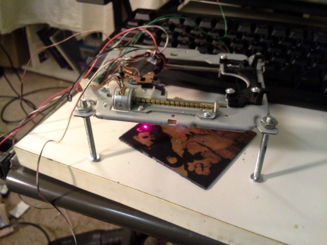
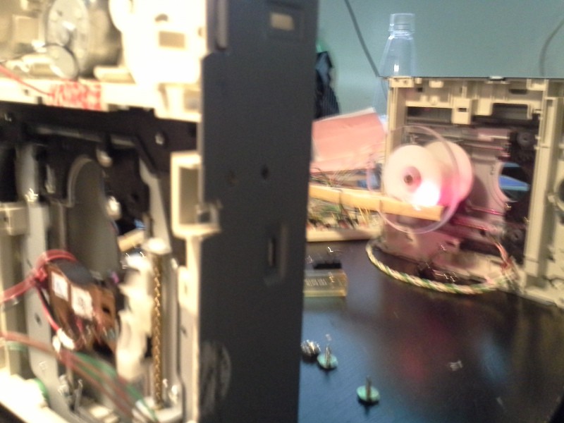
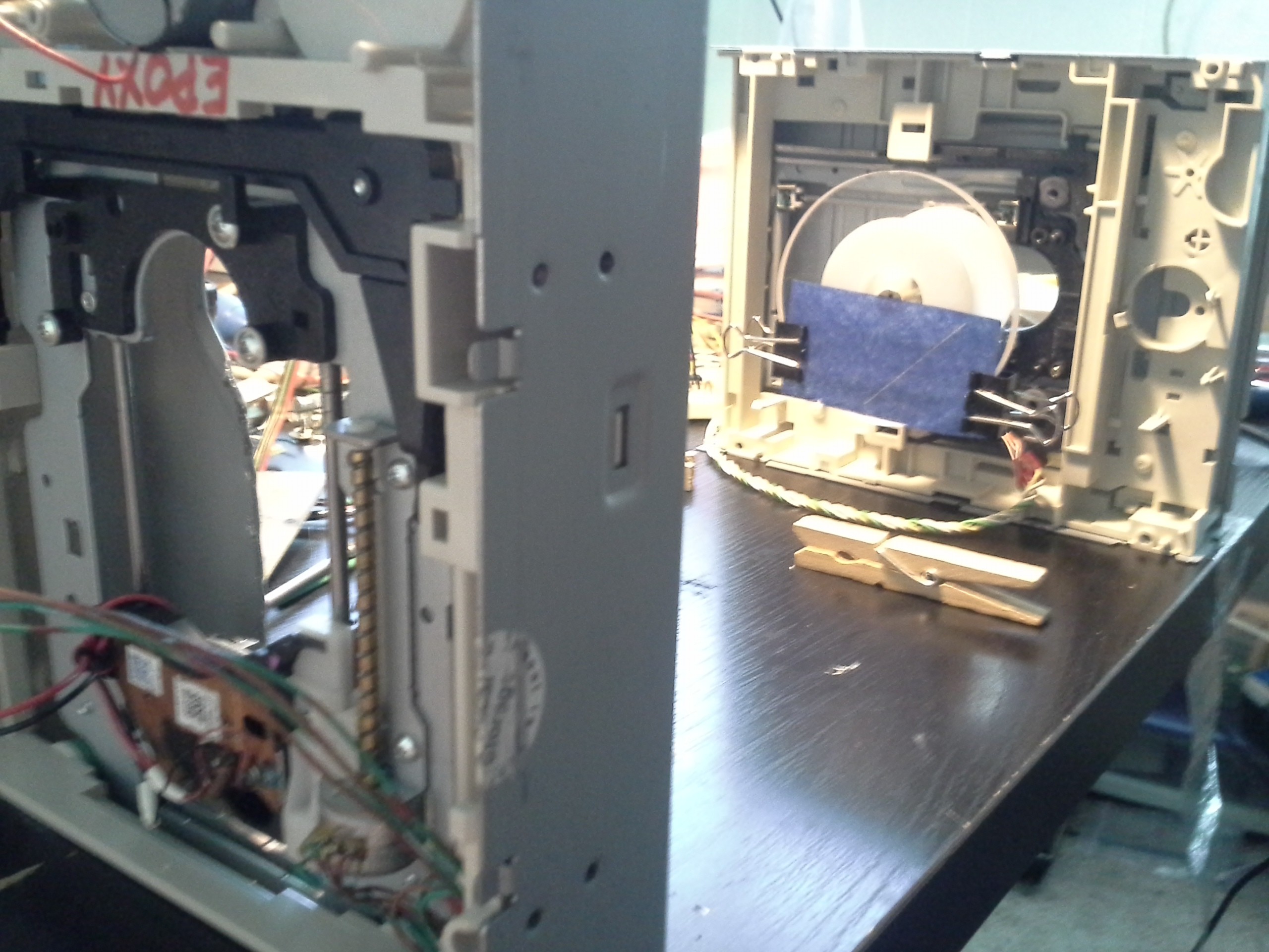
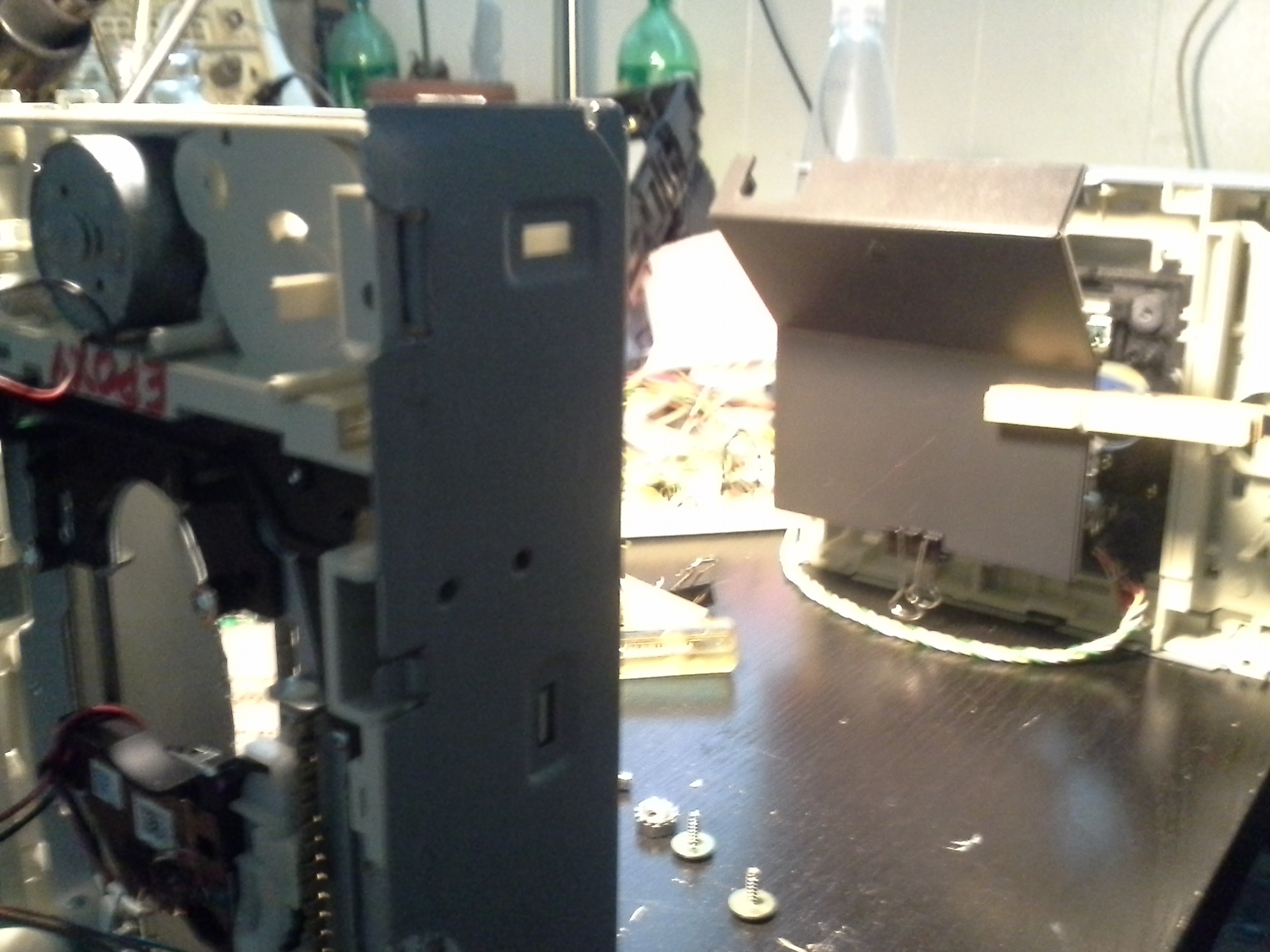
Here's the new setup... it's *way* easier to adjust focus, square, parallel, and much more... And doesn't even require any screw-adjustments to do-so!
![]()
Gravity can be your friend...
The laser/sled axis is the one closest to us... It originally traveled with the laser facing down onto a horizontal surface. Now that surface is upright (why not? We've gotta clamp the material down somehow anyways...)
(Sorry for the blurry image, later images will be more clear, this just happens to be the only one with the laser lasering... And a fore-sorry for the sizes of the following images... I should probably write an imagemagick-script again soon... what's reasonable these days...? 1280x960?)
So, that's the "Big Duh" which reduced quite a bit of mechanical design and failure to... unnecessary.
Now for some results...
We all know "black [electrical] tape" is cuttable with a laser-diode... And there are a few other such materials which just make sense, such as (as I discovered a while back) floppy-disks (the magnetic/media part),
I didn't take a photo, from a while-back (Update added at the end), but another interesting result was cutting *through* potato/corn-chip bags... We're talking the heavy plastic that's *mirror-finished* on the inside. So, cut yourself some mirrors!
I'da sworn that mirror-stuff would've gone all the way through, so all I expected was to burn off the ink on the outside of the bag, leaving a mirror-finish behind the "cut." Instead, the ink apparently sucked up enough heat to even burn through the mirroring. COOL. (even weirder, it seemed to work perfectly fine with *red* bags, which I'd've expected to be *reflecting* the laser-diode's red color...)
Here are some more recent results, some quite surprising, as well...
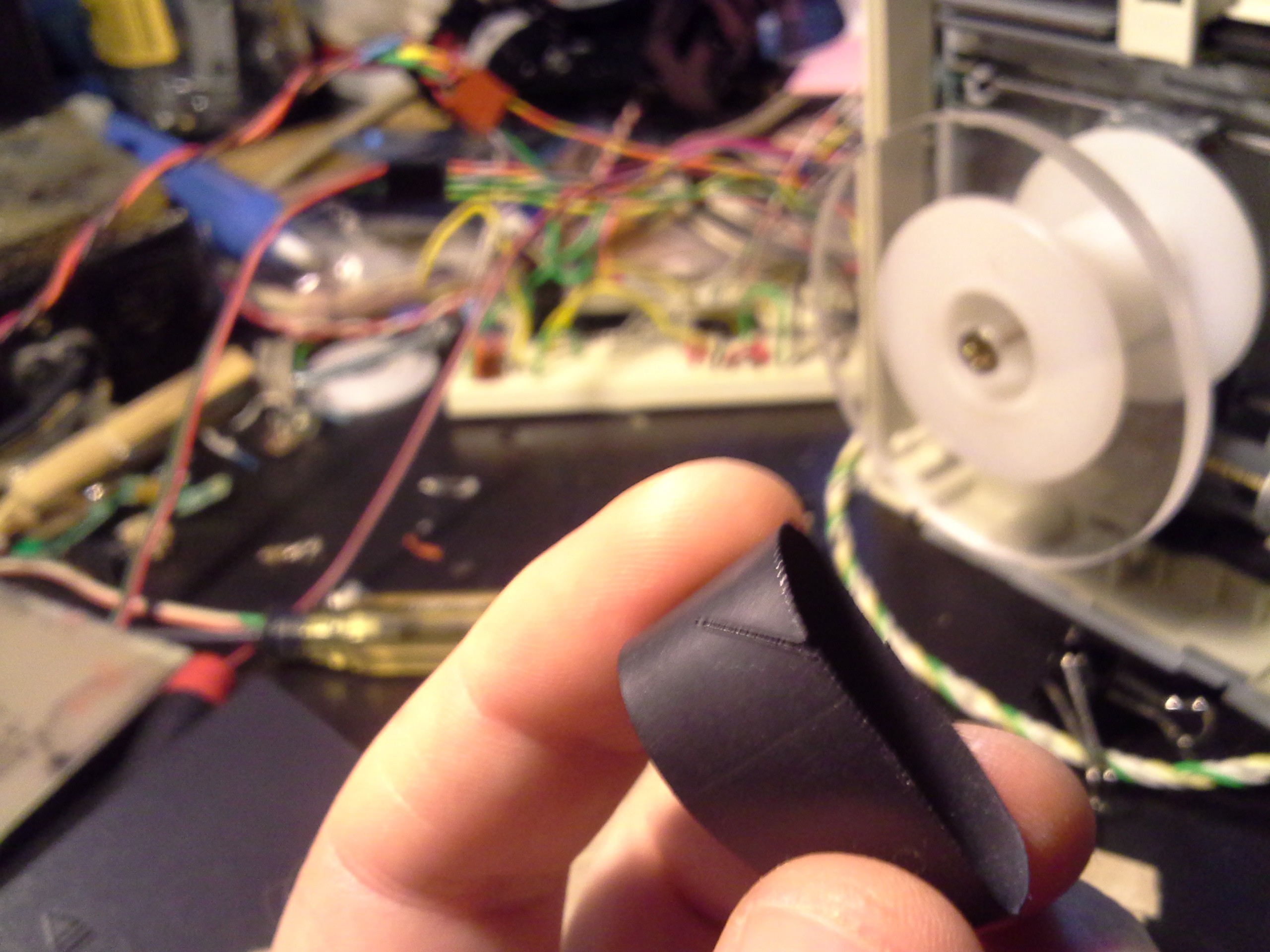
Colored Tissue Paper:
![]()
(Note the diagonal line... that same pattern used in all the experiments)
This pretty much cut completely through the paper, except in a few places where it left some white fibers... Maybe the ink isn't consistent... and obviously the thickness isn't, as it can clearly be seen-through in several spots and not at all in others).
(Would it work with Construction-Paper?)
Etch Plastic... (This one's in the "expected" category, as I'm sure we've all seen people've etched their names on their cell-phones...)
![]()
This happens to be a back-cover from an LCD monitor. Seems to work best on Matte-finished plastics, *really smooth-finished/shiny* plastics not-so-much. Though, it probably has to do with the actual type of plastic as well...
But this one was a shocker to me...
Burn/Etch Wood!
![]()
I figured it wouldn't work, because it doesn't do anything to light-colored paper... I even tried (pink) carbon-paper and (white) thermal-paper with zero-results. But here's a very-light-colored *wood* that burnt darn-near perfectly.
That led me to a strange conclusion... Maybe bleaching has something to do with why it doesn't do anything to paper...(?) So, I thought I'd try some unbleached paper...
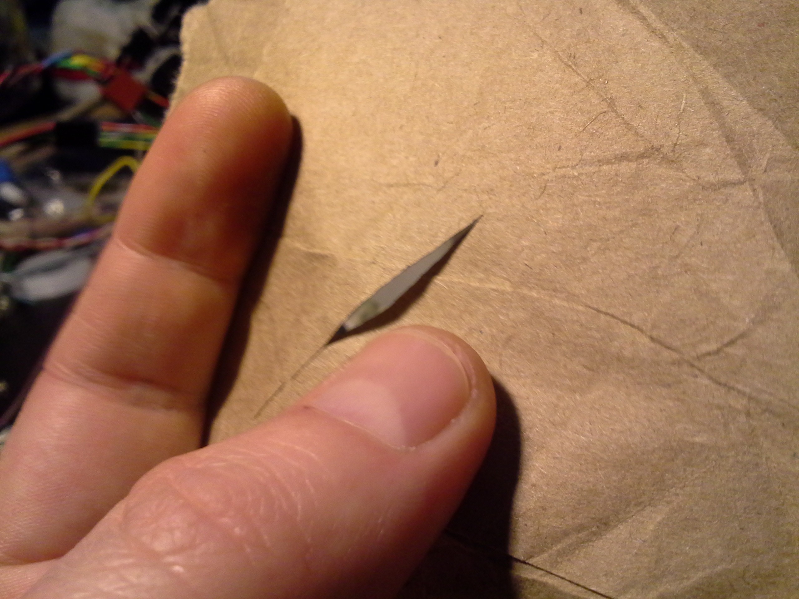
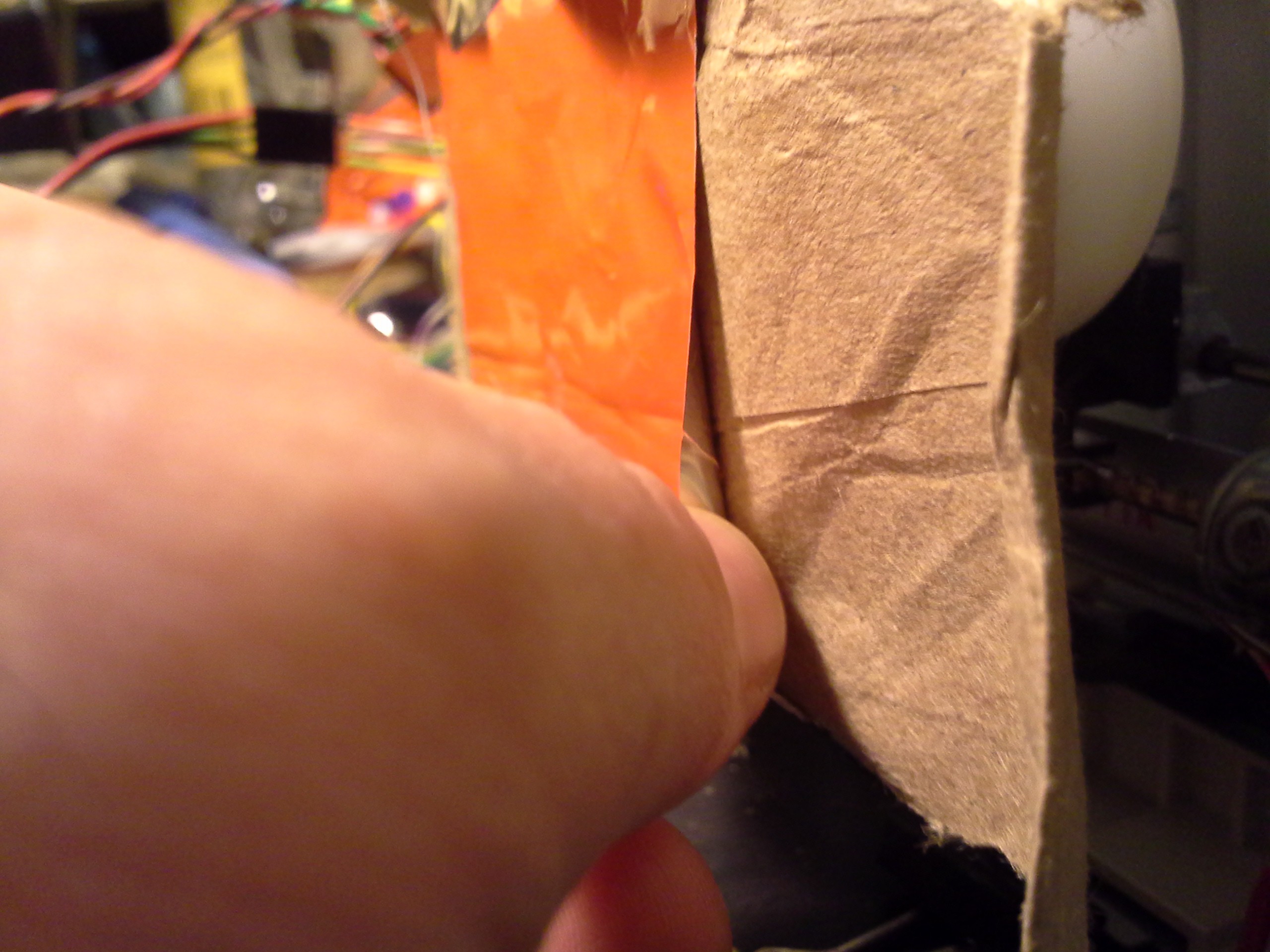
Paper Bags.
![]()
I thought it just burned like the wood, until I picked it up... nope, it cut right through.
Etch Corrugated Cardboard?
(Use during calibration-experiments!)
So, I think maybe corrugated cardboard is the next experiment... I figure if it burns wood and cuts paper-bags, and cardboard is kinda like several layers of paper-bag material... we should get some burning... (Maybe even the unbleached card-stock-ish material used in e.g. cereal-boxes).
In which case, that'd be a pretty decent (and obviously cheap/easy) material to run experiments in calibrating software, etc... (Which would be quite handy for, e.g., fine-tuning/test-running the setup for double-sided printing on the #Mini PCB printer).
Heat Shrink... (and wire-labels?)
No idea what I was expecting, exactly, but I kinda visualized the possibility to etch labels into heatshrink before shrinking it... (Yahknow "GND" "5V"...)
![]()
![]()
That one... would probably take some fine-tuning. This particular heatshrink is obviously quite large, and also thick, and it didn't burn-through, but it did definitely weaken it at the burn... Heat that up (for shrinkage) too much around the "label" and it'll likely just rip apart. But feasible...
I have no idea what the laser's actually doing to the tubing, though... Is it plausible the heat is just causing it to "shrink" locally, rather than actually *melting* it...? (It would seem shocking that the laser's heat-output would be higher than the tubing's ability to withstand my friggin' heat-gun which can melt solder...) And, I could be mistaken, but beside the "etch" it almost seems like the heat caused it to shrink just a little bit, forming a ridge... Interesting, but no idea what it'd be useful for.
These experiments were done with the laser-diode from a 20x DVD drive, as I recall... And, again as I recall, the maximum-output of my LM317-based current-source is 250mA.
And if you didn't pick up on the obvious bit that took quite some time for me to pick-up on, leave those sleds in the drives' housings; it sure makes for easy "assembly" using just gravity and a work-bench/table/floor.
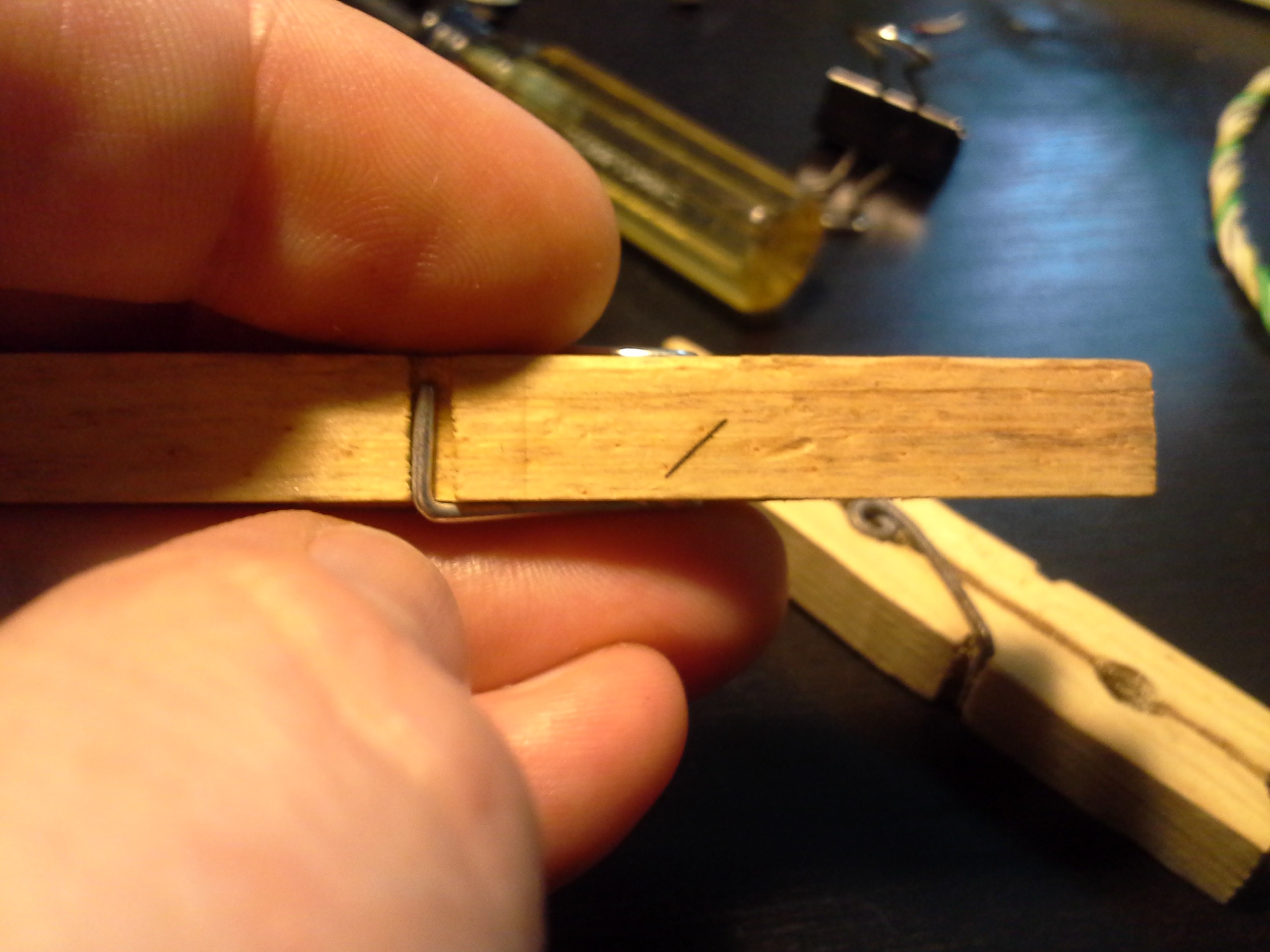
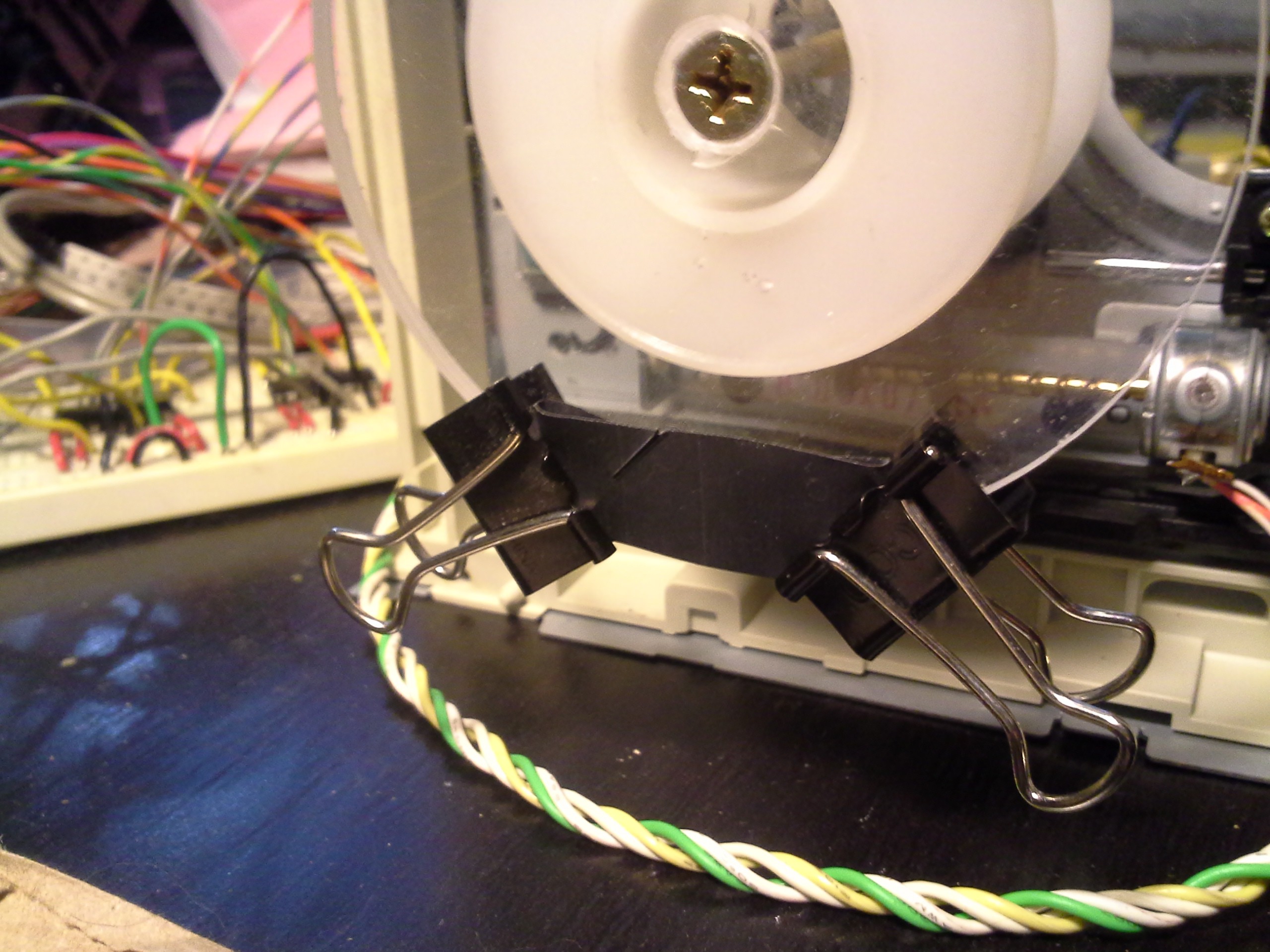
And if you're as prone to over-engineering as I am, then here's another tidbit, from @johnowhitaker: It's easy to make fine-adjustments using little more than stacks of paper as shims... Books, post-its, who knows.... Still getting phone-books, dunno what to do with 'em? rip to the right thickness... Oh, and another one, also from johnowhitaker: Use binder-clips (or clothespins, since binder-clips were at the bottom of the same box) to secure your material... WAY easier than, say, designing (and cutting) a special bolt-pattern... (Something like that can always be added later *if necessary*).
Finally, look back at that last log, I was pretty excited about a few things there, but one of the "big ones" that I'll be adding to my tricks-of-the-trade is the ability to use wood-screws with those stamped-sheet-metal "nuts"... That's what's holding my work-surface to its sled, and works *way better* than I would've ever expected.
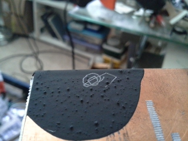
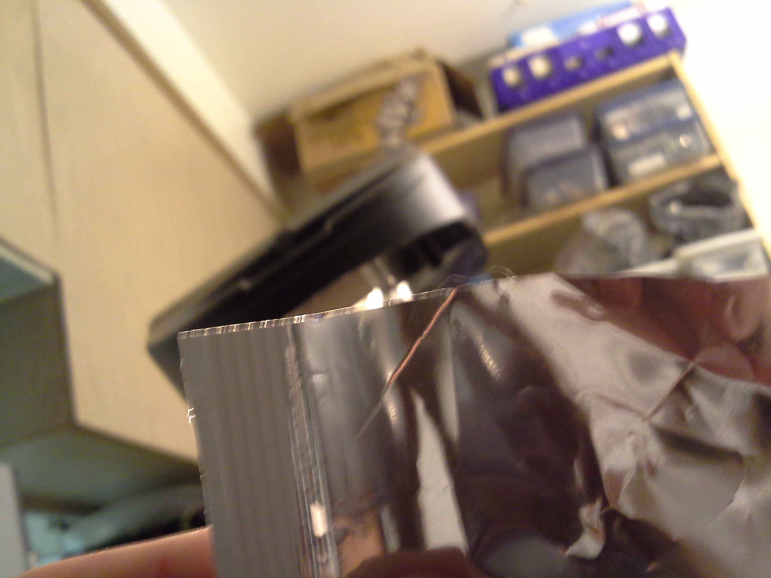
Update regarding potato-chip bags...
This is a different brand, but has that same mirrored-finish on the inside. As I recall from my previous experiment, it actually *cut* that bag, but this one just seems to have burnt away the "ink" including the mirror-finish, but the bag itself seems intact (and clear). Could be interesting...
Very hard to see the path, above, but you can see how it burnt through the mirror-finish on the other side...![]()
![]()
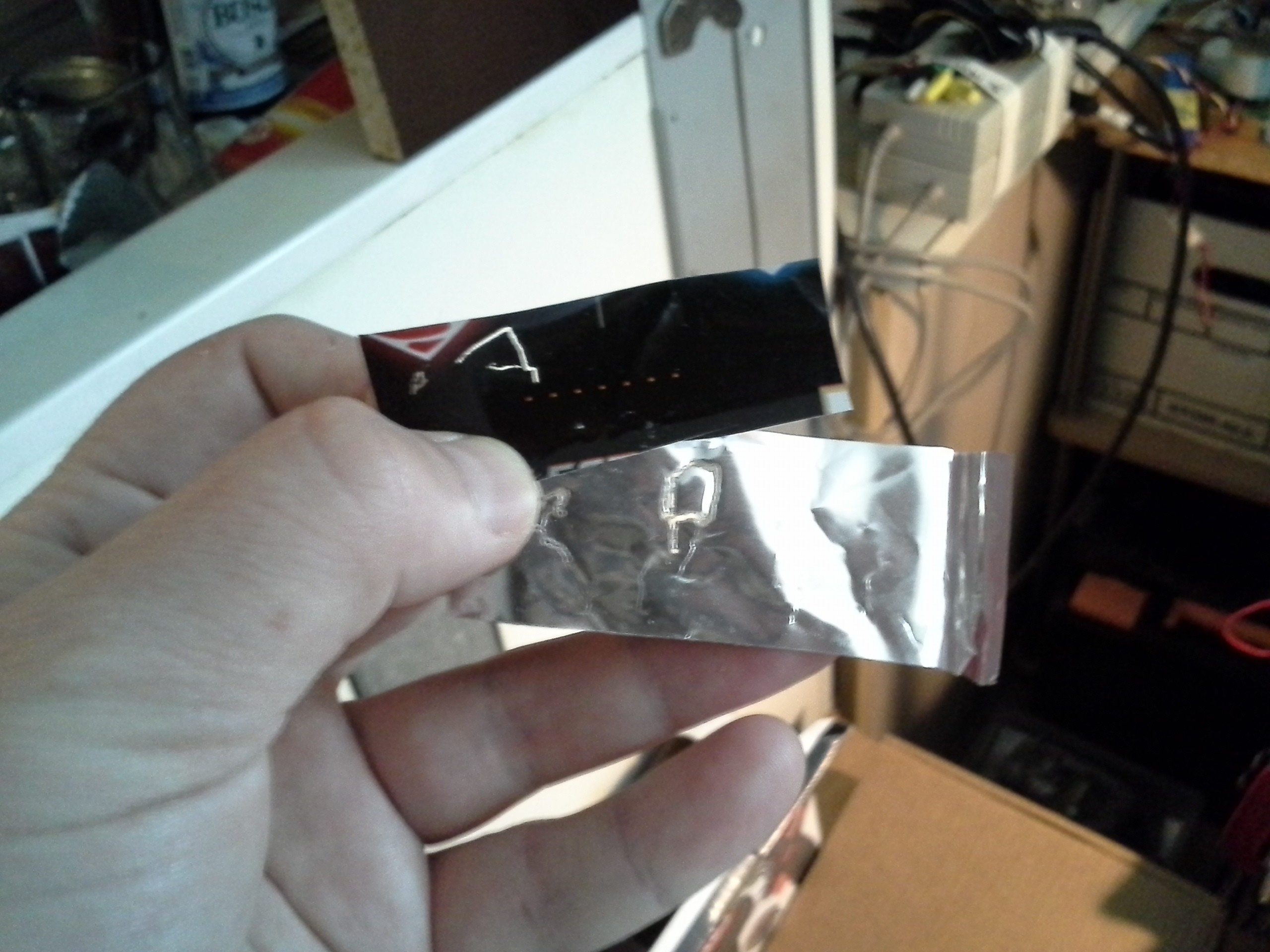
(Actually, upon looking at it more closely, it almost looks as though the orange ink is still on the other side... Interesting).![]()
The material is a little weakened where it was etched, as in it wants to fold down that line, but trying to rip it takes some effort, so there's definitely a bit of "clear" material left-over...
Hah, apparently I had a photo on my camera from the first-run... This bag was mostly-red with some black on it. Among other surprises, the red burnt through, as well.
![]()
-
2-axis "duh-moment"
06/08/2016 at 08:52 • 0 commentsI'mma keep working on this, pictures/explanation to come later...
But let's just say I had a major "duh" moment... And I think the results will be quite a bit easier for most 2-axis systems.
It wasn't an *easy* duh-moment... In fact, it was the result of many iterations of over-engineering-reduction. And, by "reduction" I mean... extra-engineering to accommodate flaws in said-over-engineering to the point that it got completely unwieldy and eventually that "duh-moment" *finally* struck...
No, not even then, actually... In fact, if I gotta get my facts straight, the "duh-moment" was the result of something entirely different, *after* all that over-engineering got in the way, then was "reduced" (which, again, means that it was actually even more over-engineered, until it was too much to bare... But Even Then, I didn't see the obvious duh-moment... until giving up on that and beginning to deal with an entirely different aspect deserving of "duh" as well.).
So, actually... *TWO* "duh-moments".
I'll tell of the latter...
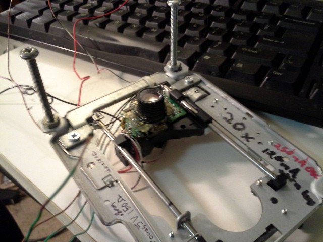
The latter being: The laser-output of the DVD-sled, once the focussing-lens is removed, appears *mostly* collimated... It's not perfect... It comes out of the under/stationary-lens as a circle about 1/4in-1/2in wide... And when it hits the ceiling it's something more like 2in... So, kinda collimated, but not perfect. That guy, I fed into a regular-ol' lens with a reasonable-enough focal length (about 2in), which meant that I had about 2 inches between the laser-sled and the work-surface... Which seemed like a lot a while back, but turns out is not that much space to work within (making adjustments of the work-surface, etc...). Additionally, it means that the beam widens somewhat dramatically with only a few mm of distance-change...
OK, so... I had the thing set-up with a "shield" surrounding it, so it wouldn't blind people... And then I had the brilliant idea to try out different lenses... maybe I'd find one with a more reasonable focal-length (yahknow, maybe 6-8in?). That'd give more space to work within, as well as making the focus less-susceptible to minor error due to, say, the two axes not being perfectly parallel...
Right, so I removed the lens I hot-glued in a while back... And I turned the thing on its side (as opposed to facing down onto the table, as it was designed to be run) so I could do focussing-experiments...
And turned it on (with LOW POWER, BE CAREFUL WITH YOUR ONE-REMAINING EYE!), and started to play around with different lenses...
And only after playing around with a new lens for quite some time--and not able to get it to focus on the "shield"--did I realize... wait a minute... What the Heck am I looking at...? That's not a 1/2in beam hitting that shield (when the lens is removed)... It's a friggin' dot. It's, in fact, a highly-focussed dot... shining on some arbitrarily-placed cardboard a good 10-12in away.
The Friggin' "poorly-collimated" beam doesn't splay outward from the friggin' lens--1/4in at the bottom and 2in at the ceiling--it has a friggin' focal distance about 12in away.
Which, frankly, is downright perfect.
(Hey, yahknow, there's HaD-FAILs... but no HaD-DUHs? Hmmm...)
So, we don't need an additional lens, at all, *and* the other "duh-moment" came from this exact procedure/experience, as well, but I'mma save that for later...
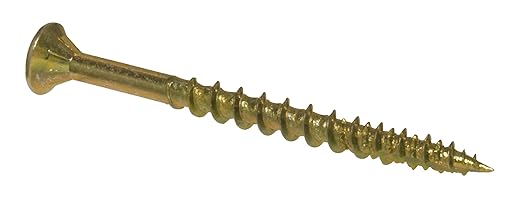
Oh, and another "duh-moment"... I couldn't find a tapered-head bolt long enough for my needs... So...
One of these...
![]() Combined with one of these...
Combined with one of these...![]()
(not my images)
... actually works *way better* than I'd've ever expected.
-
Current Measurement FAIL!
06/04/2016 at 21:26 • 0 commentsDon't use wire-wound resistors in current-measurements with oscilloscopes and PWM... Seriously, just don't.
Took something like an hour to figure out that was the cause... Weee!
-
Jerky Steppers... and underspec'd drivers.
06/04/2016 at 21:18 • 0 commentsSo, I'm finally back, getting into the groove of this ol' project...
Numero Uno: The code works, still, *Woot!*. Took a little bit of cleanup, and had to parse/rewrite some poor-documentation to get the pinouts right...
But... I have two axes running. Two DVD-sled axes... This revisit is spurred-on by #Mini PCB printer.
So, here's the weird thing... I did some math, right...? And if I did the math right, that means there's about 840 "steps" over 1.5inches... which is, roughly, 1.7mil of precision. YET, when I watch these motors do their moving... it's Jittery, to say the least.
Taken a step further, I'm using microstepping which, frankly, should be roughly 512 steps *per* step... so there's dang-near little doubt I shouldn't be able to *see* the stepping-motion. I'm no fool, I realize my "microstepping" technique may not be perfect, and I also am aware of the fact that microsteps are usually quite a bit less precise than regular steps (wherein, e.g., a half-step may not actually be halfway between two full steps, but might lean toward one side more than the other... especially with loading, etc...). But, even *full* steps should be about 1.7mil, so, frankly, I shouldn't be able to *see* it stepping around... right?
Nah, it looks *aweful*.
So, I did a quick test... I switched the axes, by merely changing the wiring... and suddenly that really jerky axis is smooth. And that smooth axis is jerky.
So, there's two possibilities, here... Either A) My code is poorly-implemented on one axis, and not on the other, or B) the driver-chips aren't acting the same....
So, I don't quite get this, because, again, even if the microstepping was *really* bad, and even if the driver-chips can't handle microstepping *at all*, they'd still, worst-case, be stepping somewhere around 1.7mil per step. But, yet, it's *easily* visible just how poorly they're stepping...
But, it is what it is.
The fact is, now that "jerky" axis is moving *really smoothly* and hope is restored.
Apparently I just need to get rid of whatever poor driver-chips I've got, and move on. Or, maybe, all it'll take is slowing the PWM frequency a bit...
Seriously, though... I mean, the jerkiness was *easily* enough to destroy layouts for, say, a TQFP... When I did the calcs I thought "Oh, 0.0017... that must be 17mils... Yeah, that's about the jerkiness I'd seen..." No, that's 0.0017=1.7mils per step. Per STEP (not microstep). So... it's *really* weird.
But, then, what isn't these days...?
Carrying on...
If this 1.7mils/step is true, then there's really no reason for microstepping at all. At least positioning-wise. OTOH, the *act* of microstepping from one step to the next allows for (or at least seems to) *much* greater torque during the transition from one step to the next... So that's something...
Then there's *heat*...
The motors are DANGED HOT... I'm using 12V to drive 'em, which may be the problem... But 5V isn't enough to move 'em... So, realistically, maybe I should be using a more... sophisticated... approach.
A) These motor-drivers (from old floppy-drives!) have two settings... a low-power mode, which holds the motors with 5V, and a "seek" mode, which uses 12V... So maybe I should start considering that...
B) If microstepping isn't gaining *any* (necessary) positional benefit... (e.g. if it really is 1.7mils/step) then the only benefit of microstepping is to apply quite a bit of power *during* the transition from one step to the next... which will certainly help missed-steps, but should probably be avoided for actual *positions*...
OTOH, if doing something like PCB artwork, we're not talking about *briefly* moving a motor to a position and holding it there, we're talking about *constantly* moving the motors to draw various traces... So... Hmmm...
I kinda miss the ol' DC-motor (and feedback-loop) approach... At least, there, only the amount of power *necessary* to hold/move it is applied... In a case like this, "holding" a position requires almost *zero* power, whereas moving it might require a bit, but probably not nearly as much as a stepper... (wherein the stepper must apply enough power to compensate for *any* load it may encounter, as opposed to the actual load it is encountering).
So... I guess the question is how to determine when it's acceptable to lower the voltage...
---------------
All that written before I figured out the problem... the stepper-driver chip that caused the jerkiness was (likely) spec'd for a lower current and was clipping the current. But, only at certain PWM-duty-cycles. So, I think, what was happening was it was somewhere midway between steps, then suddenly the power was cut (on only one winding) and the stepper would jerk to the next (or previous?) step, then the current-clipping would be disabled (as the PWM duty-cycle changed) and it'd jump back again to somewhere midway between steps. Taken a step further, the actual "step" it would wind-up in could probably be somewhere *dramatically* different than normal single-stepping because: Only one winding would be powered (whereas normally both windings would be powered either with one polarity or opposites). And, plausibly, it might've been moving forward then jerking backwards and forwards again (making it that much more visible). So, maybe that all makes sense.
It's smooth, now, but REALLY HOT, so that's the next consideration.
-
Use the spindle motor as a positional-encoder
04/09/2016 at 06:13 • 0 comments -
Dampening?
04/09/2016 at 04:48 • 0 commentsInteresting observation (second one I've encountered like this, the first wasn't photographed):
![]()
Notice the second layer of metal, that's not attached to anything except the main mechanism's frame. This one's not the best example, it's got what appear to be screw-holes, but I assure you (as best I recall) they weren't attached to anything. I've another I took apart which didn't have screw-holes. It's just a slab of metal mounted by them rubbery-things and attached to nothing else.
So what's it do? It's can't be particularly structural. It seems to be a weight, I guess, mounted via "springs"... a dampener, I guess. Not unlike the ones mounted atop skyscrapers to prevent sway during wind/earthquakes...? Kinda shocking it'd have *that* much effect as to be justified... What's it dampening, unbalanced discs spinning at high-speed? The stutter of the stepper motors (erm... this one uses a DC-motor, the other had a stepper)? And, think, both the reader-mechanism AND the disc's motor are attached to the drive's frame via much "floppier" rubbery-things... so, if the disc wobbles or the steppers stutter, then *this* dampener's effect is to attempt to keep the overall system more stable while imparting *most* of the wobble into the actual mechansim itself... (?!) So, WRT the drive's housing, the disc and read-head will be inclined to move about quite a bit, no? I don't quite get it.
Ideas?
-
esot.eric's attempt at johnowhitaker's Toner-Lasering Technique... GO!
04/05/2016 at 10:27 • 0 commentsCheck Out @johnowhitaker's new project: #Mini PCB printer, which describes a technique to laser-melt toner directly onto copper-clad board!
If you haven't seen it already, a while-back @johnowhitaker came up with a technique to laser-melt toner directly onto materials such as copper-clad board, and was cool-enough to share it here first!
NOW, he's started a prize-entry/project-page! See: #Mini PCB printer Seriously, check it out!
----------------
(I was originally going to publish this, here, but I think it's better over at that project-page... so this is just redundant for my own memory... Again, Check Out #Mini PCB printer)
Here's a log of my (@esot.eric) attempts. Result: VERY PROMISING.
![]()
![]()
See More... Click below!
This is from a 20x DVD-RW drive. The focusing-lens has been removed and this lens hotglued on. This lens is from an old camera, but its focal-length is about the same as a magnifying-glass. In fact, I used a magnifying-glass for my early experiments and only decided to use this one because its size lends itself well to mounting. (In other words, if you've got a magnifying-glass, go ahead and use it!). The result is that the focal-point is an inch or so away from the laser (rather than the original focusing-lens's 1-2mm) making it much easier to focus on the material (in fact, it seems to work fine without adjustment for materials as thin as tissue-paper to as thick as a PCB).![]()
This particular laser I've been running at 250mA reliably. I haven't attempted to go higher. (And, for the above photo, I accidentally wired it backwards. Thank Goodness it didn't blow! My supplies've run out and my graveyard is large!)
-----------------
These attempts are all moved by hand... Now that I've got these VERY PROMISING results, I'm going to rig up an X-Y system soon.
-----------------
Here's an early (failed) experiment.
Note that the laser's path is clearly visible (nice!).![]()
Note also: Do Not Shake the mixture! Stir it carefully so as not to introduce air-bubbles!
@johnowhitaker's formula is: Rubbing Alcohol and Toner. It took a few tries to get the right thickness (and, actually, I'd almost given up before finding it).
I used the butt-end of a pen cap, with a white/clear housing, to stir the mixture. First I poured toner into a margarine tub, then I added a little alcohol while the tub was tilted. The toner didn't mix in entirely, so I kept scooping more in until the thickness was *just enough* to coat the pen-cap (no more!) and still drain off slowly, revealing the color of the pen-cap.
At that point, pour it onto the PCB and drain it off...
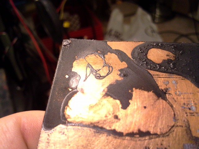
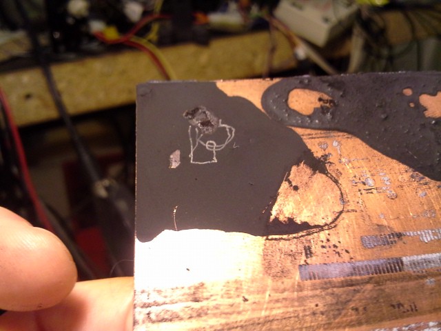
Here's another from the first failed attempt(s):
I drew a "2" (sideways, near the bottom).![]()
The idea is to use a cotton-swab to remove the un-melted toner surrounding the lasered-portion. If the mixture is too thick, it seems to dry like thick paint, and the amount of rubbing necessary to remove it is enough to damage your traces. This one *seemed* to work, but wasn't quite right, and by the time I got it all cleaned up the traces were damaged... here's the lasered-portion for comparison:
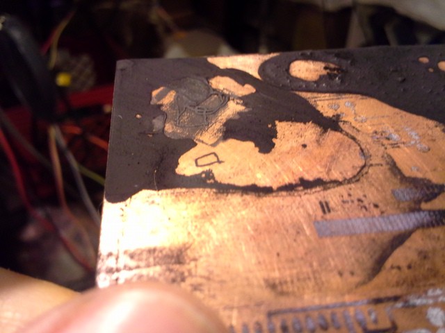
![]()
Note how there was no lasered "cross"-piece... Frustration with trying to remove that and surrounding material ruined the traces.
Note: Don't rub vigorously with the cotton-swab, friction creates heat, heat melts toner.
(For size-comparison, the row of pads on the right are for a compact-flash connector, using the old toner-transfer-paper method, long ago).
Note also: Don't try using alcohol to clean up (until later)... it just rips the traces right up.
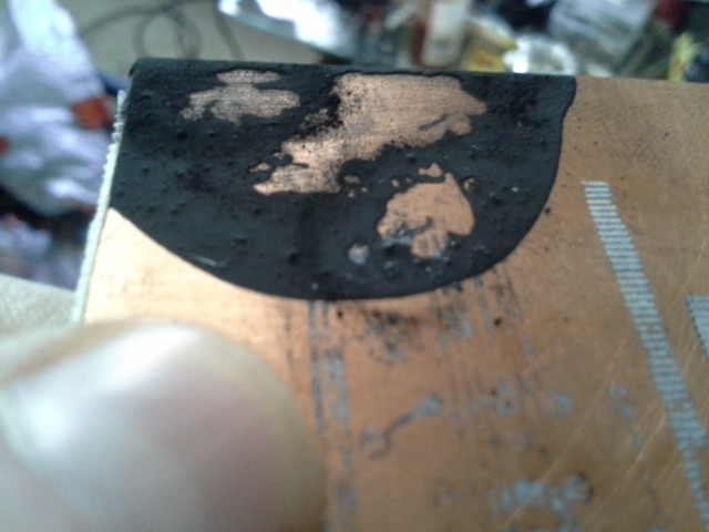
Now for the VERY PROMISING results:
This, again, was with it *just* thick enough to coat the pen-cap while still draining off slowly:
![]()
This is a little bit confusing, I didn't clean the board first, so there's a patch of permanent-marker near the corner interfering with the toner and traces... This was a handy unintentional experiment, too... I'll talk about that later.
I also added a square later-on... Here they are rubbed off with a cotton-swab (note the ugly permanent marker still under the first squiggles).
The traces actually have a bit of heft, almost like... the results of a layer from a 3D "cornstarch-printer" (whoa! hmmmm).
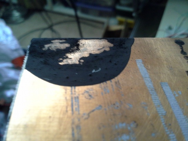
Now here's where that patch of permanent-marker gets interesting... Notice how clean the square turned out, with just some rubbing with a cotton-swab... Cool! It was pretty resilient this time. Awesome. Then I got a bit cocky and decided to try alcohol cleaning, and that square wiped right off.![]()
After that I heated the "squiggled" area with a heat-gun to "set" the traces. Worked well... And then, I tried alcohol again... this time to clean up that permanent marker... and... NO PROBLEM.
Those traces are measuring about 17mils, which is a bit larger than I expected, but perty good for home-made early experiments, no?![]()
Maybe the laser could be better-focussed, maybe the toner flowed a bit when I heated it... I wouldn't put the resolution cap at 17mil, quite yet.![]()
So, some observations... This turned out much better than I expected, especially after those initial failed attempts. I hesitated to rub too hard to clear out the unmelted material between corners and in tight spaces, but I think I could've been more vigorous (or at least more patient) and gotten even better results. Maybe a thinner mixture would work even better. And, one could design boards around these constraints, as well. (or might not even have to). I was thinking to try to avoid things like sharp corners, thinking about material-removal... but then again, where there are sharp corners, there's probably not going to be *another* trace nearby, so even if the excess material isn't removed, it probably wouldn't matter.
And, besides, look again at that detail (WTF? My camera was set to 640x480?!)
Even in the sharp corners it cleaned up pretty good.![]()
Now, as far as resilience for PCB-etching, I think it's pretty much a sure thing. Awesome.
(I'll wait 'till I can actually etch a usable board before trying).
As far as using this method for e.g. creating labels on metal instrument-panels... I'm not sure yet. It can be scratched off, but I didn't try heating it more (and from the bottom?). Clear-coat over the top might be a good idea. Or maybe even a clear pre-treatment under the toner to make it grab better?
Again, Check Out #Mini PCB printer!
-
Other/Unsorted Links
03/20/2016 at 10:56 • 0 comments(4-6-16): Haha! Who'da thunk using optical-drives' mechanisms for steeping tea?
http://hackaday.com/2016/04/06/chaibot-a-tea-robot-steeped-in-utility/
And check out this drive-sled mechanism... what mind-boggler: use a *linear-actuator* to get *rotational* motion, to be converted again into (roughly) linear-motion. Goldberg would be proud. http://hackaday.com/2012/10/22/automate-your-tea-time/
![]()
-------------------
This looks interesting: #BluBEAM - a scanning laser microscope - attempts to use the built-in optics, including the photodiodes...
-
On Laser-Powering
01/12/2016 at 08:26 • 0 commentsCheck out the discussion between @DeepSOIC and @johnowhitaker over at #Mini Laser Cutter, and check out #Measuring DVD-RW laser... two methods for determining how much power to give your laser before burning it out like I did countless times (Update 3-29-16: see below)!
3-29-16: Revisiting this project... it's about time I actually have a 2-axis system like the Mini Laser Cutter, linked above, so maybe I can eventually start toner-lasering some friggin' PCBs!
(OMG, it just occurred to me that once this thing's up and running, I could actually make a PCB to drive it, to replace the breadboarded-system I'd been using!)
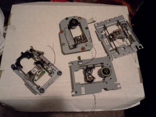
Anyways, one mental-hurdle, which has been taken-care-of in the links above, is that of determining how much power to supply to the laser. I remember having had a "graveyard" of diodes I'd overpowered, but this is the first time I dug through the box in quite a while, and low-and-behold look at this graveyard! I didn't realize I'd killed *that* many!
So, again, this time around I'm going to take a more scientific approach to figuring out how much current to give these things... That is, again, using @DeepSOIC's #Measuring DVD-RW laser.![]()
A great/unrelated trick I'd learned upon rereading that this time 'round: Use batteries (or capacitors) to drive different circuits, that way when you connect your single-ended 'scope probes, it actually can measure across *any* *two* points in the (battery-powered) circuit. It's like using two separate probes in "Additive" mode (with one inverted), or like having a differential-input probe... Awesome!
My next mental-hurdle is in using the DVD-RW's laser (and optics) in a system like @johnowhitaker's #Mini Laser Cutter. He used a separate laser and optics which were more conducive to greater-distances... so I'm not sure whether I'll be removing the focus-lens and replacing it with a different one, or whether it's even possible to use the focus-lens to get more than 1-2mm of distance to the surface I'd like to etch/burn/cut/melt... I think it's a matter of the lens's focal-point, so probably not.
Basically, I guess, I'm just reactivating this part of my brain which's been shut down for a while. *Of Course* the focal-point won't change with-respect-to the focusing-lens... duh. But, now I'm remembering... one of my earlier experiments (in an earlier log) fed the (really wide) collimated output from the drive's optics (with the focussing coils/lens removed) into a regular-ol' magnifying-glass, giving a focal point several inches away AND being of such a shallow angle that slight displacement from the exact focal-point had very minor effect on the power-per-area... Right! It's coming back!
OK, lemme rephrase that last bit, since that's been an ongoing mental-hurdle lately...
- Replace the focusing-lens with a regular-ol' magnifying glass
- Reap the Rewards!
- The surface needn't be so close to the laser (easy-access)
- The surface needn't be *perfectly* level
- Some amount of play is probably OK, due to the (comparatively) shallow angle of the light entering the focal-point.
- (FYI, these lists don't work too well in my browser)
Sheesh, that's not nearly as complicated as I'd built-up in my mind over the past several days... including some amount of certainty I'd need to have an "auto-focus"/"bed-levelling" system to use the laser-optics already on the drive... even contemplating use of the photo-diodes used in the drive to adjust the focus... Dang, WTF brain?
ONE MORE TIME> BRAIN GET IT STRAIGHT:
1: REMOVE FOCUS LENS/MAGNETICS
2: TAPE MAGNIFYING GLASS (fergoddsakes tape)
3: QUIT THINKING SO HARD.
4: (set *really low* max-current on laser, and only *if* that's not enough, ONLY THEN use ONLY-SLIGHTLY-LESS-SIMPLE method for determining how much it can be bumped-up-to safely).
5. QUIT THINKING SO HARD.
CD/DVD mechanisms and cartesian thinggie[s?]
DVD-laser-etcher, dremmel-router, possibly a 3D printer? Who knows!

 Combined with one of these...