...
Yet another energy monitor
A low cost Energy-Monitor system which is deeply influenced by the openenergymonitor.org projekt
A low cost Energy-Monitor system which is deeply influenced by the openenergymonitor.org projekt
To make the experience fit your profile, pick a username and tell us what interests you.
We found and based on your interests.
...

Power source
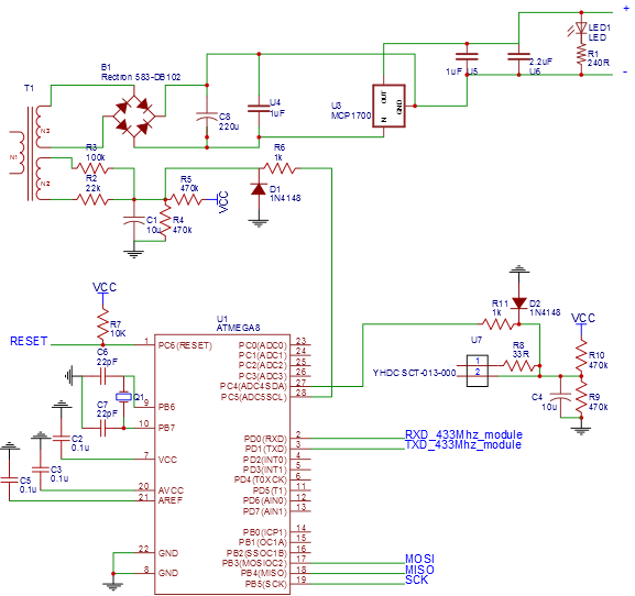
As mentioned in the discretion, I used a transformer with two secondary coils, so I could use one for the power supply and the other to measure the voltage. As the power source is used as the reverence for the ADC converter (Aref), it had to be very stable and precise.
The emonV3 has a build in MCP1702 linear voltage regulator with 0.5% tolerance. Unfortunately I could not get my hands on one of these, so I had to use an equally adequate LP2950 (50 Eur. Ct) with 5 V output voltage. After the usual capacitors to sooth the voltage I fed the µC with 4.99 V. According to the datasheet of the LP2950 the voltage is stable up to a couple 100 mA drawn.
Voltage measurement
The circuit for the voltage measurement is basically the same as for the emontx, except for the voltage divider right at the transformer exit (see This page for a very good explanation). The emontx uses a 100 and 10K resistor and a 9 V transformer, I use a 6 V one. So with these resistors and my smaller transformer I would end up with about 0.77 V coming from the transformer as a oscillating voltage on top of 2.5 V from the voltage divider. In sum only 3.27 V of the 5 V my ADC could measure.
So I would waste about 1.7 volts and with that resolution. So I exchanged the 10K resistor with a 22K one and end up with:
Add these 1.52 V to the 2.5 V from the voltage divider and you end up at 4.02 V, a much better voltage range for the ADC to work with.
µC power supply and reference voltage
I learned it the hard way how important decoupling capacitors are...
My ADC measurements were always a bit unstable until I read more about the ADC on a micro controller (RTFM!) and fixed this issue with some capacitors near to the IC.
Thats what I did to get stable ADC measurements
Create an account to leave a comment. Already have an account? Log In.
Thats cool, I'm ready whenever you are, let me know if you have any questions.
Cool project, would you also be interested in pushing your energy data to my project, analog.io? https://hackaday.io/project/4648-analogio-a-full-stack-iot-platform
Hey sorry for the long delay. I read that your project did not make it to the finals, sorry for that ! Are you still interested in my data / me dumping the data to analog.io ?
Become a member to follow this project and never miss any updates
Hey thats my first comment on hackaday ever ! Thanks ;)
I would like to complete this blog first and then check out your project in more detail. It looks interesting though !