-
1Step 1
Step 1: PCB´s
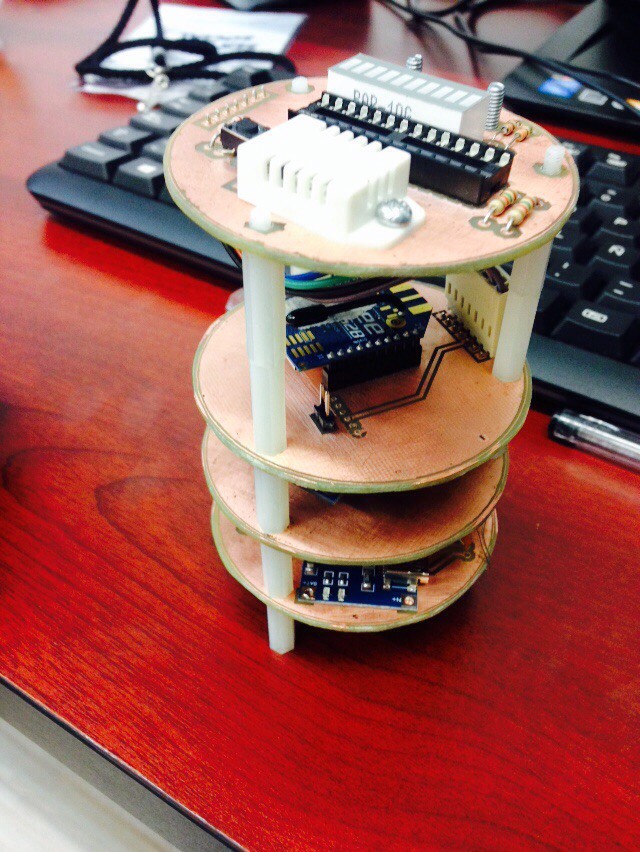
This Pico-Satellite have 4 subsystems:
- Electrical Power Subsystem (EPS)
- Command and data-handling Subsystem (C&DH or Fly Computer)
- Telemetry and Command Subsytem (T&C)
- Payload ( PL-01 and PL-02)
Each subsystem have their own PCB board, so we have two options:
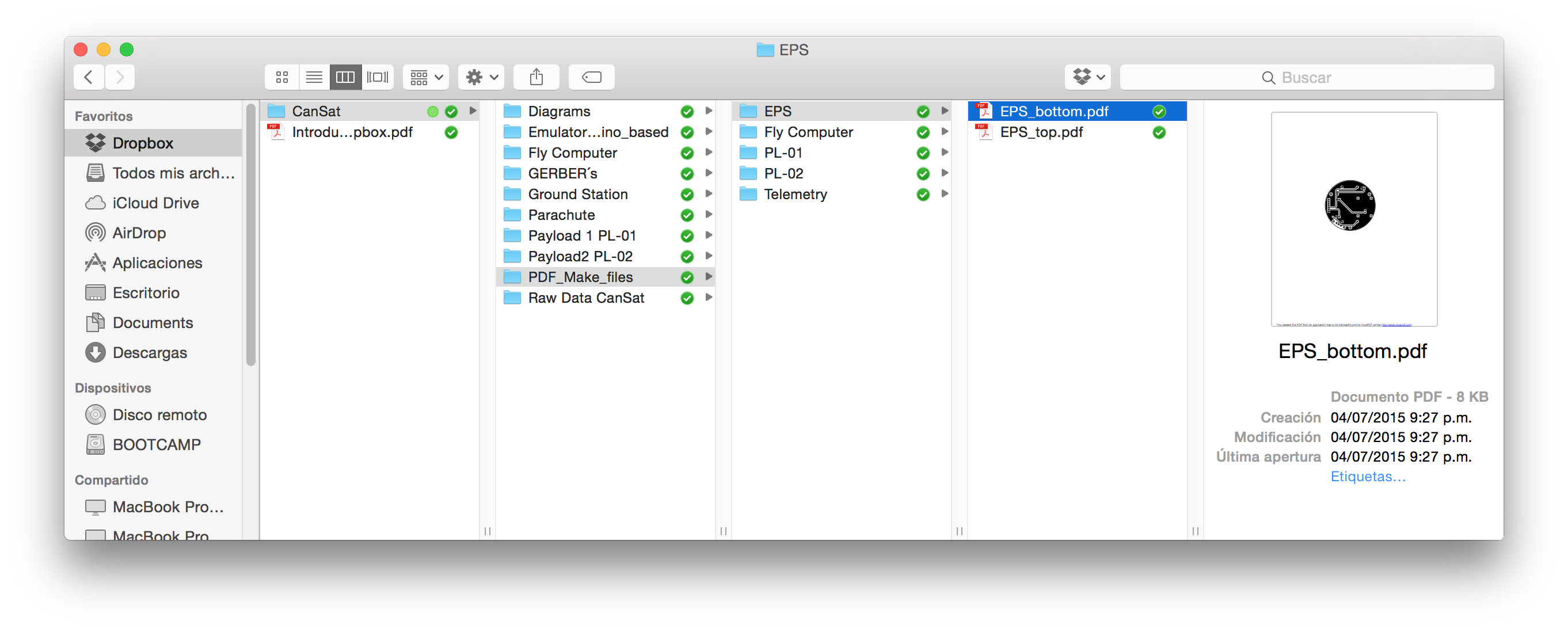
- Manufacture our own PCB´s using "PDF makes files"
- Pay a professional for do the PCB using the Gerber Files.
![CanSat using "PDF make Files"]()
![EPS using gerber files]()
The PDF makes files: Here
![]()
The gerber files: Here
![]()
-
2Step 2
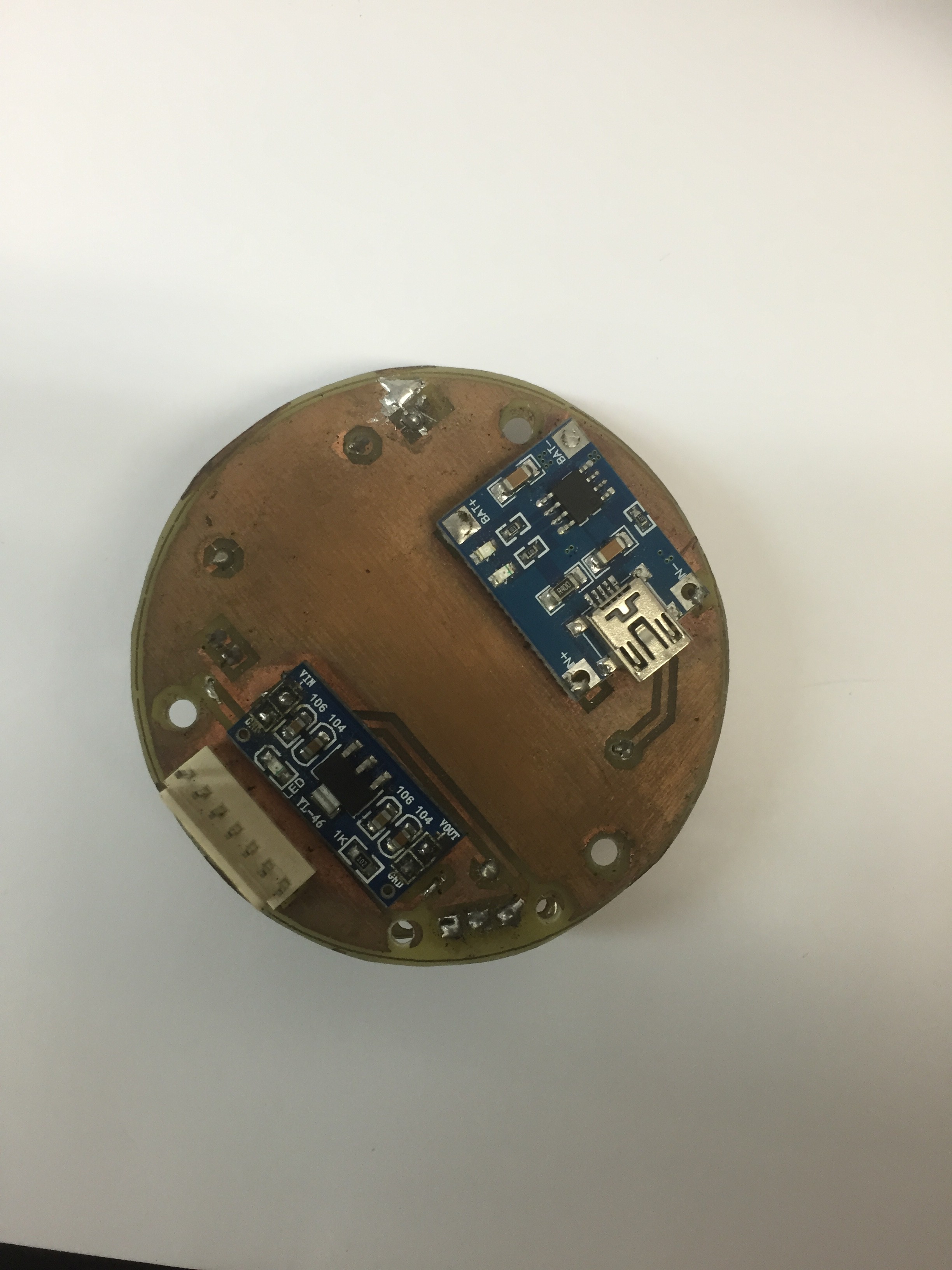
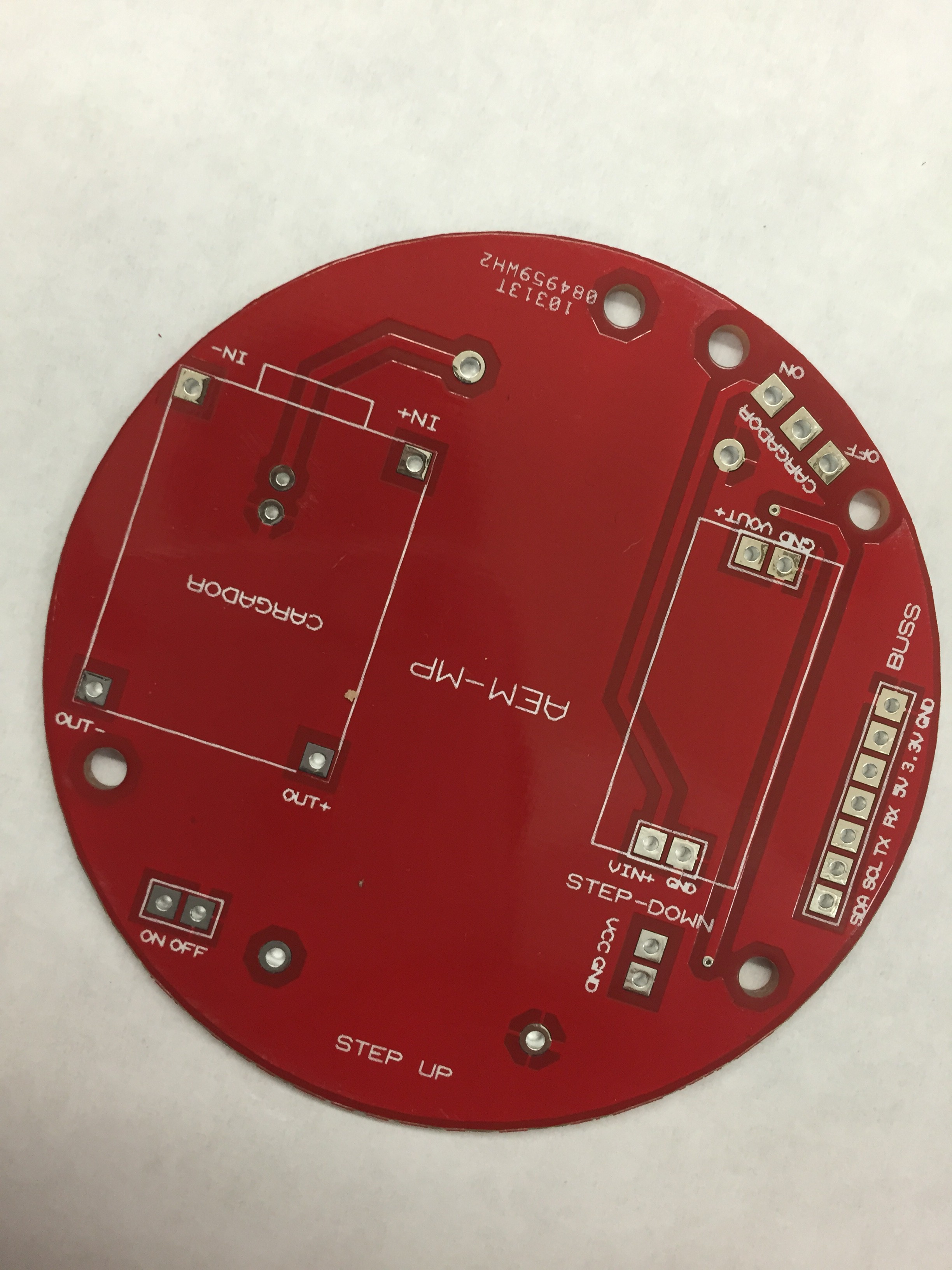
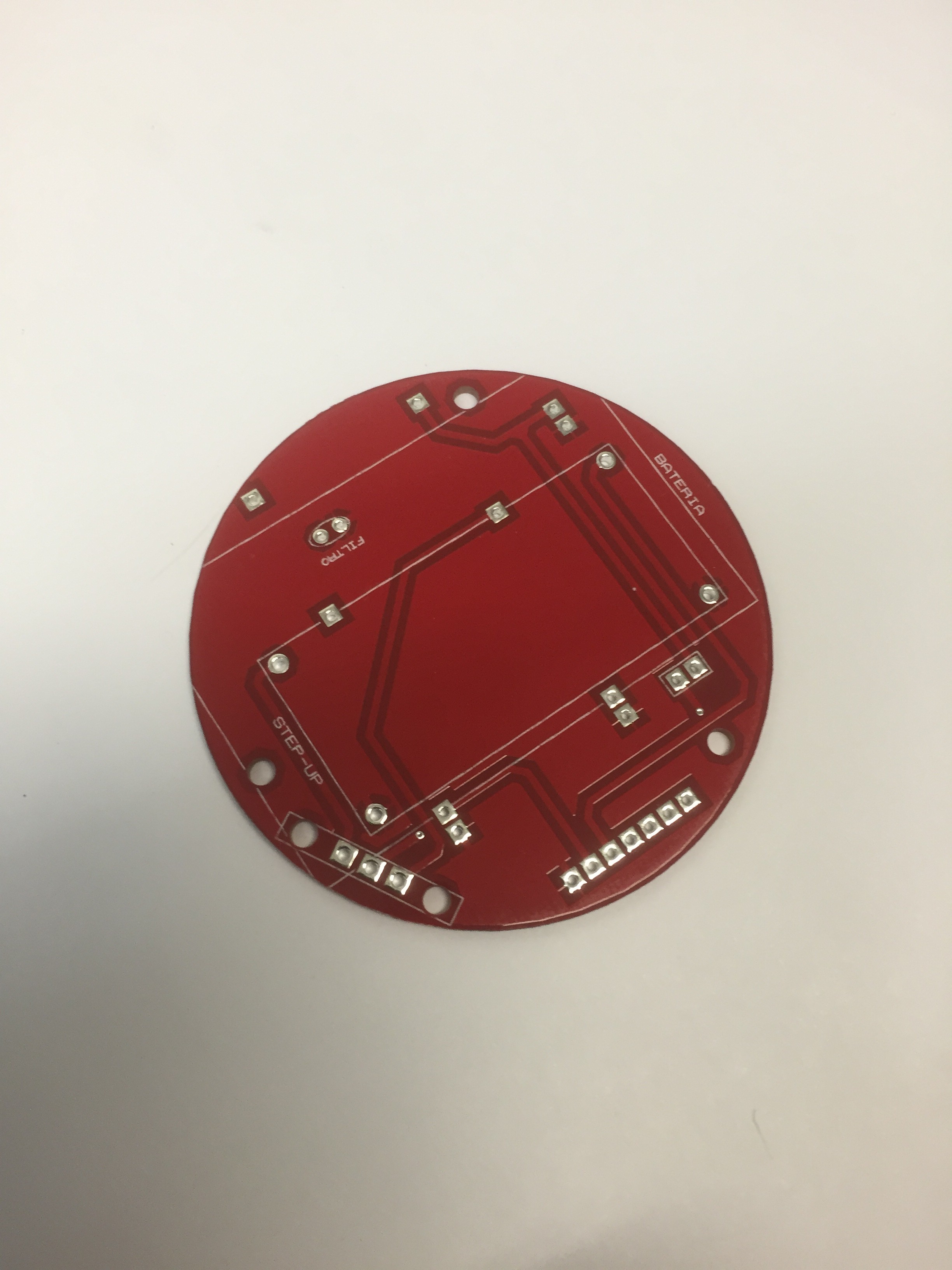
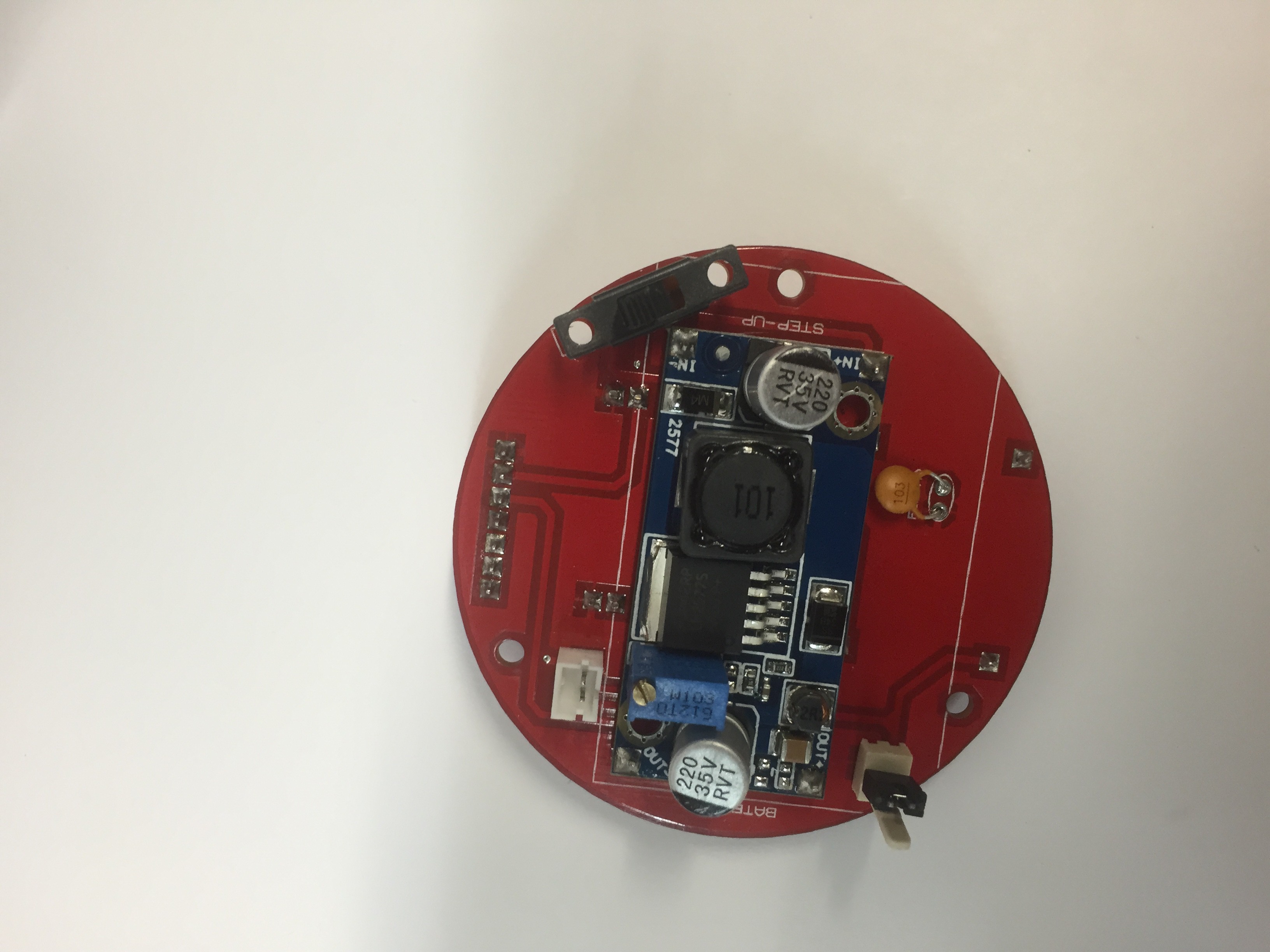
Step 2: EPS
Materials (click for image):
- PCB EPS (1).
- JST battery receptacle (1).
- Molex connector 7 pin, male(1). Really important... 7 PIN
- Molex connector 2 pin, male (1).
- Switch one pole two ways(2).
- Jumper ( for use only one switch).
- Ceramic Capacitor 103 (1)
- Step Up LM2577 Module (1)
- Lipo Battery 1200mAh 3.7v 1C JST connector (1)
- TP4056 Battery charger
- AMS1117-3-3 DC DC Step Down
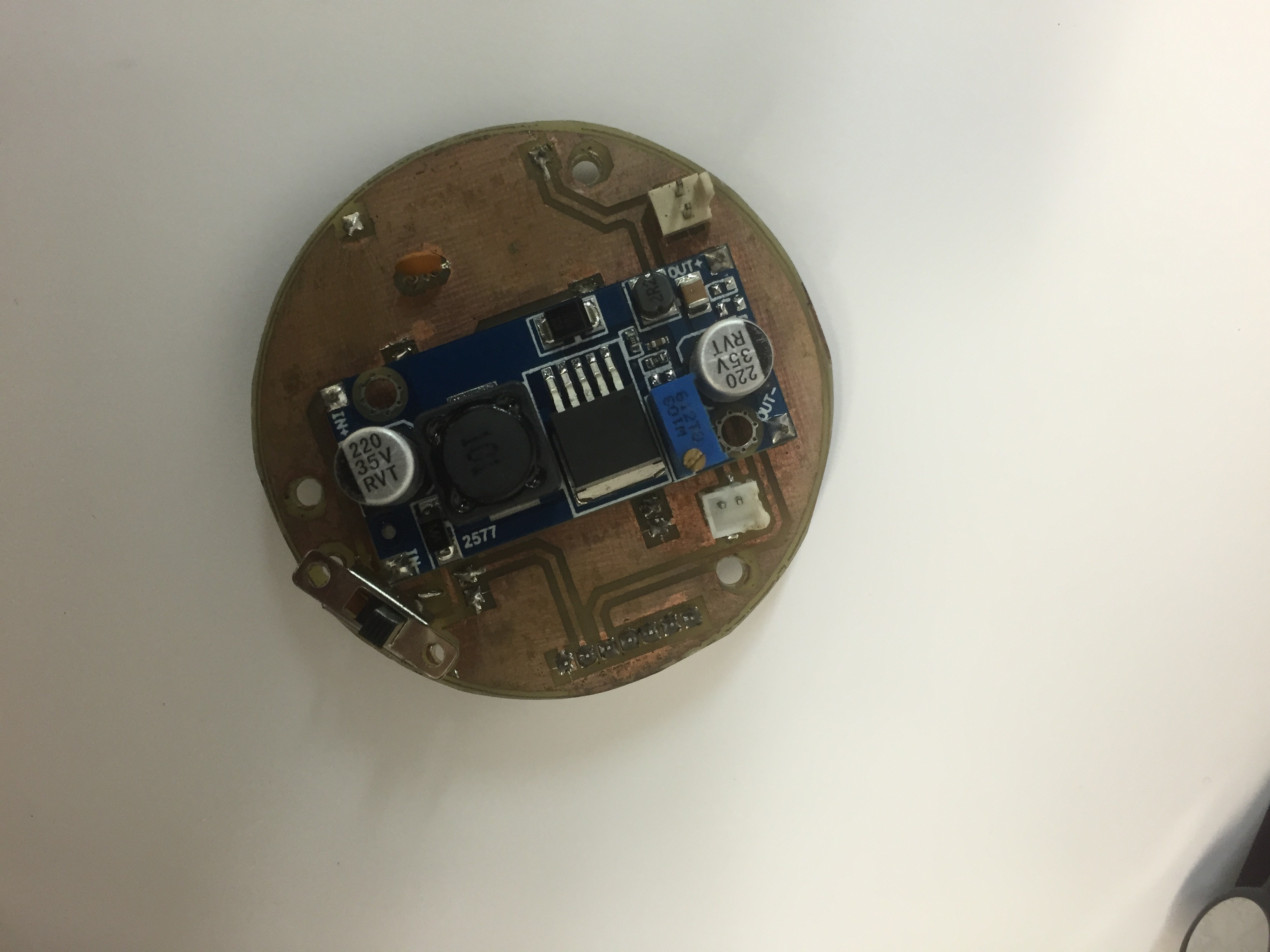
This is the view of the EPS welded.
The schematics are available: here
1.- PCB home made
![]()
![]()
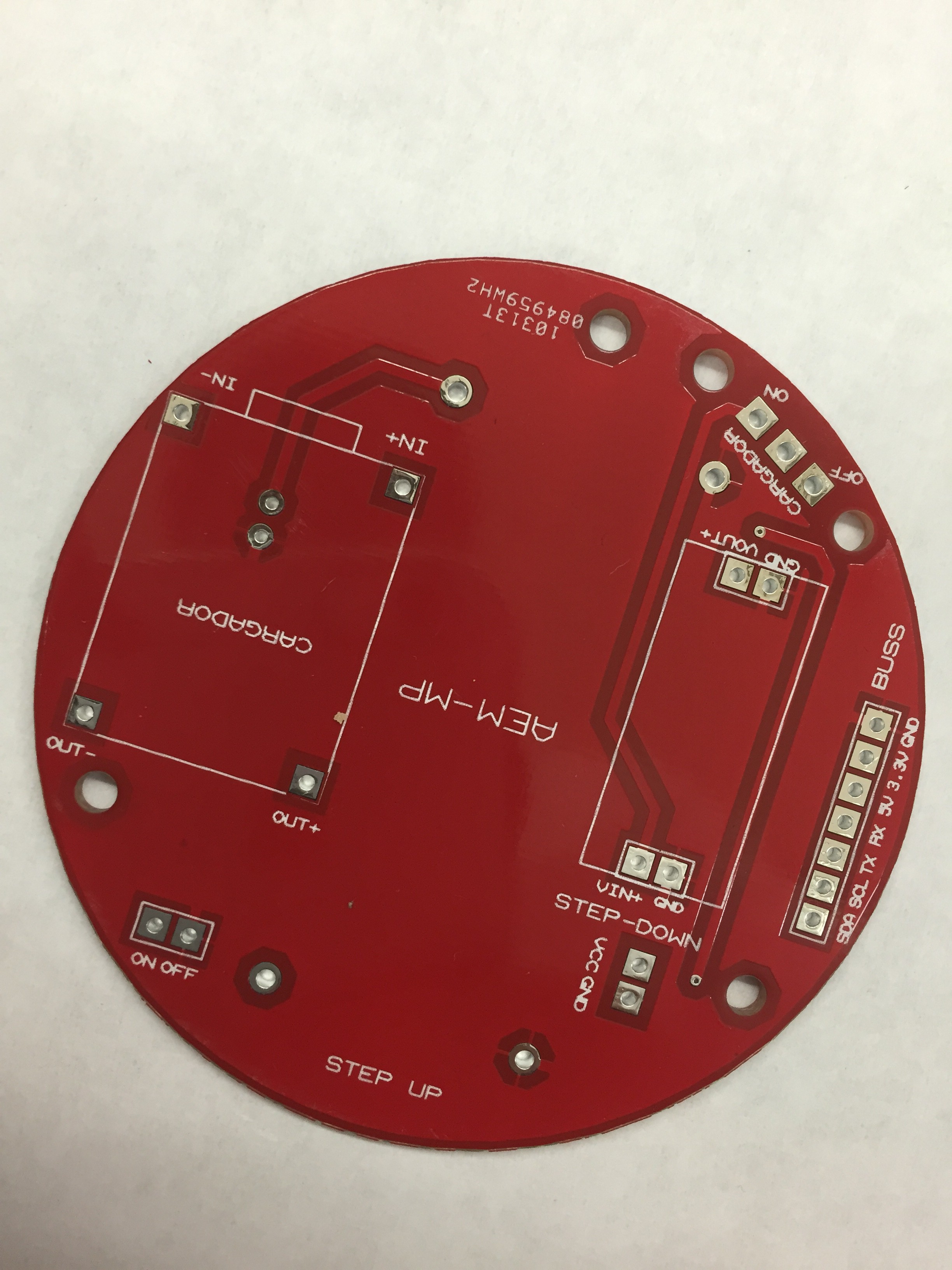
2.- PCB "pro"
Top View
![]()
![]()
Bottom
![]()
![]()
Its really important the orientation of each component, even the molex conector (BUSS). The conector of the baterry is JST.
-
3Step 3
Step 3: C&DH (Fly Computer)
The C&DH subsystem have 2 variants:
1.- The Arduino pro Mini 3.3 8 Mhz Atmel328 based fly computer.
2.- The Intel Edison based fly computer.
The first one is finished and proved, work well but have a really low power of processing so, we cant use all the functions of the on board sensors,
The second one provide us a really powerful processor and access to all on board sensors functions, but i'm still working in the development on the required libraries. Also requires an advanced welding skills, because the components are SMT.
So here is the Arduino based fly computer. (Code & Schematics)
Materials(click for image):
- Arduino Pro mini 3.3v 8Mhz atmega328 (1)
- IMU GY-80(1)
- 10k 1/4watt resistor (1).
- Push button (1)
- 2.54mm angle 90 header (6)
- 2.54mm header(2)
- Molex connector 7 pin, male(1). Really important... 7 PIN
- FTDI 3.3v Cable
The schematics are available: here
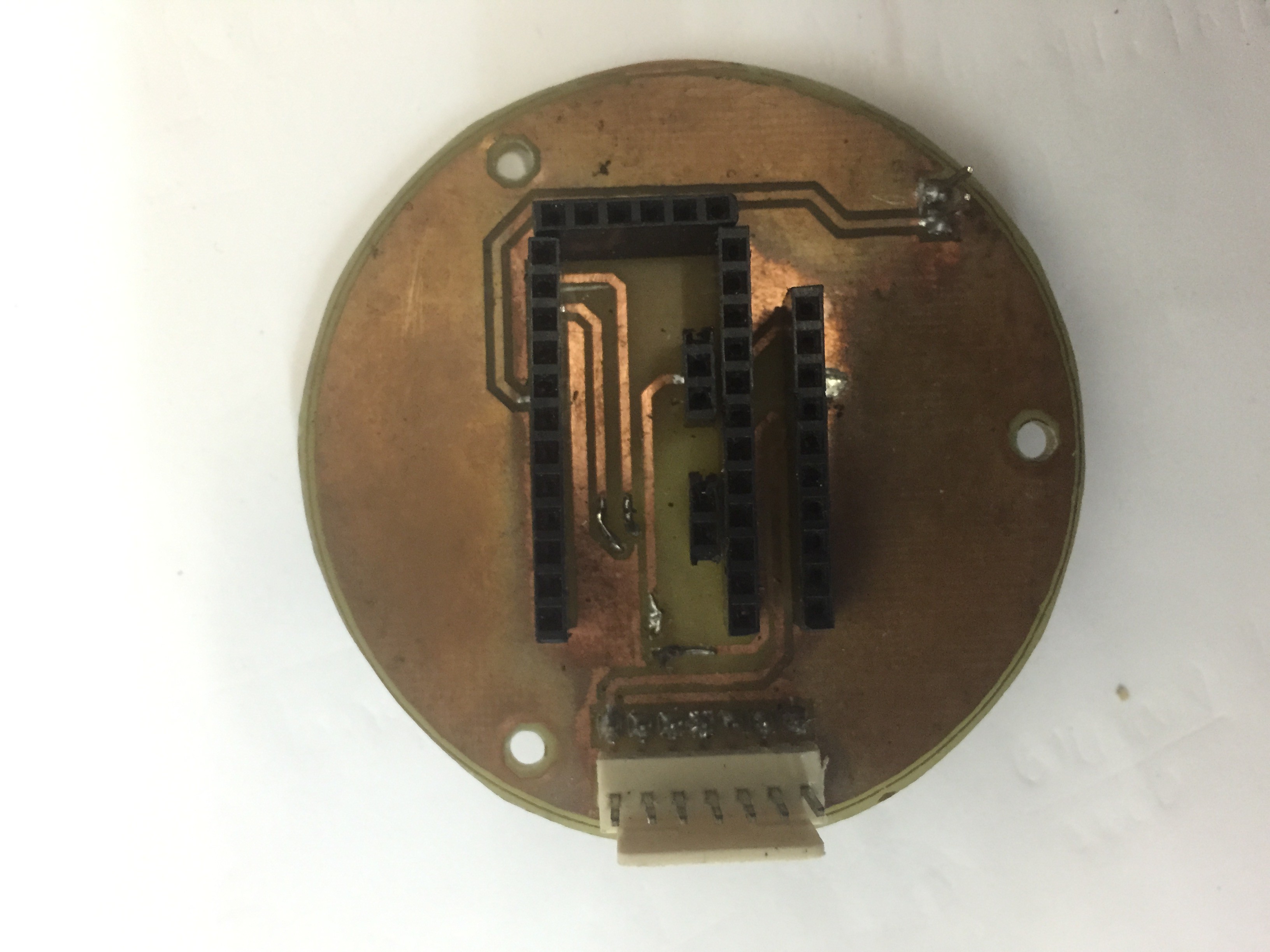
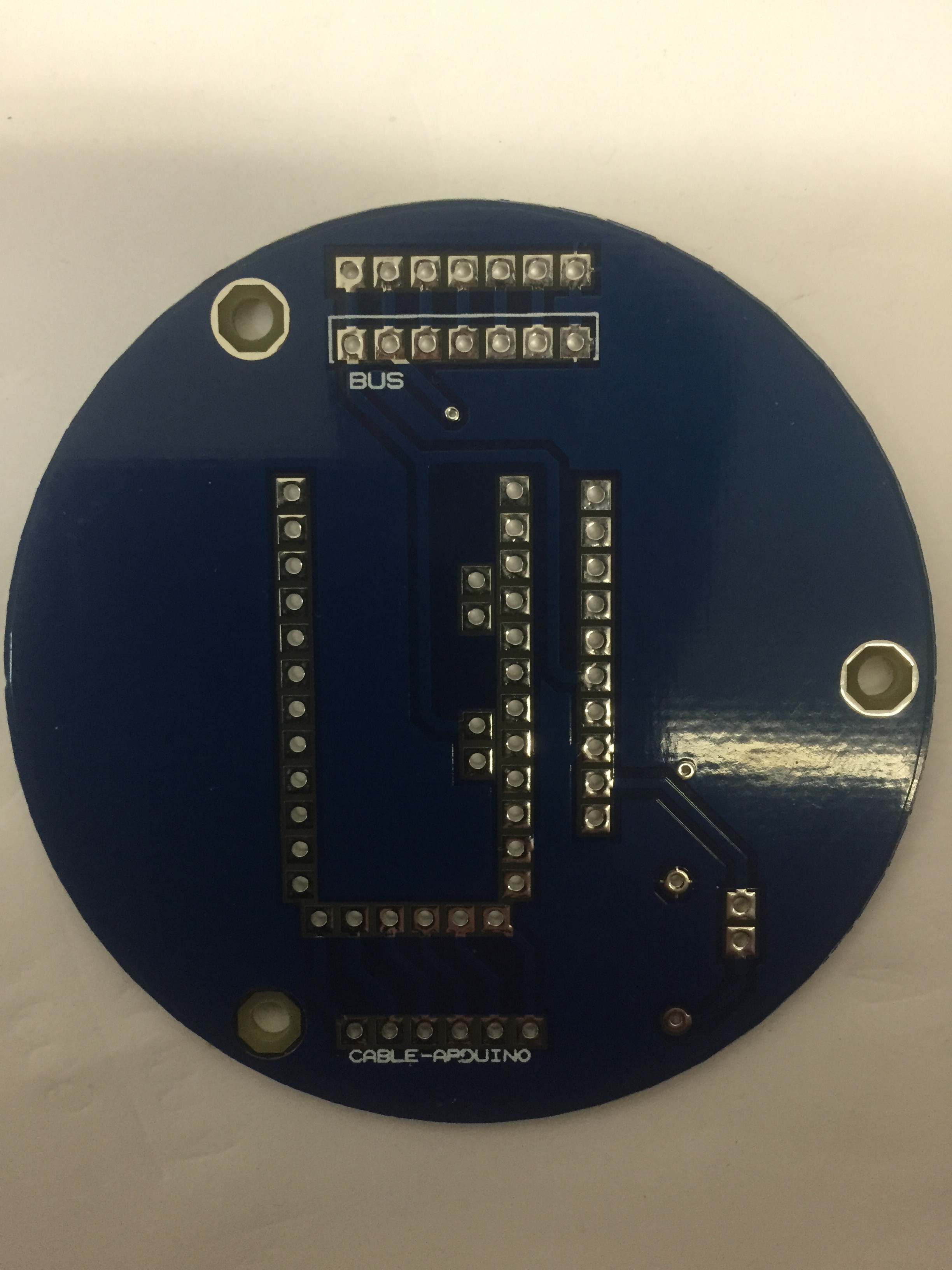
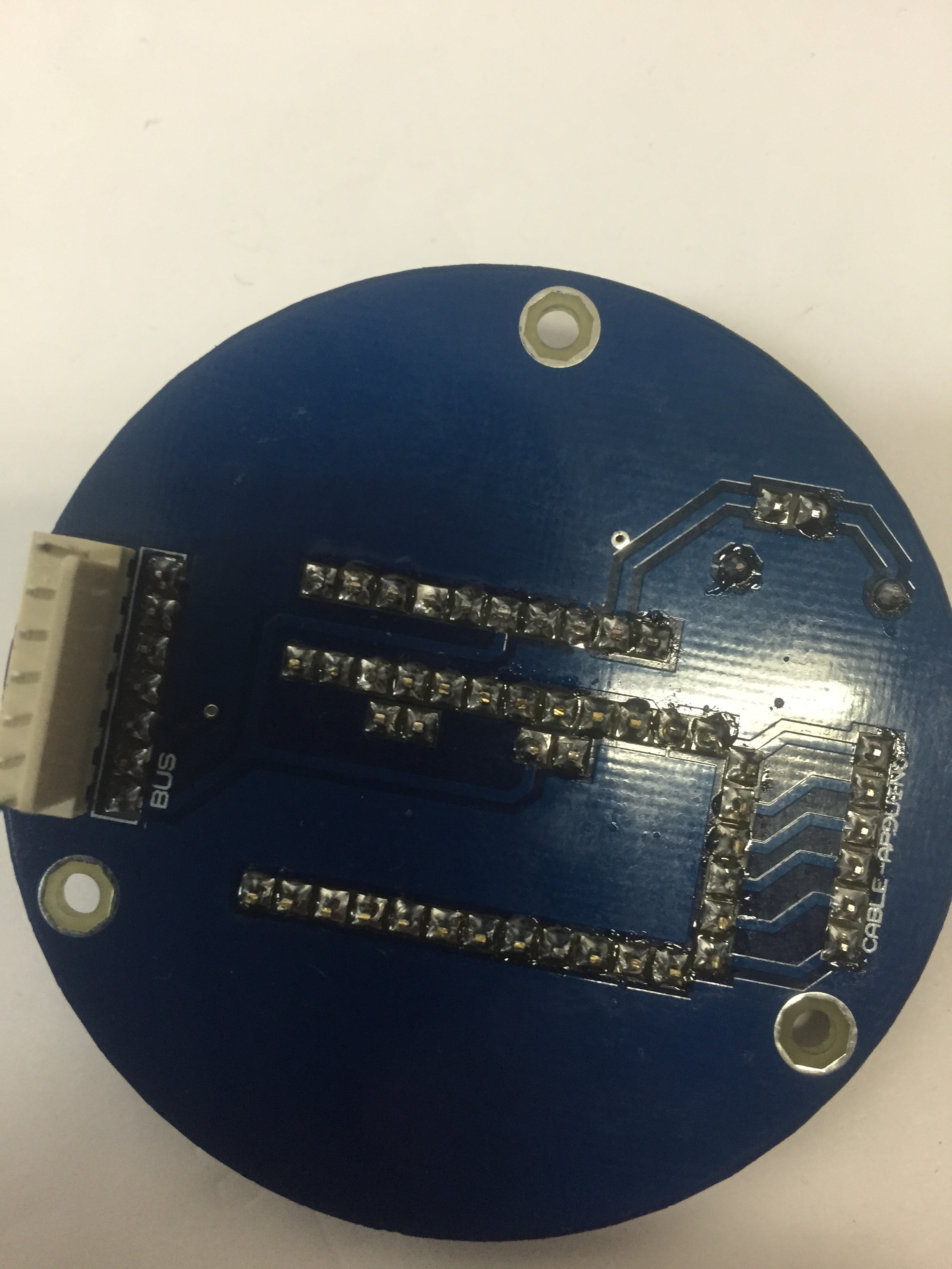
- Home Made PCB
Top
![]()
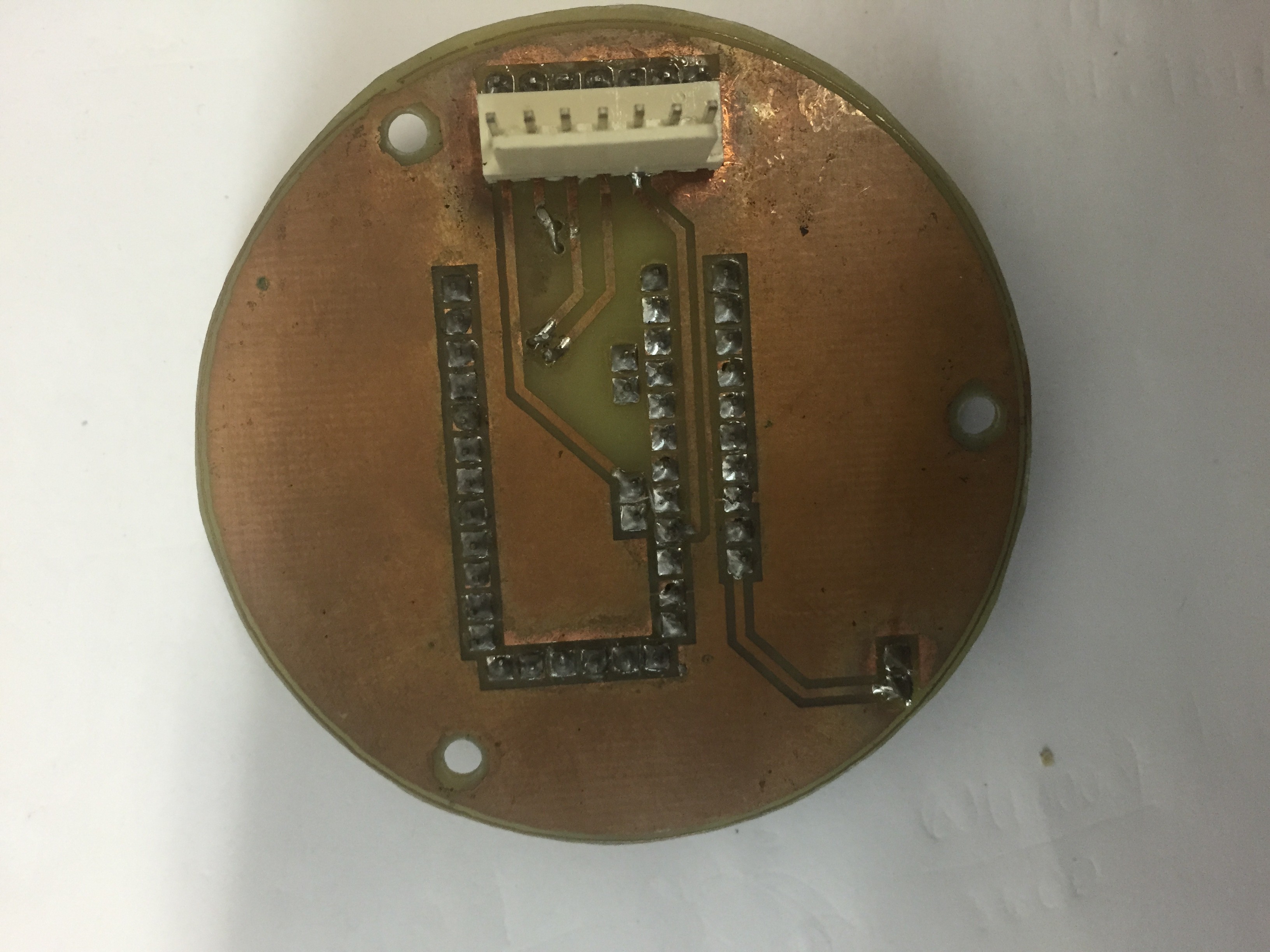
Bottom
![]()
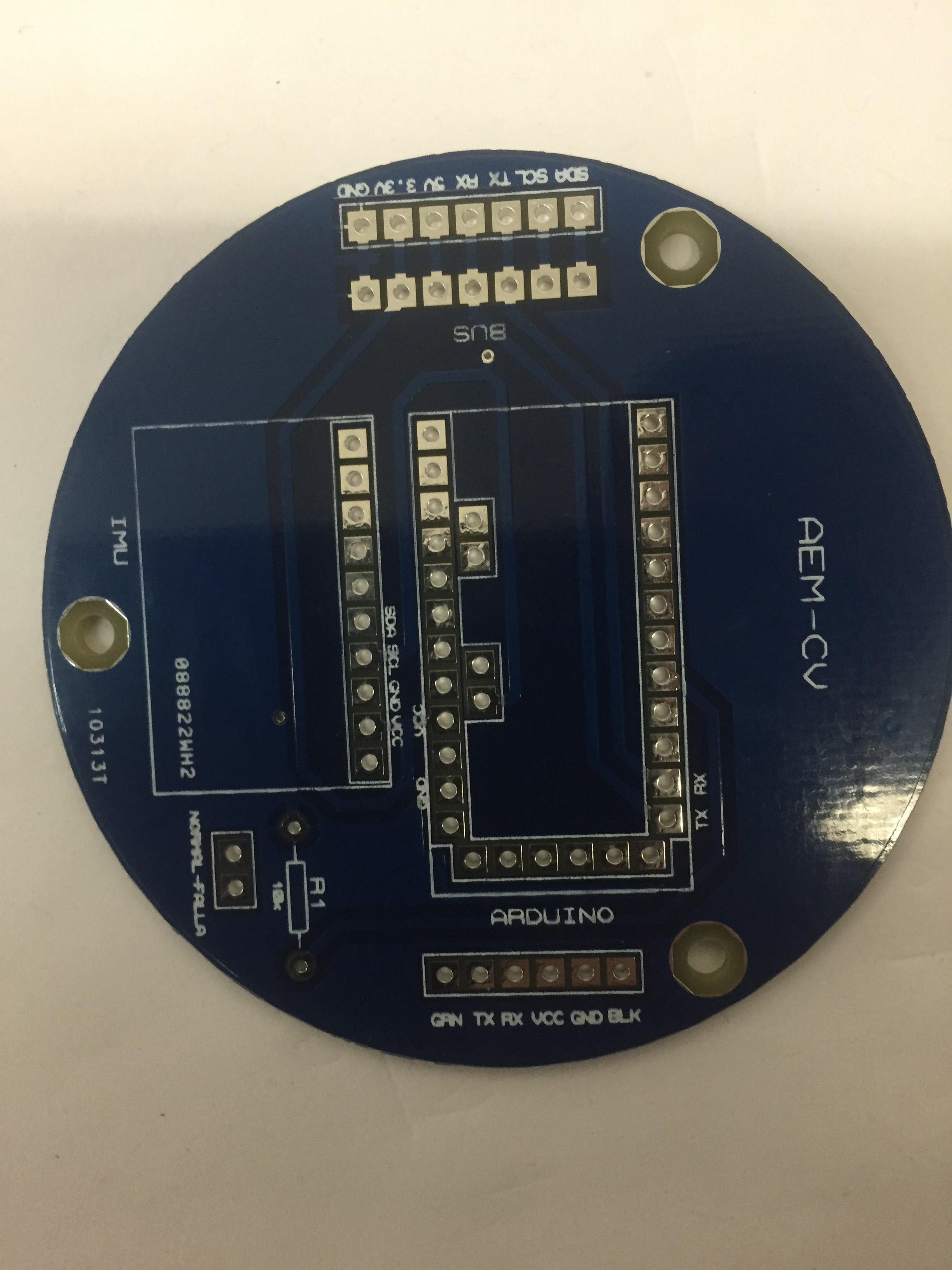
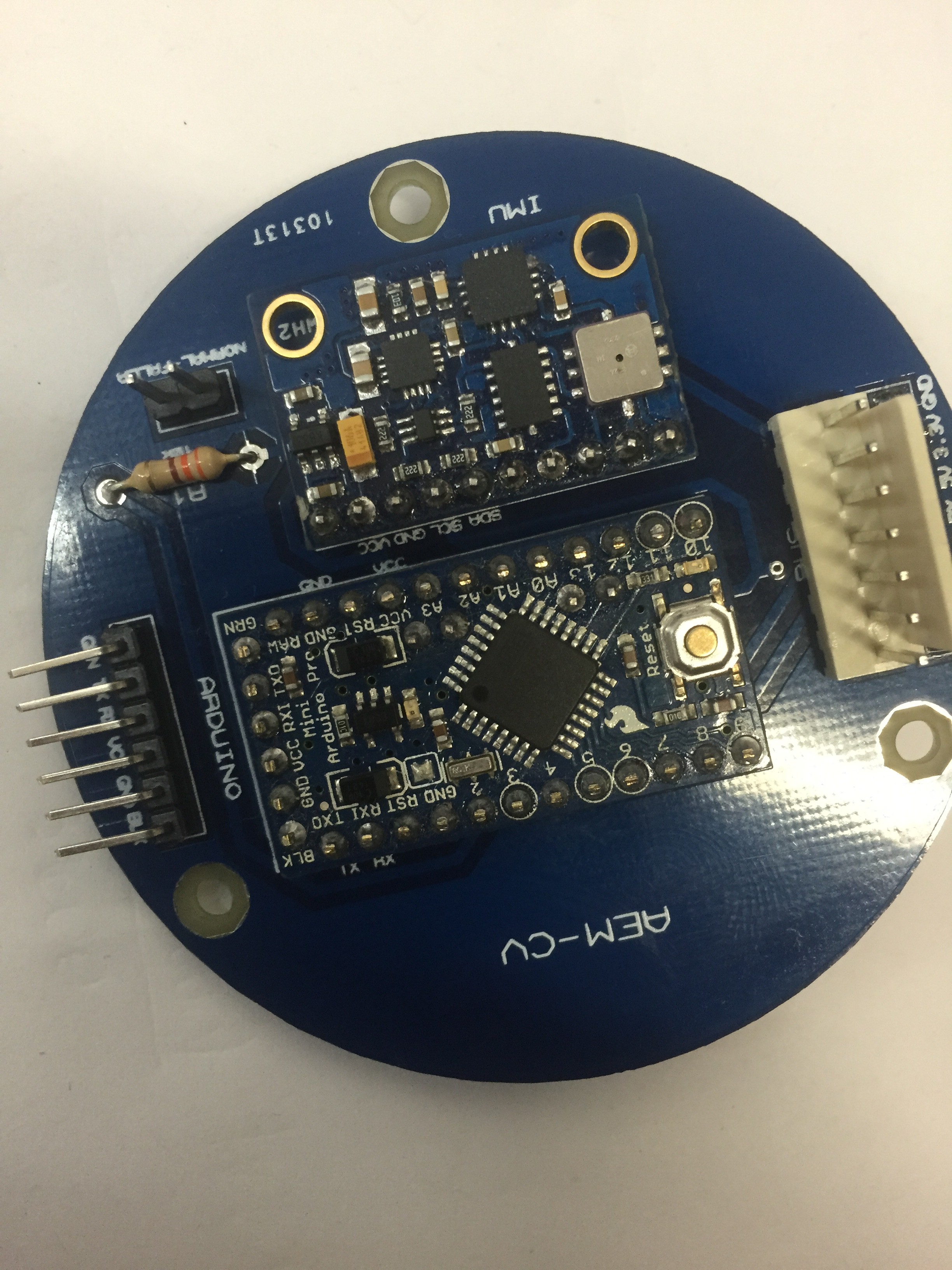
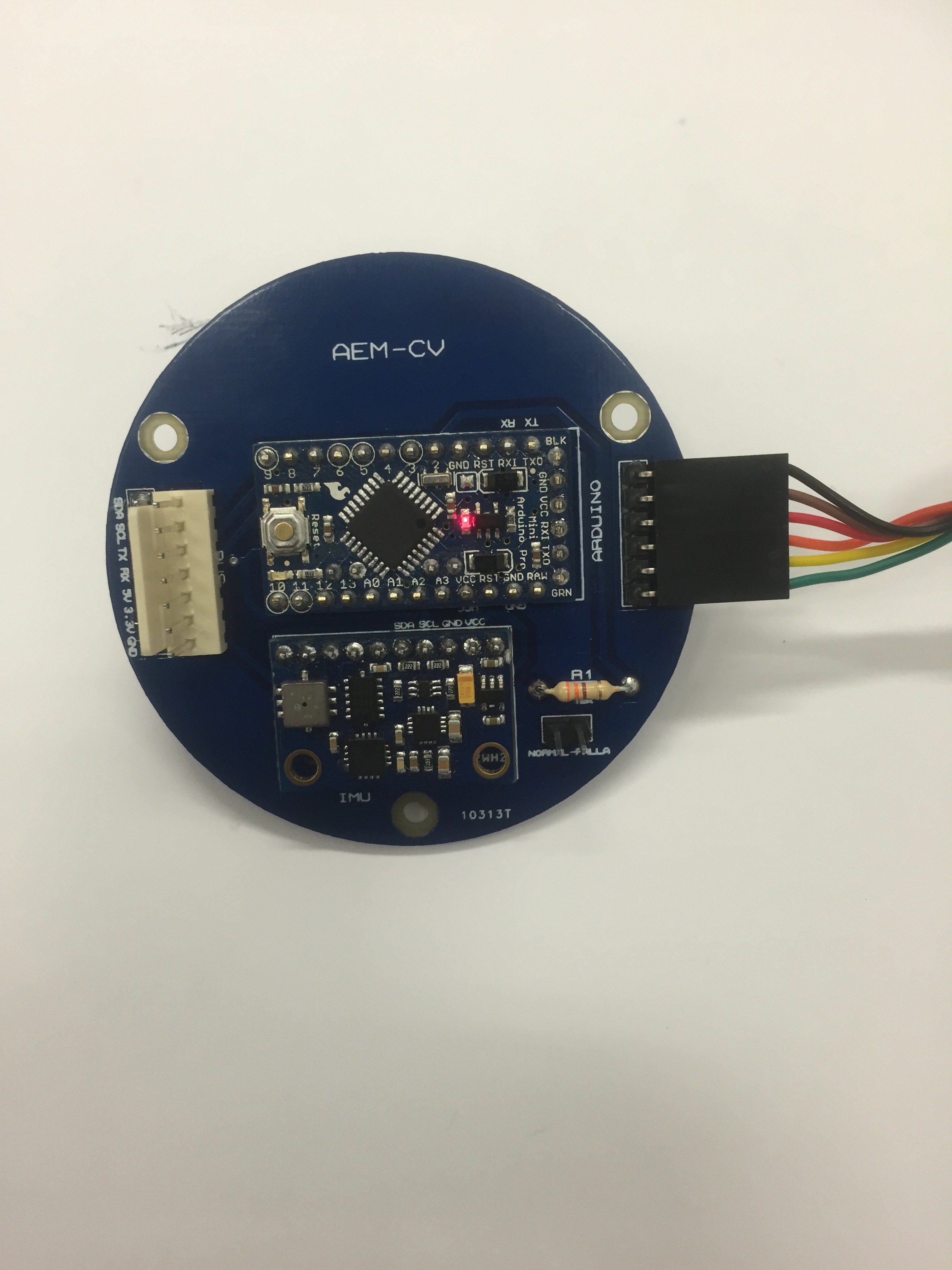
- PCB "Pro"
Top View
![]()
![]()
![]()
Bottom View
![]()
![]()
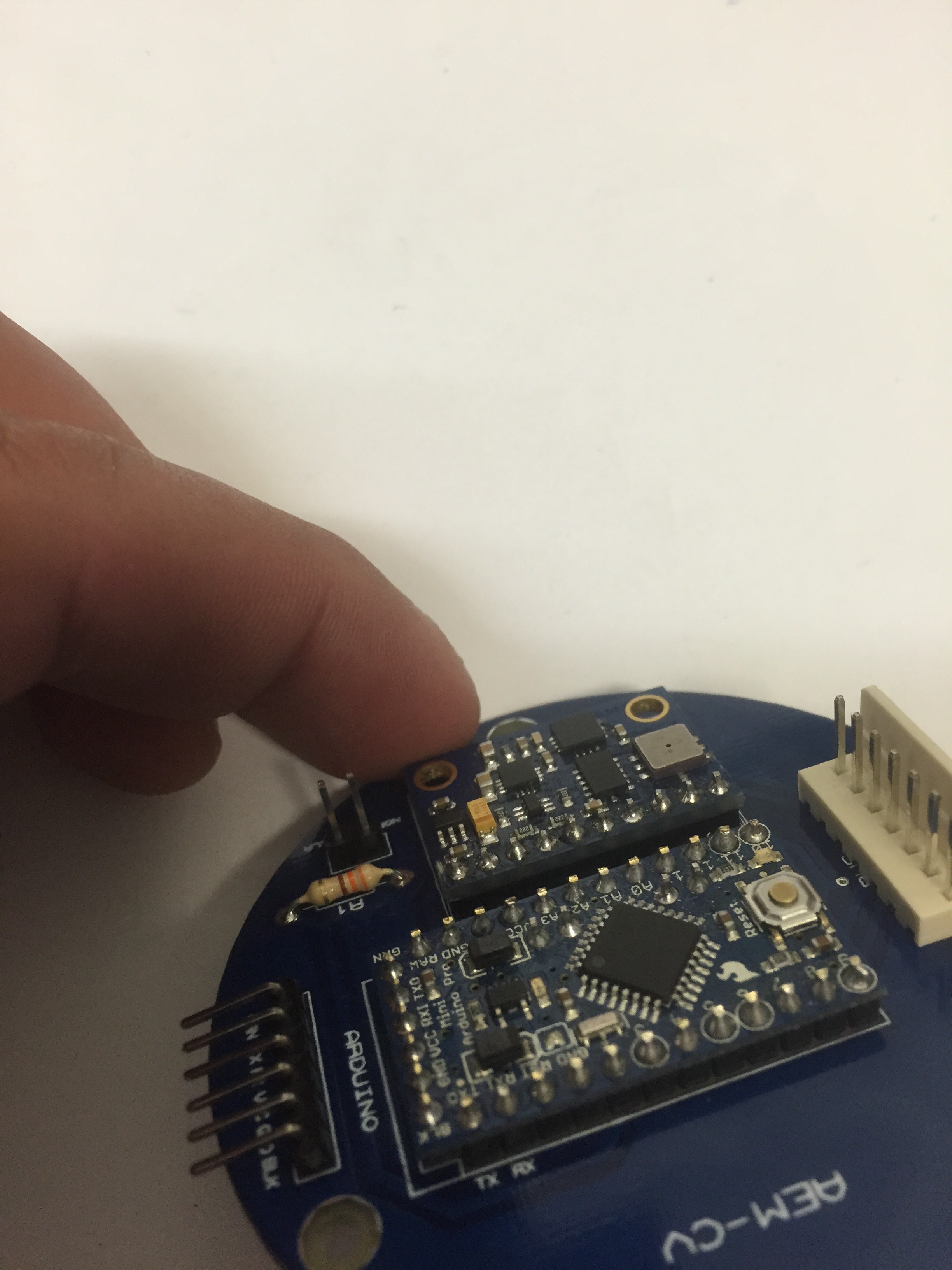
For test the C&DH subsystem, you can Scan I2C directions with this program using the FTDI cable connected as shown in this picture
![]()
And the serial monitor of the Arduino IDE will show this:
![]()
-
4Step 4
Step 4.- Telemetry and Command Subsytem (T&C)
-
5Step 5
Step 5.- Payload (PL-01)
-
6Step 6
Step 6.- Payload (PL-02)
-
7Step 7
Step 7.- Buss (Molex)
-
8Step 8
Step 8.- Integration And Testing.
-
9Step 9
Step 9.- Exchanging Payloads.
CanSat - Exchangeable Payloads Arduino And Edison
You can Exchange the payload and the fly computer,


Discussions
Become a Hackaday.io Member
Create an account to leave a comment. Already have an account? Log In.