 Austin Marandos
-
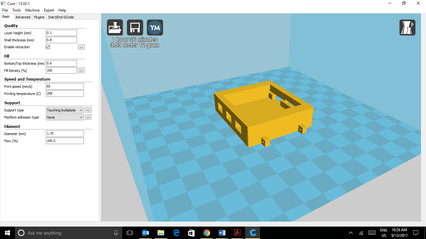
13D printing the case
Start by downloading the 3D print files in the 'files' section.

Depending on your printer the settings will vary however i would recommend
-100% Fill density
-Supporting structures are a must
- PLA or ABS plastic is fine.
The print should take around an hour and a half (depending on the speed of your printer). The geometric shape is relatively simple so you can print at a normal speed.
If you do not own a 3D printer, 3D hubs (https://www.3dhubs.com/) is a great site, it allows you to 3D print any file from community based printers around your area.
-
2Purchasing electronics
You will need the following:
Version 1: (without RTC)
- Freetronics OLED 128x128 screen (purchased from: https://www.freetronics.com.au/products/128x128-pixel-oled-module)
-Adafruit pro trinket 5V (https://www.adafruit.com/product/2000)
-Adafruit 3.7v 500Mah LiPo (https://www.adafruit.com/product/1578)
- Adafruit 5V boost circuit (https://www.adafruit.com/product/1903)
Version 2 (with RTC)
- Sparkfun DS1307 (for 5volts) (https://www.sparkfun.com/products/12708)
- or alternatively for a 3.3v system you can use the DS3231 RTC (https://www.alibaba.com/product-detail/DS3231-Real-Time-Clock-Module-for_60455474982.html)
-
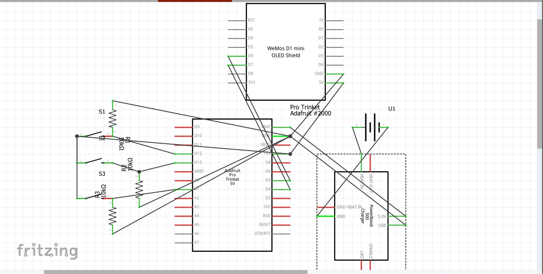
3Circuit Construction
Create the circuit as per the diagram:
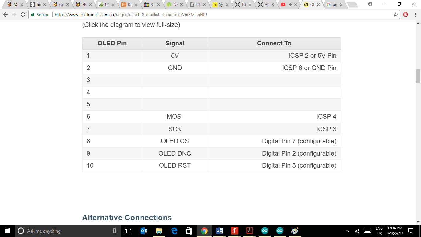
Please note: The OLED screen in the circuit diagram above is incorrect, unfortunately there was no Fritzing file for the freetronics OLED. To attach the OLED screen please follow the very detailed guide on the freetronics website: (https://www.freetronics.com.au/pages/oled128-quickstart-guide#.WbiXMsgjHIU).
Pinout for OLED screen:
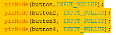
Buttons:
For the buttons i originally used resistors and passed 5 volts through the button with a 10k ohm resistor to prevent any damage. This is a complete waste of space. You can easily use the buttons without resistors by utilising the 'INPUT_PULLUP' state in the Void setup() of the code.
You will need to swap your buttonstates if you do it this way:
ie:
instead of if(buttonstate == HIGH) {}
change to if(buttonstate == LOW) {}
-
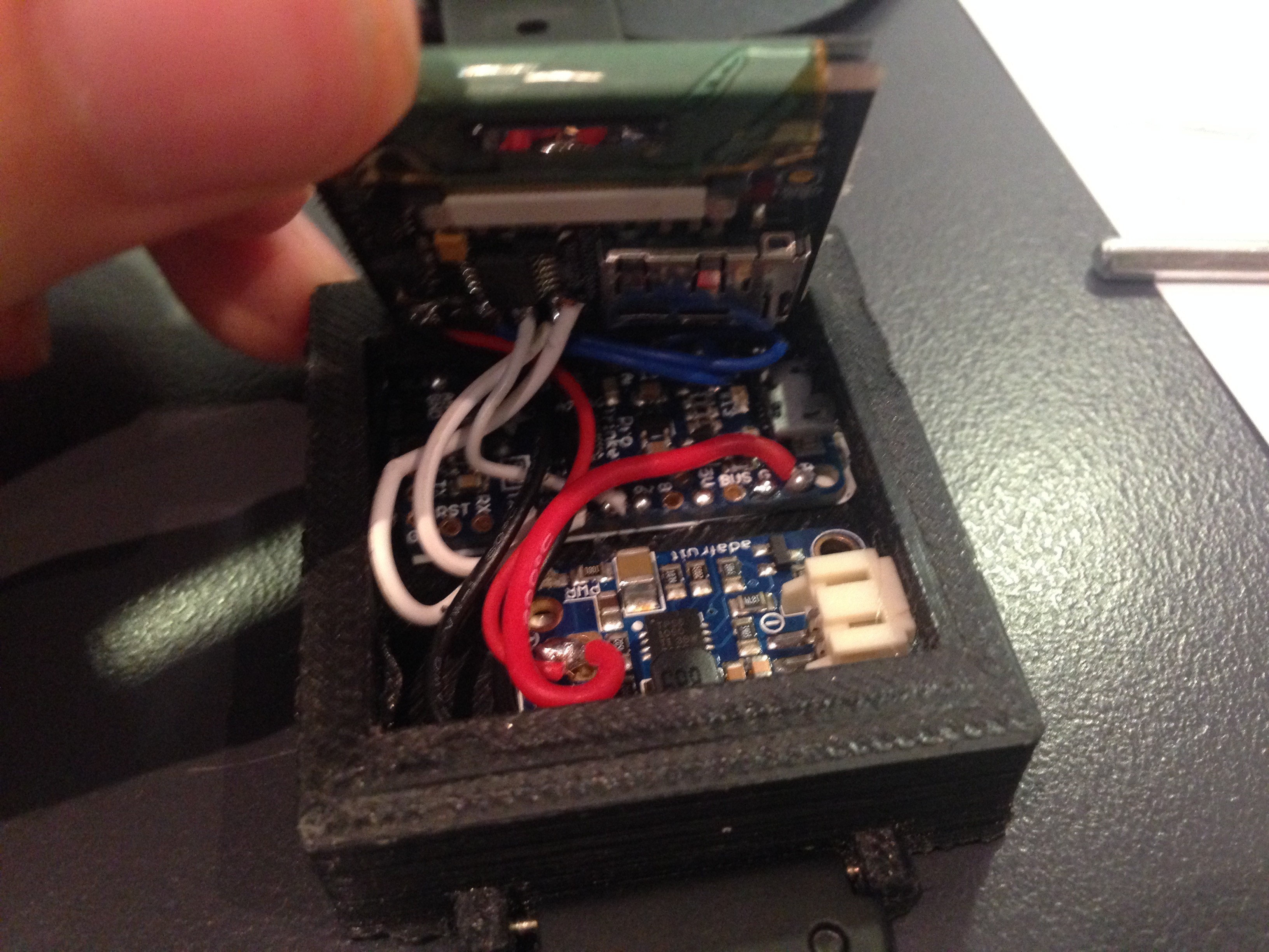
4Installing electronics
This is a relatively difficult step. Fitting all the electronics into a small space can be a challenge.
The 3D printed case should help with this process.
Instructions:
1) Attach watch band onto 3D printed watch case.
2) Place down the Pro trinket board with the 5V boost board on the bottom of the case. (you can put hot glue on the bottom of each board, however the friction alone should hold it in place).
2) Ensure that the USB slot of the pro trinket and the 5V boost board output connection is sticking out of the watch case.
3) If you didn't solder the electronics in the last step, now is your chance to make all necessary connections. (i would recommend soldering first as it can be difficult once the electronics are installed and you can end up burning the watch case).
4) Place buttons and resistors inside slots.
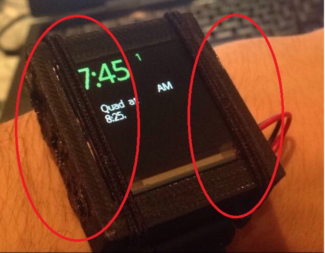
5) Place screen firmly down and ensure that all wires are enclosed.
6) use rubber bands or hair bands to keep the screen in place
Battery placement:
The battery can either be place below the watch (as seen in image) or it can be glued onto the watch band.
-
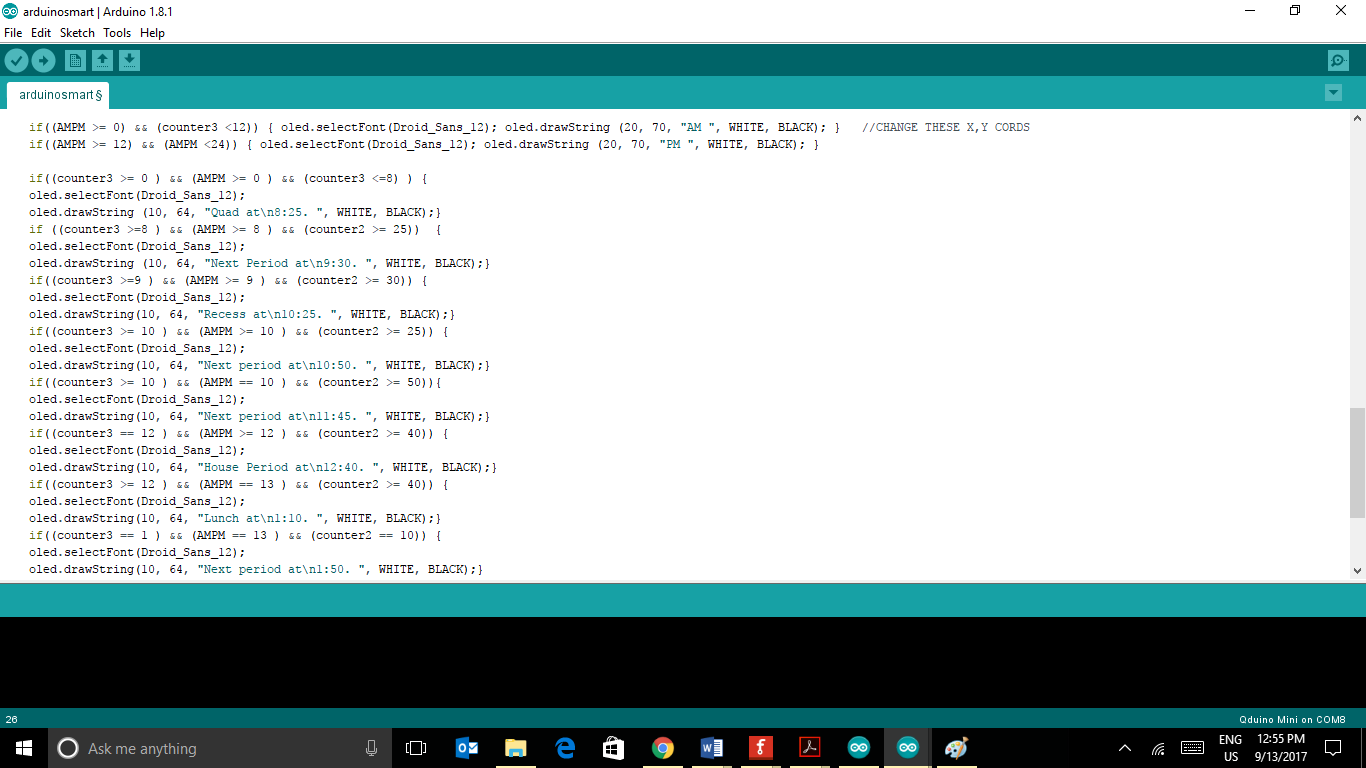
5Programming
Download the code from the 'files' section on the project page.
Once installed open on the Arduino IDE and upload!
Adjusting Time table reminder:
The time table can be easily changed within the code, by simply changing the text.
Arduino Smart Watch
A very basic yet expandable smart watch based upon Adafruit's 5v Pro Trinket board

Discussions
Become a Hackaday.io Member
Create an account to leave a comment. Already have an account? Log In.