-
New Resonators arrived
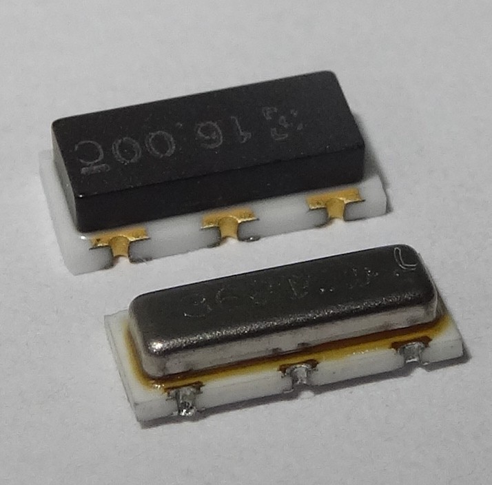
09/20/2015 at 13:38 • 1 commentThe 16MHz resonators I did ordered arrived. Thy do have the same footprint as the original 3,6864MHz resonators. In the picture you can see the new (top) and the old (bottom) resonator
With a hot air station it was easy to change the resonator. And the Atmega32L does run at 16MHz and supply voltage of only 2.8 Volts (this is according to the datasheet out of spec). 3.3V regulators are ordered, so I will l try them also.
-
It'S playing some music
09/14/2015 at 19:52 • 1 commentTone is created by a simple square wave. Next I will try to load a small wave file onto the ATmega. This should sound better than.
-
It's working
09/13/2015 at 15:43 • 0 commentsWith help of the code from the Trollmaster3000 I did managed it to work. More later or tomorrow....
The two cinch connectors on the left are one input of the radio and a one output of the Atmega connected together. The Atmega creates some tones. Also about this tones I will write something more soon.
-
Attaching wires to the board
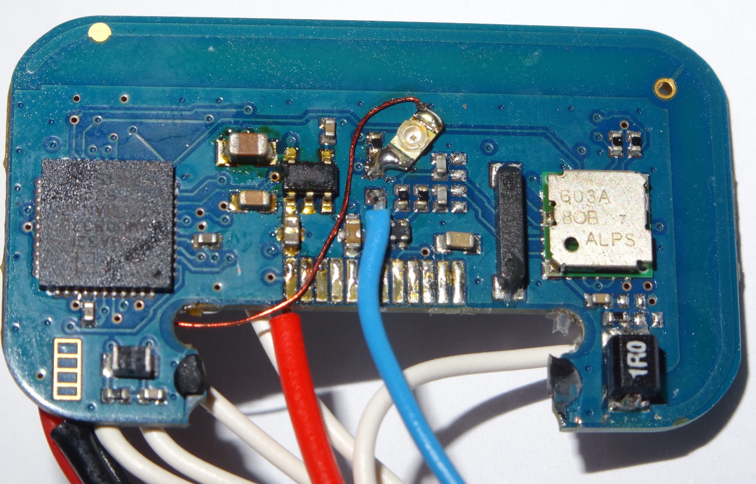
09/12/2015 at 19:04 • 0 commentsFor playing with the MMR-70 board i did add some wires. First I added A ISP_programming header to reprogram the ATmega32L and some power supply wires. On the the picture you can also see my second step: desoldering the led to get access to pin PD7 (the blue wire) and a new LED connected between the original Led resistor and PB0/PAD4. PD7 can be used by the output compare unit of Timer2 to generate simple square waves.
So far did not used the radio modul itself. Frist I will try to generate some tones, to transmitt them later
 Alex
Alex With a hot air station it was easy to change the resonator. And the Atmega32L does run at 16MHz and supply voltage of only 2.8 Volts (this is according to the datasheet out of spec). 3.3V regulators are ordered, so I will l try them also.


