Rocketburns
-
Back to drawing board
12/11/2015 at 01:13 • 0 commentsNot revealing much yet, but I found some more e-waste that will significantly improve this design. Off to the laser cutter!
-
Its Alive!
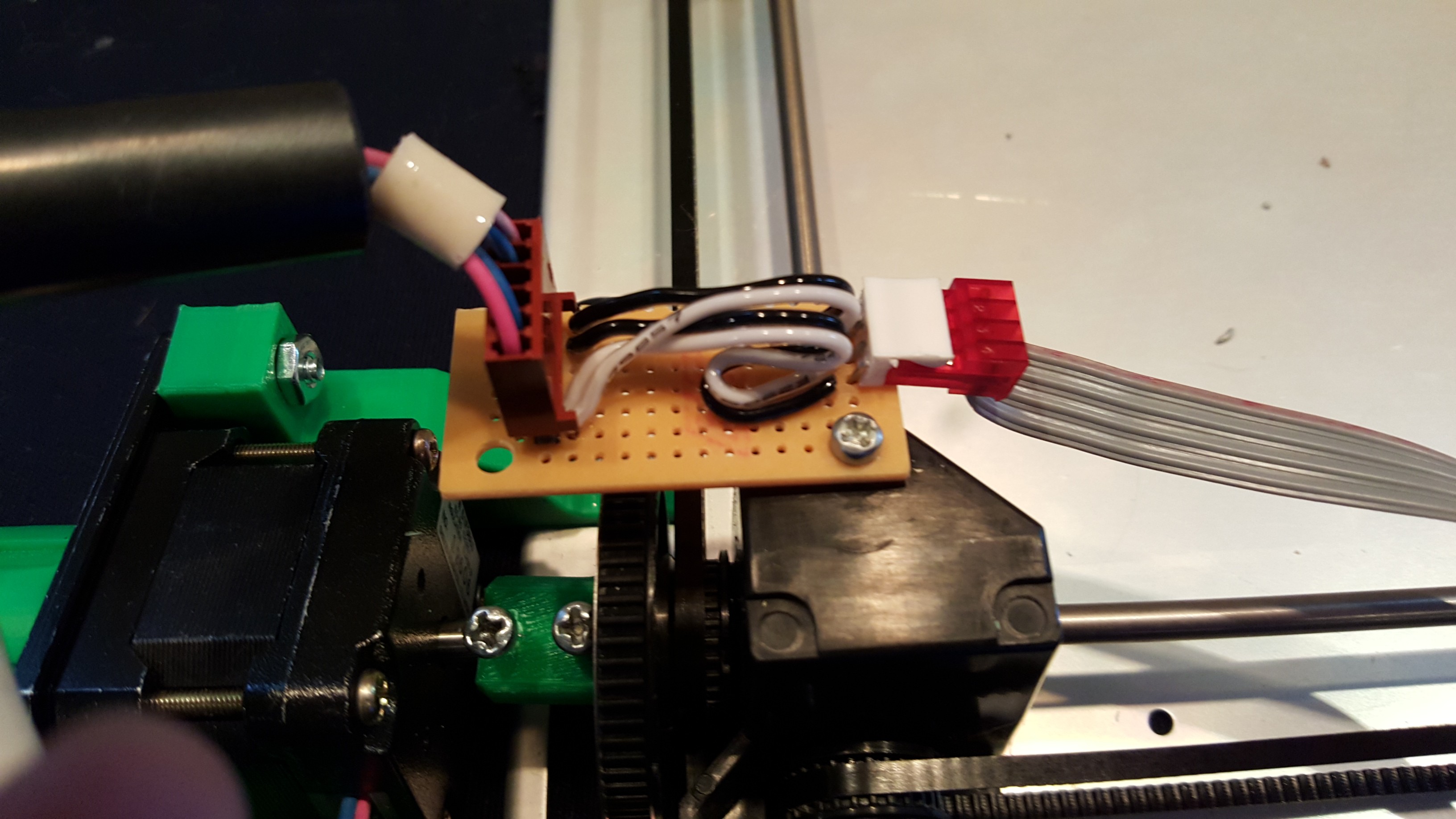
09/22/2015 at 23:21 • 0 commentsBig update, it actually can write now! A lot have things have happened in between updates, so I will attempt to fill in all the gaps now. First of all, I had to make some quick adapters for the stepper's connections:
![]()
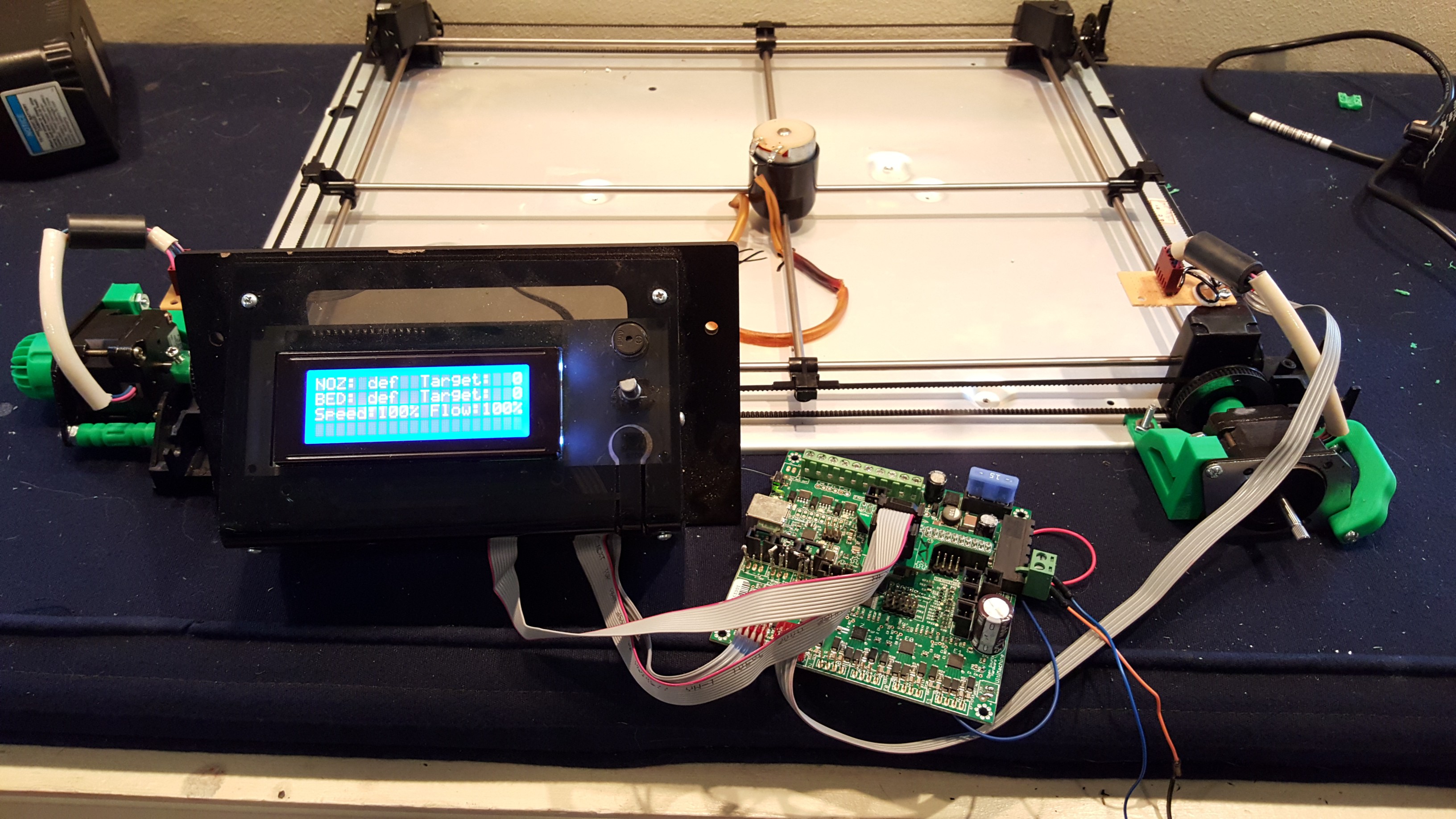
This ensures they will fit the controller board I am using. Also, I had to replace one of the shaft collars because it wore out, but that was minimal effort. Next, I wired up the control board:
![]()
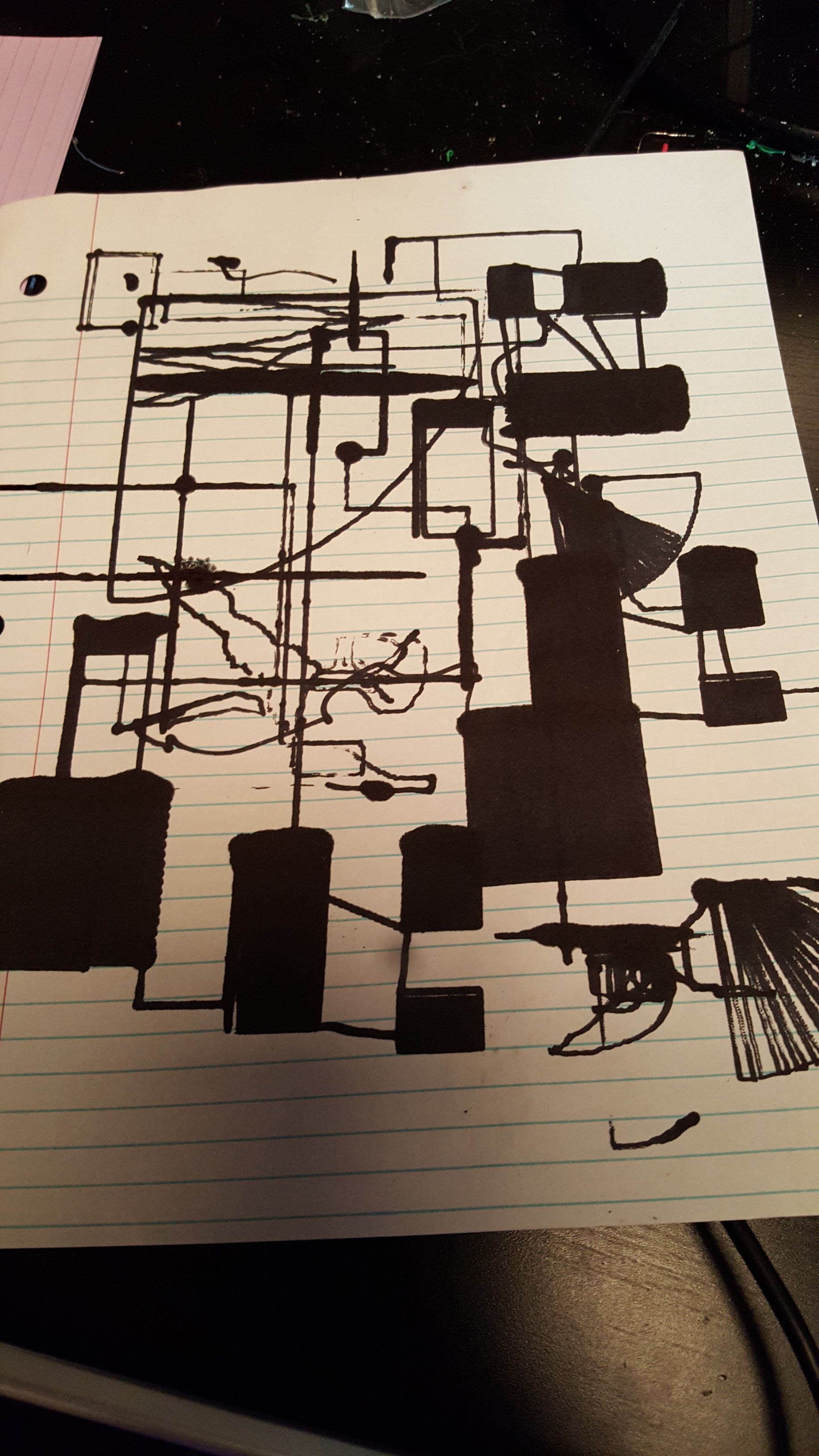
This board was taken out of my Delta style 3d printer, so obviously the firmware isn't quite ready to control the plotter. The firmware has proven to be one of the most painful parts so far. After many failed tests like this:
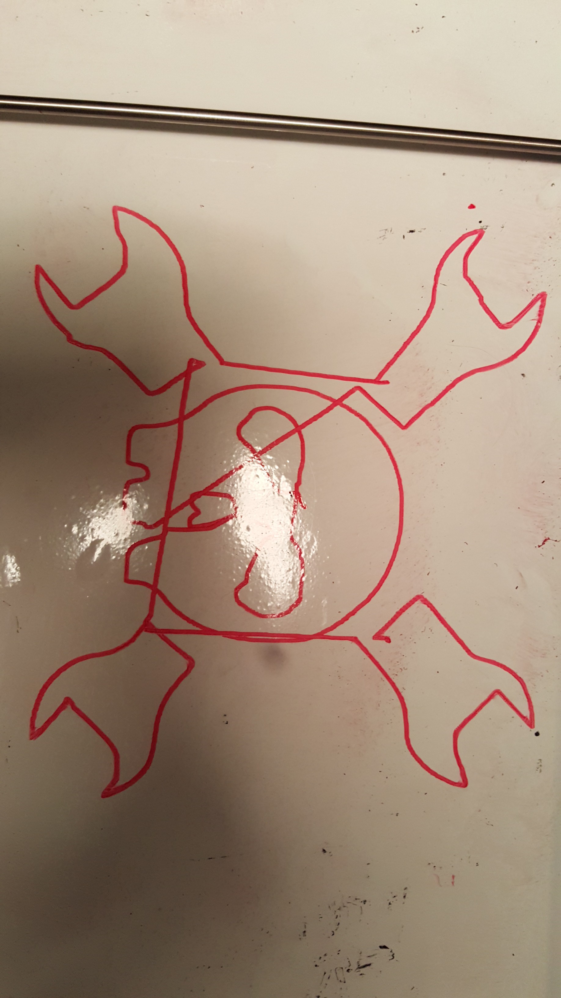
![]() I added a dry-erase board to it so I could just erase any problems and start again (I apologize for blurriness, my camera was acting weird, but you get th idea):
I added a dry-erase board to it so I could just erase any problems and start again (I apologize for blurriness, my camera was acting weird, but you get th idea):![]()
I rubber banded an expo marker to it, and was good to go. The only problem was that it was only drawing 1/4 of all of my images. I had no Idea what was causing it, it was not mechanical, or a problem w/ my Gcode, but I finally figured it out. I have the plotter configured without endstops, so I manually position the marker in the center of the image.In he firmware, I have my maximum distance in a positive direction at a really high number (1000) so I am not constrained by where I place the pen. The problem was when It want to plot quadrants 2, 3, and 4 (If you imagine the image's center point being placed on 0,0 on a coordinate plane), it would use negative numbers because it assumed the marker was at 0,0. The firmware had a limit that said it couldn't travel past 0,0 in any negative directions. I set that limit to -1000, and voila! it works:
![]()
Obviously there are still some problems. There is a lot of mechanical slop in the connection between the marker and the carriage due to myself using rubber bands, so not everything lined up. Also, when it travelled in certain directions, it would angle the marker at an angle that produced more friction, leading to some parts of the image being shrunk (very evident in the tips of the wrenches). In addition to all of those problems, It cannot pick up the marker when it moves to another part of the image, so it draws large lines through the whole image. Right now I am 3D printing some attachments that should rectify this. I found a small stepper to lift the marker up and down, so I am printing parts to attach it to the carriage, as well as a tool holder with the ability to fit all sorts of different writing implements. Next updae will happen when I install those!
-
Cable Management
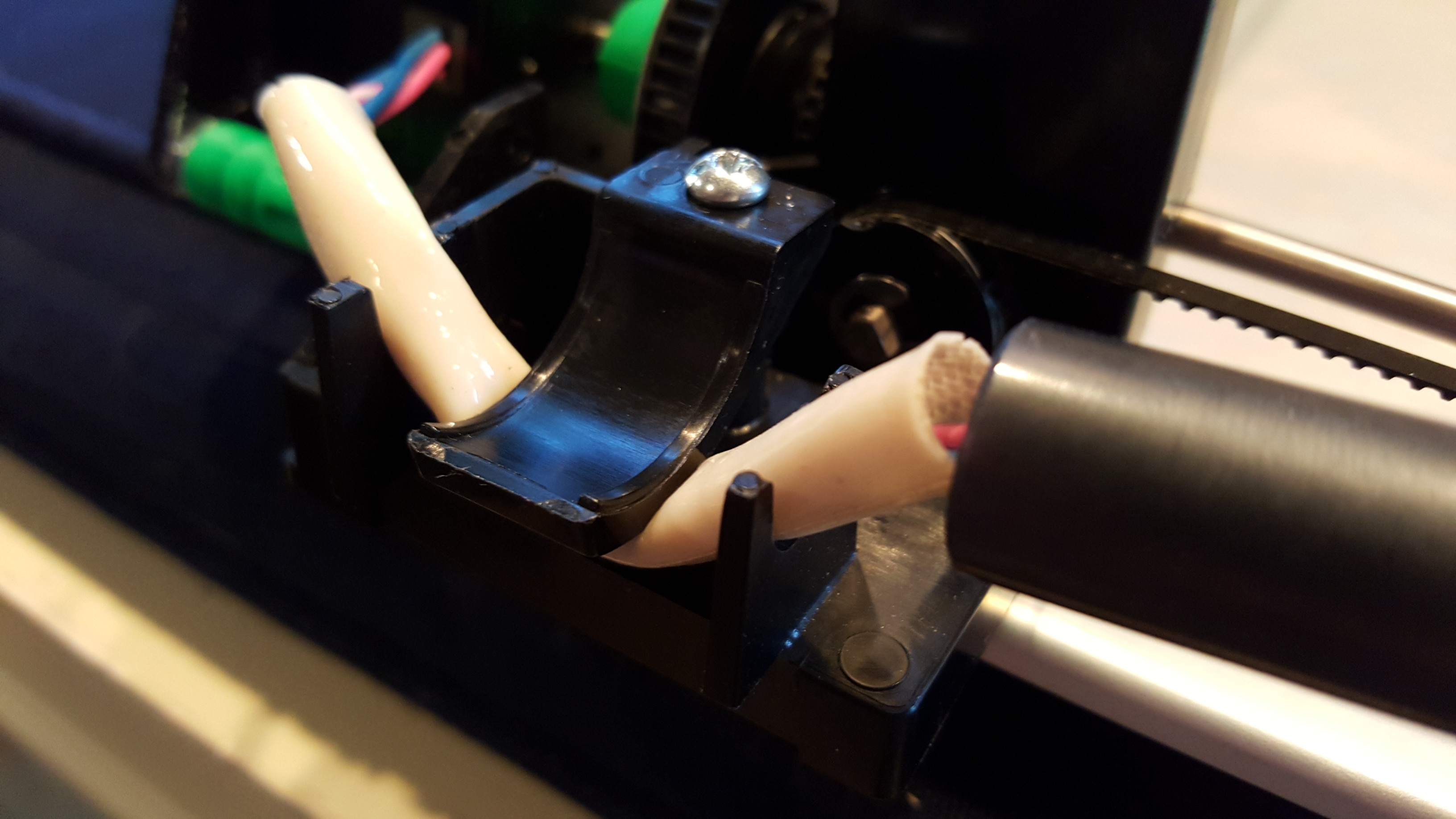
09/14/2015 at 23:22 • 0 commentsThis is going to be a rather short entry, parts to mount the second motor are still being printed, I ran into some issues with the mechanics not being symmetrical between the first and second motor, more details to come when everything is fixed. I just figured out that the cavity that held the DC motor previously and the retention clip can be repurposed into some nice little wire restraints to keep everything out of the machinery. Here is what it looks like up close:
![]()
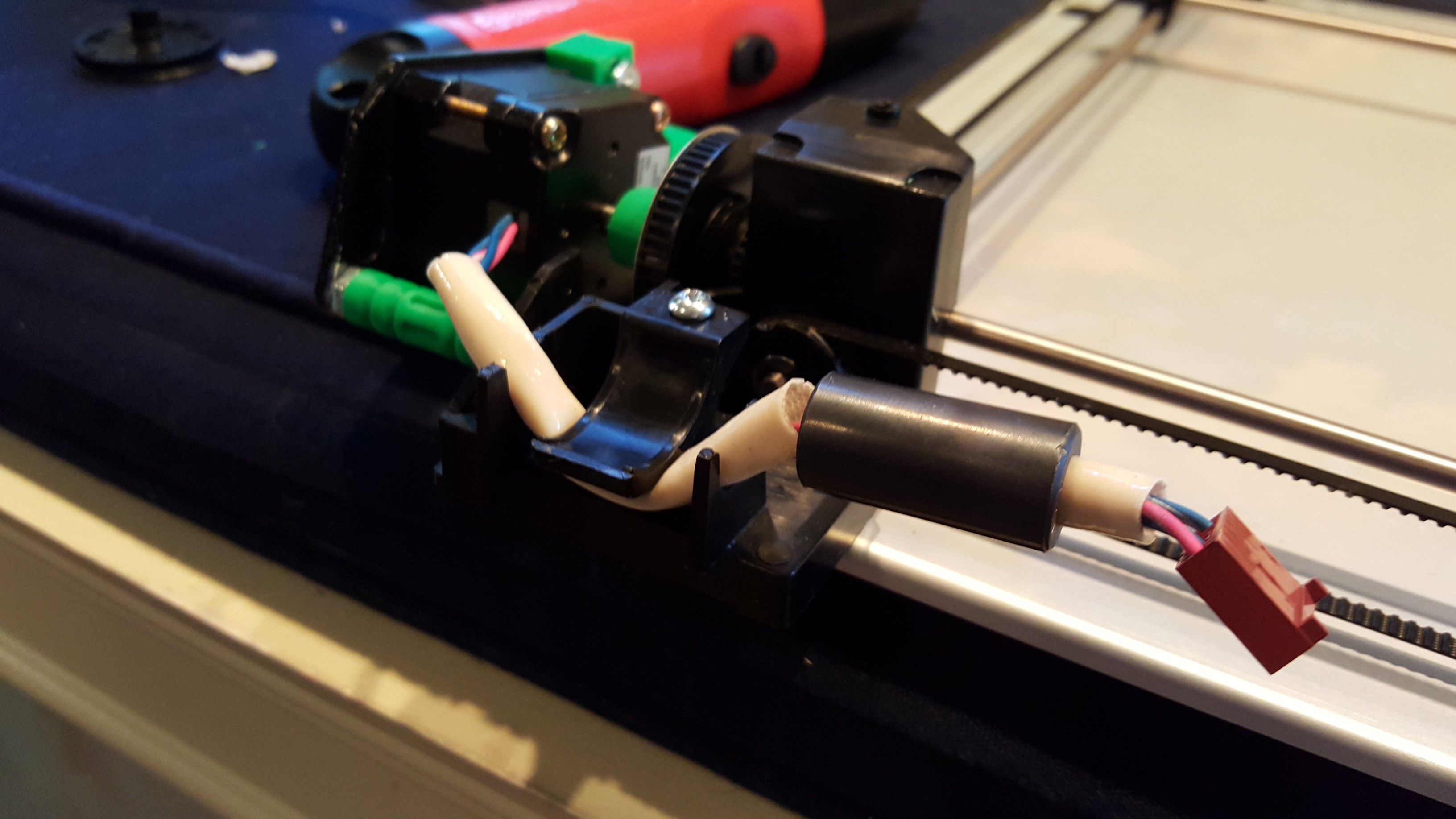
And from a distance:
![]()
-
The Stepper Motor is Now Secured
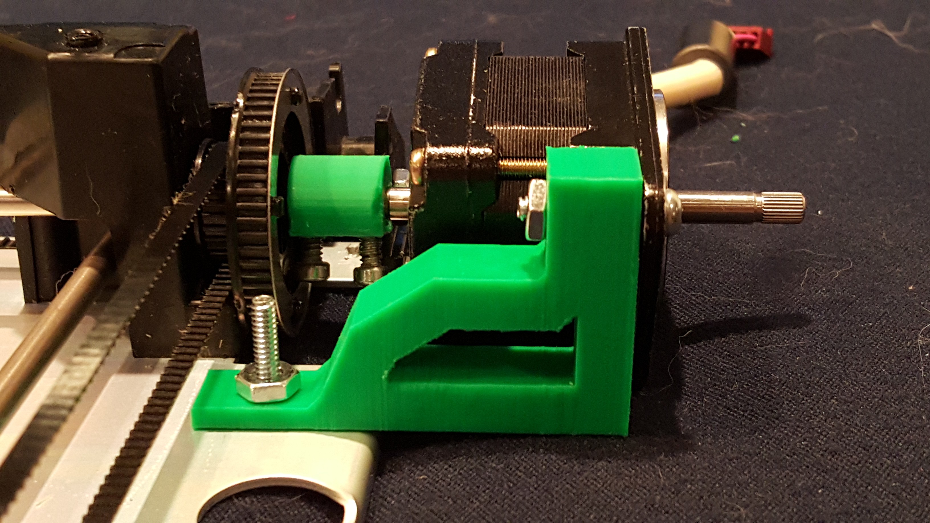
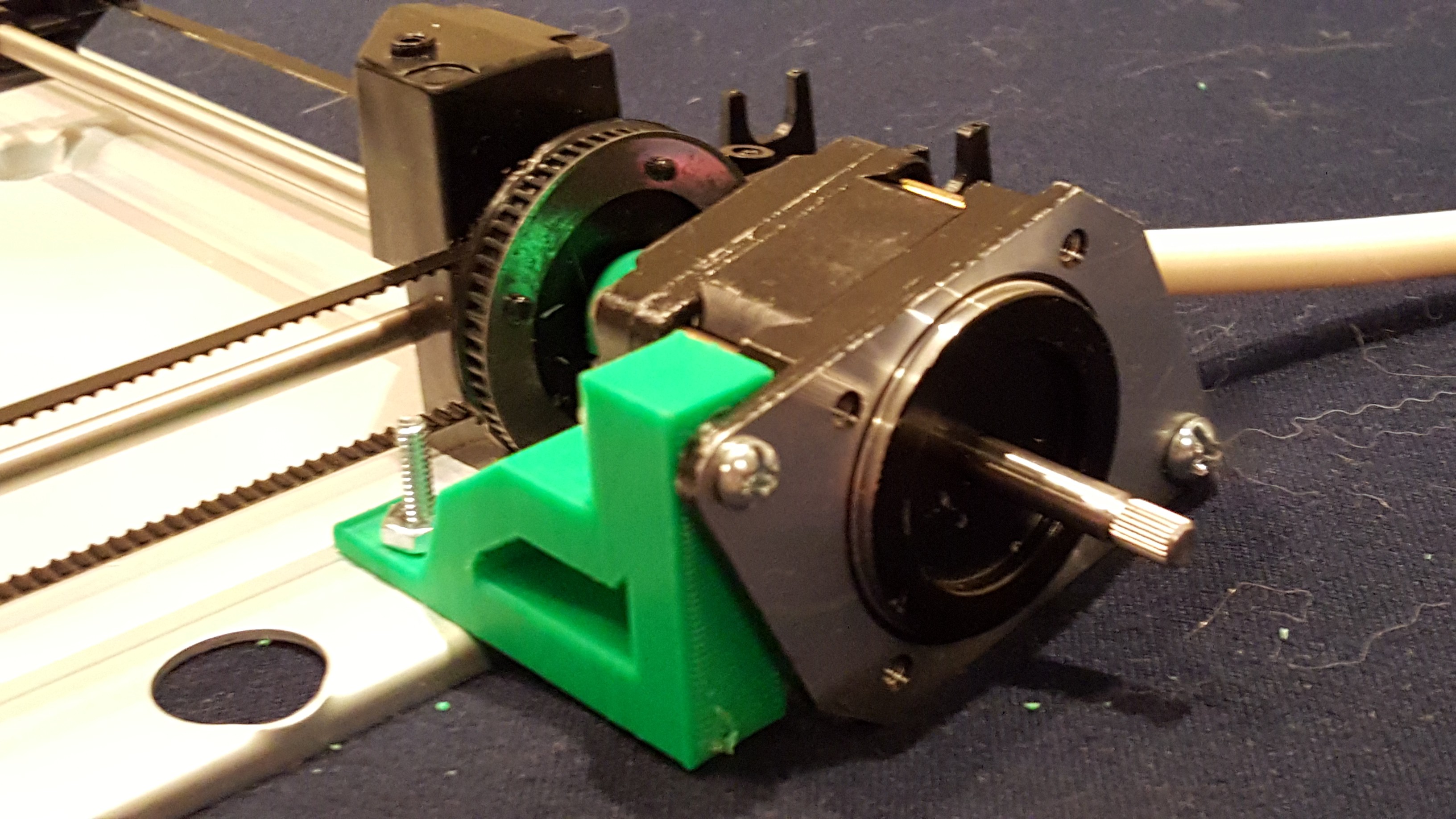
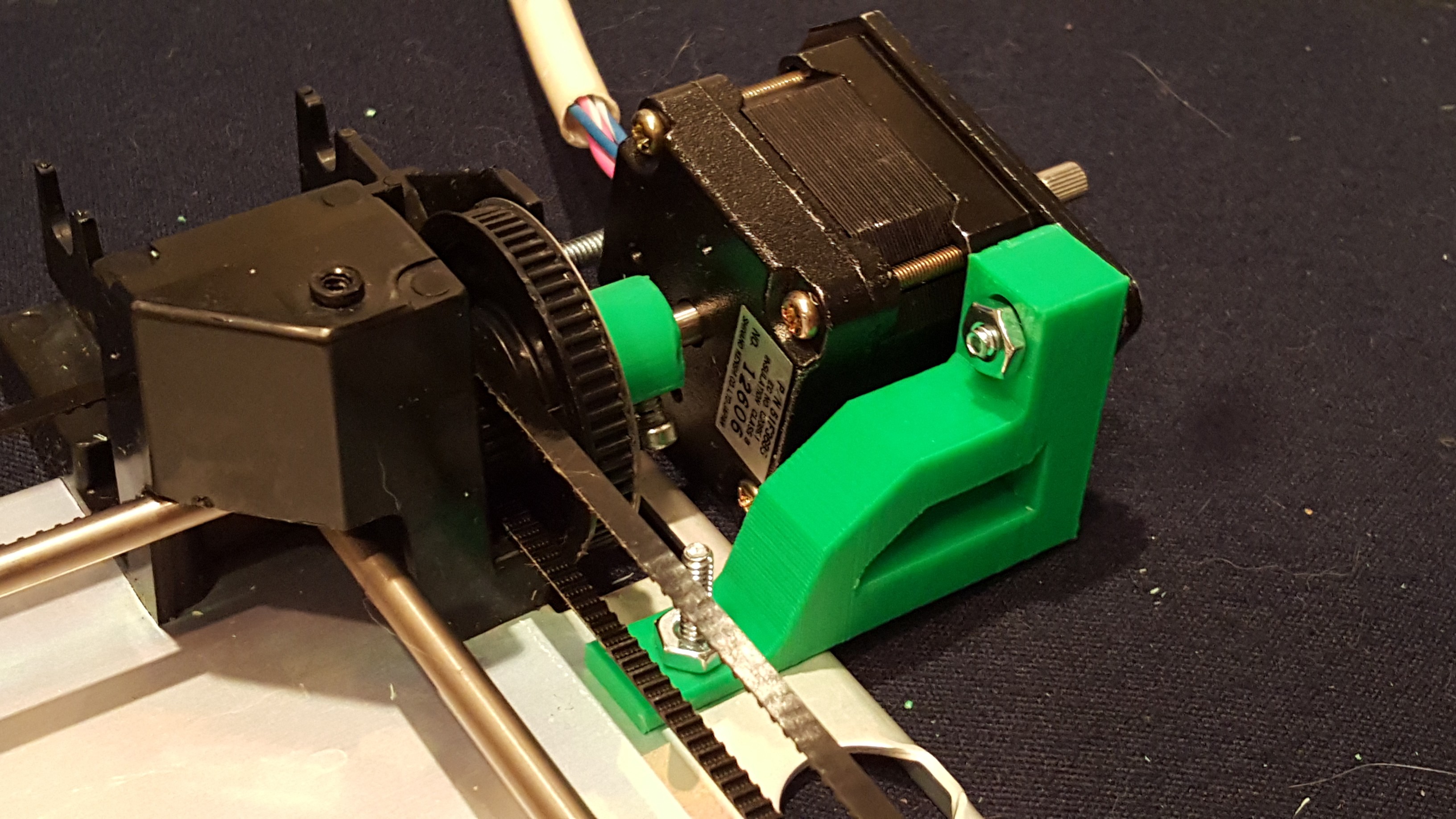
09/13/2015 at 23:54 • 0 commentsOne of the stepper brackets (for lack of a better name) finished printing, so I went ahead and installed it.
![]()
Here it is from another angle:
![]()
And this angle shows how little it interferes with the belts:
![]() This addition completely removes any play from the stepper motor, before this it tended to wobble around due to it only being held on by one point. There is room for improvement in the model, however, because while it functions nicely it is a little bulkier than it needs to be, and could definitely be streamlined. I may print a standoff to cover the exposed screw on the other side, mainly just for aesthetic purposes.
This addition completely removes any play from the stepper motor, before this it tended to wobble around due to it only being held on by one point. There is room for improvement in the model, however, because while it functions nicely it is a little bulkier than it needs to be, and could definitely be streamlined. I may print a standoff to cover the exposed screw on the other side, mainly just for aesthetic purposes. -
Motors Are Attached and Working
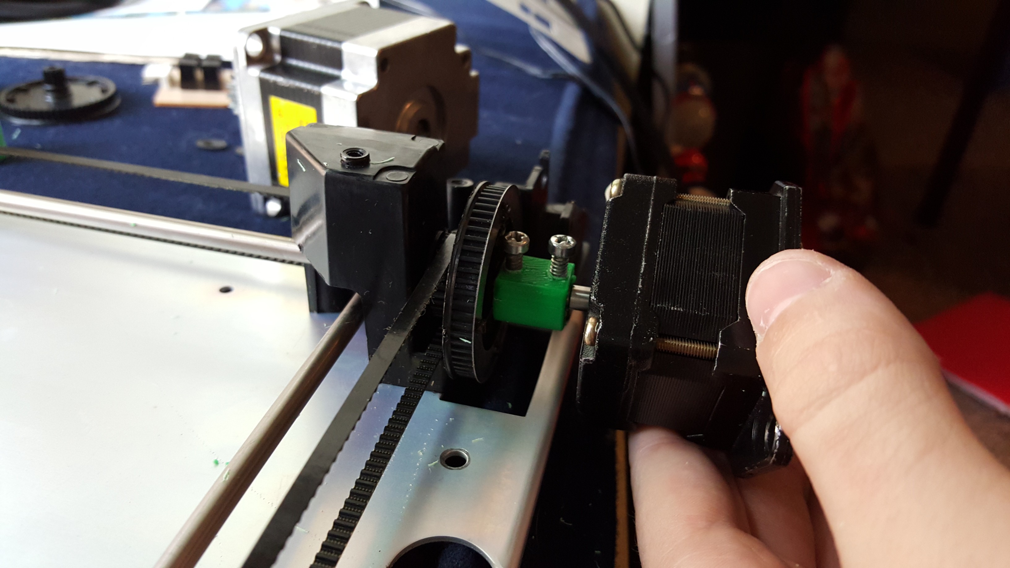
09/13/2015 at 20:19 • 0 commentsThe motor adapter pieces finished printing, and I have attached one of the motors.
![]()
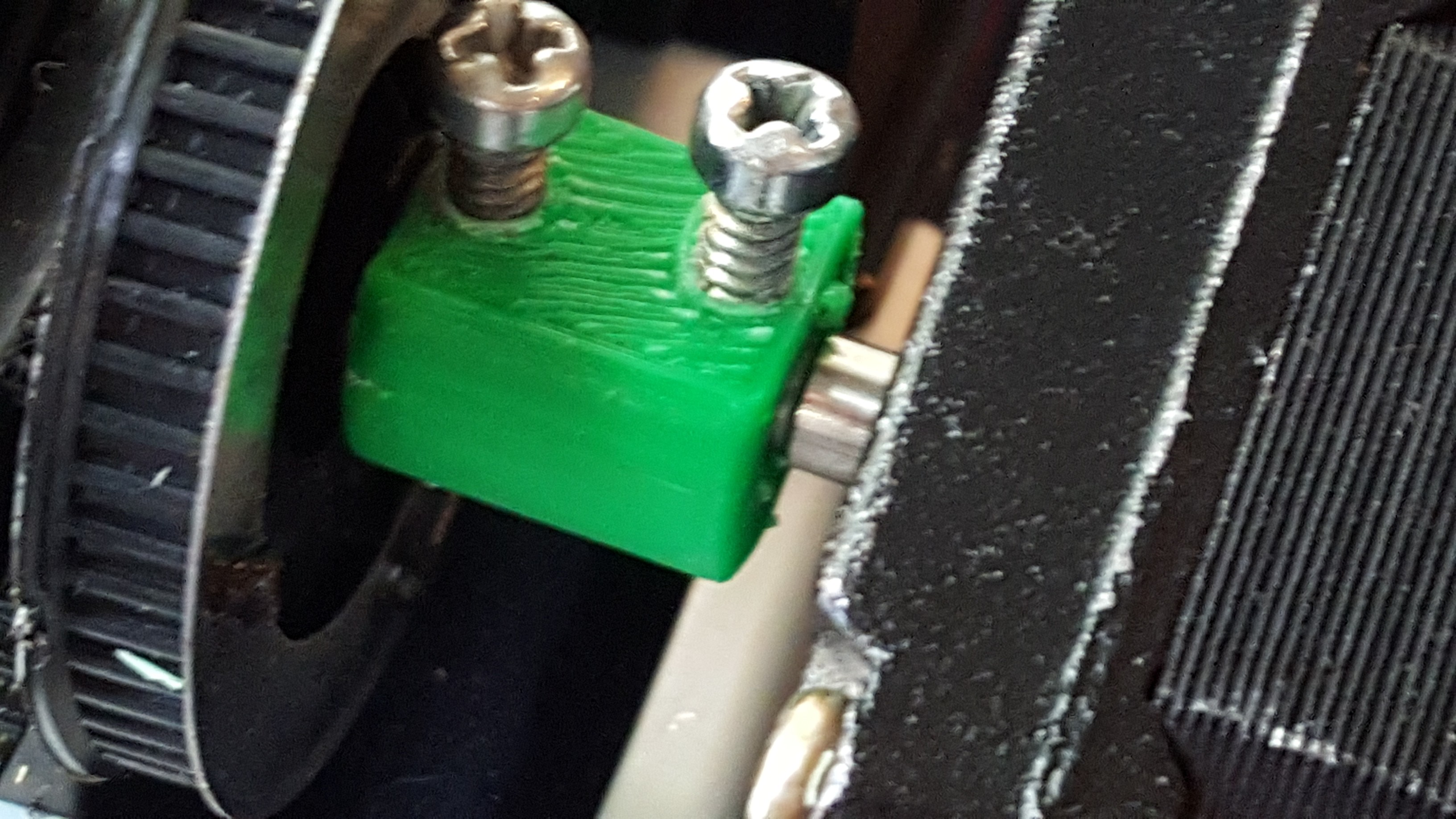
Here is a close up of the actual adapter piece:
![]()
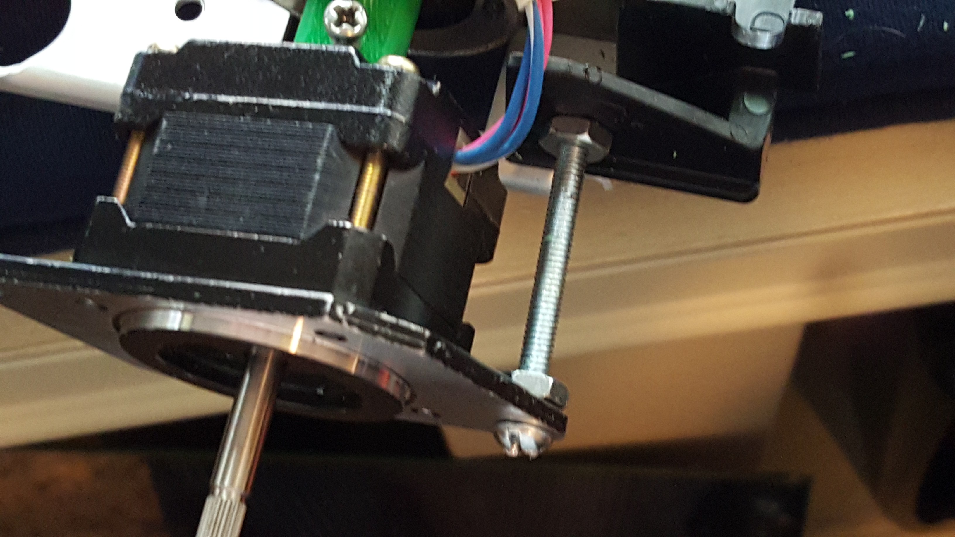
And this was my quick and dirty way of mounting the motor to the rest of the assembly:
![]()
I hooked up the motor to my Arduino for a quick function test, and it moves! There is very little torque, but it is just fine for a plotter. I doubt I will be attaching a Dremel or anything like that anytime soon, however :) Next up, I have to design a better way to mount the motor.
-
It Begins!
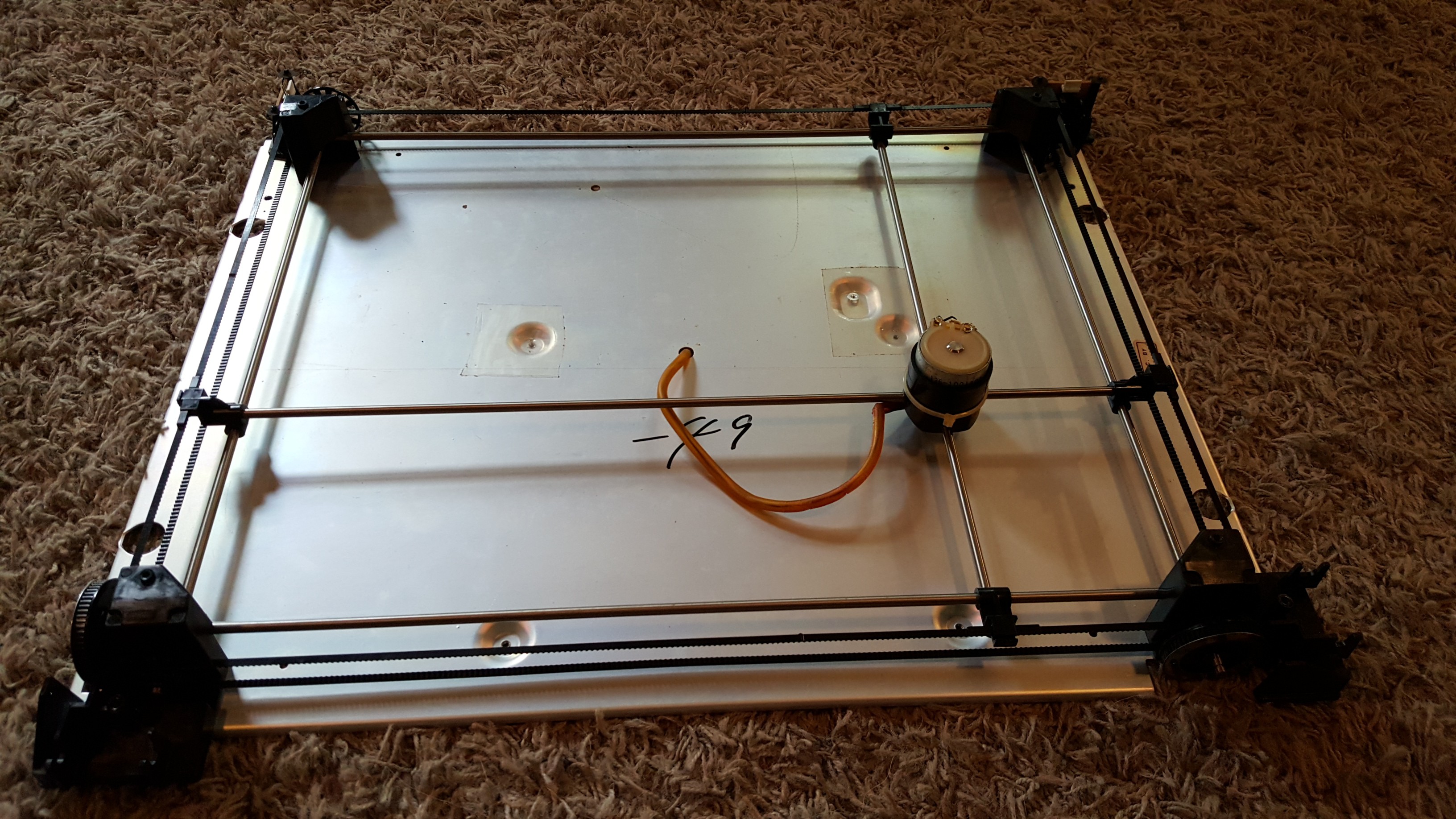
09/13/2015 at 16:47 • 0 commentsI recently received a broken robotic chess game from a friend to do with as I wished. It was very old, and when disassembled did yield a variety of interesting components. The most useful piece was the assembly that moves the electromagnet around. With very little modification, they appear to be able to be easily convertible to a CNC machine.
![]()
I removed the weak DC motors/rotary encoders that it used previously, and I am currently 3D printing adapters for some stepper motors I have. Luckily the rods that connect to the belts are the same diameter as my stepper motors (+/- .1 mm), so designing couplers could not be easier. The next step is to mount the new motors one the couplers are done printing
CNC Plotter From Robot Chess Game
A broken robotic chess game is easily turned into a CNC plotter. Can be cheap, depend on what you have.
 I added a dry-erase board to it so I could just erase any problems and start again (I apologize for blurriness, my camera was acting weird, but you get th idea):
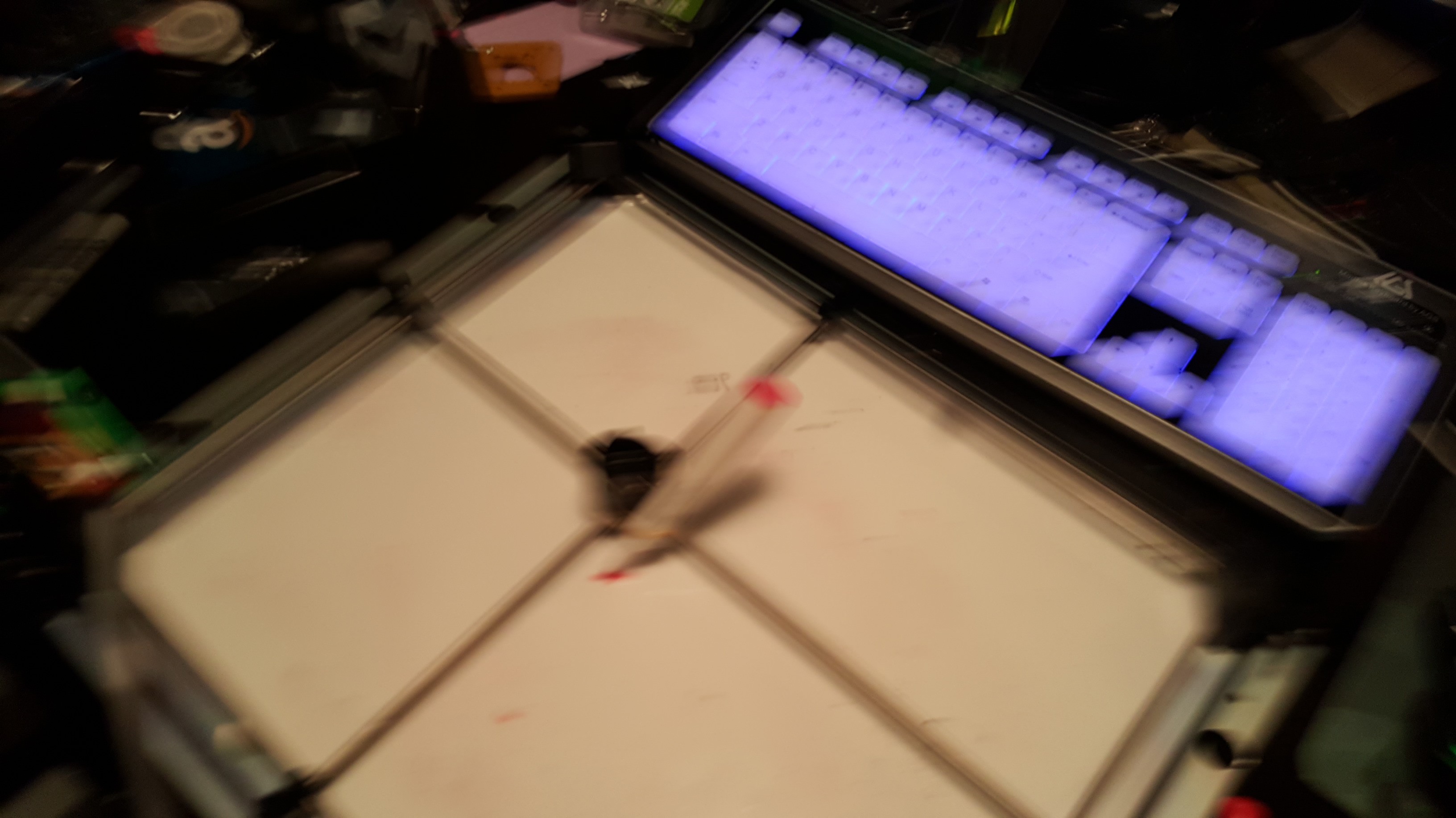
 This addition completely removes any play from the stepper motor, before this it tended to wobble around due to it only being held on by one point. There is room for improvement in the model, however, because while it functions nicely it is a little bulkier than it needs to be, and could definitely be streamlined. I may print a standoff to cover the exposed screw on the other side, mainly just for aesthetic purposes.