==Background
First up, a few links to existing stuff on the subject.
Air Speaker - A website devoted to massless loudspeakers
Stable sound wave generation in weakly ionized air medium (scientific article)
EFA Loudspeakers - they claim their loudspeakers can make 130 dB SPL, corresponding to sound pressure of 60 Pa. I doubt it, because it means at least 1.2 kg of thrust due to constant wind (HUUUGE).
Ion wind sound emitter is made of two major pieces: a blower, and a high-voltage-output power amplifier, which requires a high-voltage power supply.
==System components (sub-projects)
Blower
The blower is the essence of the project, which is just some metal and some insulator parts put together to generate ion wind when high voltage is applied
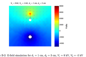
#IW blower theory. Some calculations of ion drift zone, the region where the actual wind is created.
#IW blower 1 - the first blower that was able to make some sound.
#IW blower 2 - pipe - the most successful one so far. It is a wire stretched in a half-pipe-shaped other electrode.
#IW blower 3 - multistage - attempt of multistage, multielectrode blower.
#IW blower 4 - 3d printing test - testing compatibility of ion wind and 3d-printed stuff.
High-voltage power supply
At the beginning, I was using a CRT-transformer based high-voltage power supply, with a bunch of capacitors and a string of standard 1kV 1A diodes used as zener shunt voltage regulator.
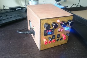
Later, I've built a long diode-capacitor voltage multiplier, which is silent, and generates a large sequence of high voltage potentials (positive and negative, up to +/- 20 kV / 40 kV between extremes). Having a sequence of potentials (including negative) is very handy for multi-electrode experiments.
High-voltage audio amplifier
Again, I had two generations here. One was just a microwave oven transformer connected to output of a regular audio amplifier. I won't even bother documenting it, but it was good enough for proof-of-concept experiments.
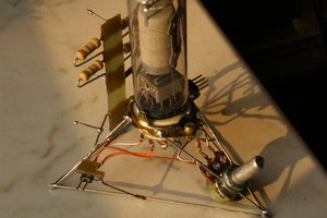
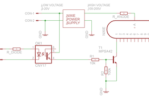
It is based on a high-voltage vacuum tube, and has an optional feedback for getting voltage-drive output. Vacuum tube was chosen not because of audiophile reasons, but rather due to the tubes being extremely tolerant to high-voltage abuse. A single spark can easily kill a transistor, yet to kill the tube, one has to supply substantial power for substantial time to melt the anode, which is plain impossible with my power supplies.
#High-voltage oscilloscope probe is an essential part of the feedback circuit of the amplifier.
==High-voltage safety
Voltages in this project can reach 40 kV. This much voltage stored in some substantial capacitance like I have in my high-voltage power supply, can potentially cause death.
I recommend reading this: http://www.instructables.com/id/Work-safely-with-high-voltage/
Here are some rules that I'm trying to follow when doing this.
1. Make sure the low-voltage part doesn't charge up to high-voltage potential, by ensuring it is earthed. Make sure it is safe to operate the on-off switch.
2. Make sure the operator (you, me) is NOT earthed. This should limit the zap you get if you accidently touch the point at high potential.
Don't wear an antistatic wristband, as the 1M resistor in it is not a high-voltage resistor. It can be broken down when you get the zap, effectively directly earthing you.
3. Operate the thing with one hand only when it is powered up. Again, this should limit the zap in case you get one, to just the hand, with almost no current passing through heart zone.
 DeepSOIC


 Christoph
 outlawpoet
This is a great modern project similar to early work on ion speakers and plasma speakers on https://massless.info (the new version of the airspeaker.co.uk website mentioned). From the 1950's Dr. Tombs developed a corona wind speaker https://massless.info/Tombs.html