Close
0%
0%

IW blower 2 - pipe

Ion wind blower, second model

Similar projects worth following
This is one of a few ion wind blowers I've made for my "Ion wind loudspeaker experiments" project. See link in left column.

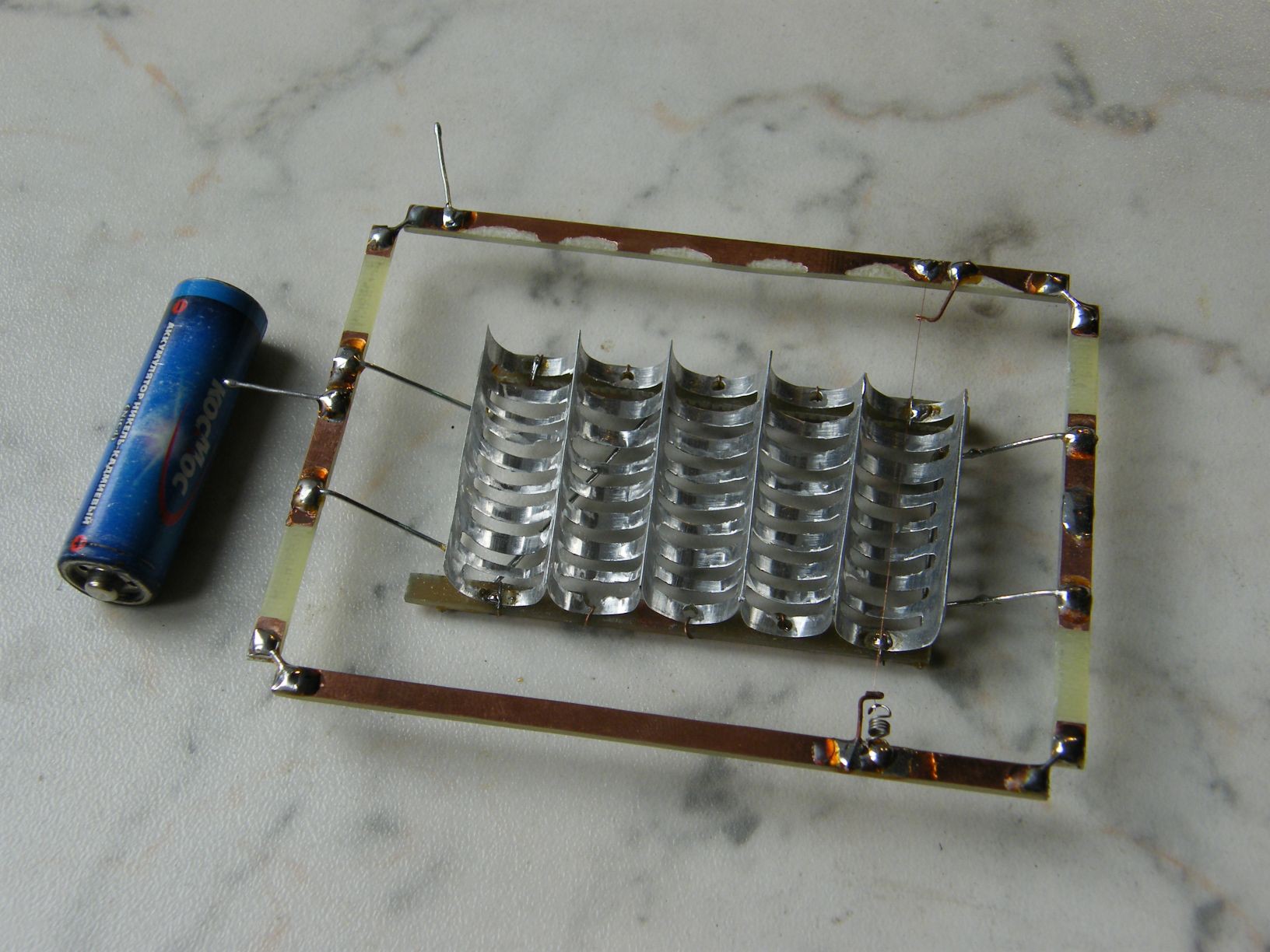
Corona discharge around a thin wire puts ions into air. Then, ions drift towards the other electrode, shaped like a half-pipe. As the ions impinge the air, they transfer some momentum to it, that is, creating pressure.

This is my most successful blower so far, both in terms of sound emission, and blowing. It is almost hiss-free, withstands abuse (sparks and arcs) well.

The corona wire is a 0.2 mm nichrome wire. The pipe is like a AA battery in diameter, with slots dremeled through it to let the airflow through.

This project is a subproject of #Ion wind loudspeaker experiments.
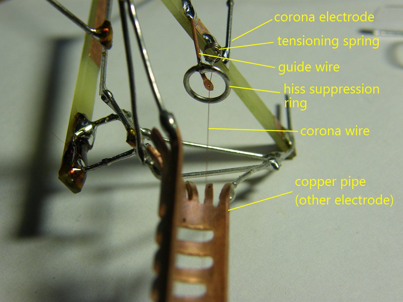
Guide wire is just a piece of soft copper wire, that is easily bendable to adjust the position of corona wire in the pipe.

Hiss suppression ring was added after observing intermittent corona discharge from tip of the guide wire. The ring eliminates the intermittent discharge by screening most of the electric field. This made the thing very silent.

Insulating structural elements are simply pieces of FR4 PCBs.

Both the corona wire and the pipe are isolated from ground, so high voltage can be applied in any polarity. This makes the thing potentially lethal to touch when it is operating. But it isn't a good idea to touch it even if the pipe was grounded, because all the high voltage stuff is exposed anyway. This is an experimental prototype, anyway.

Polarity

Note that I can't say cathode and anode to label the electrodes, because the blower can be connected both ways, and will still be making the wind in the same direction. It is the sign of the ions in the drift region that changes (it corresponds to the sign of corona electrode).

Also, the appearance of the corona discharge changes with polarity. If positive corona (corona around +V), the glow is smooth all the way along the wire. If negative is applied to the wire, the corona discharge forms a pattern of dots on the wire.

I haven't noticed any performance difference because of this, but I believe positive corona is better. Because positive corona means positive charge carriers in drift zone. Positive charge carriers can only be ions, while some of the negative charge carriers can be plain electrons, which are extremely lightweight, and thus are unable to push the air.

And, positive coronas apparently produce less nasty gases like nitrous oxide and ozone.

==Characteristics

I-V-W curve
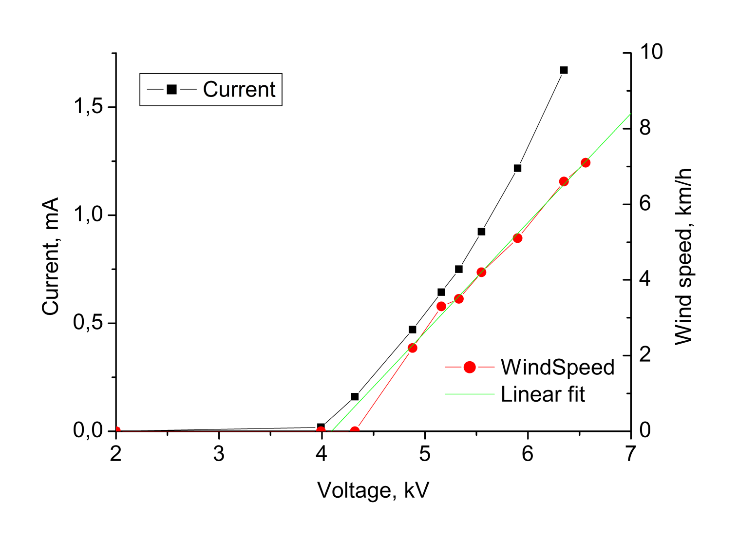
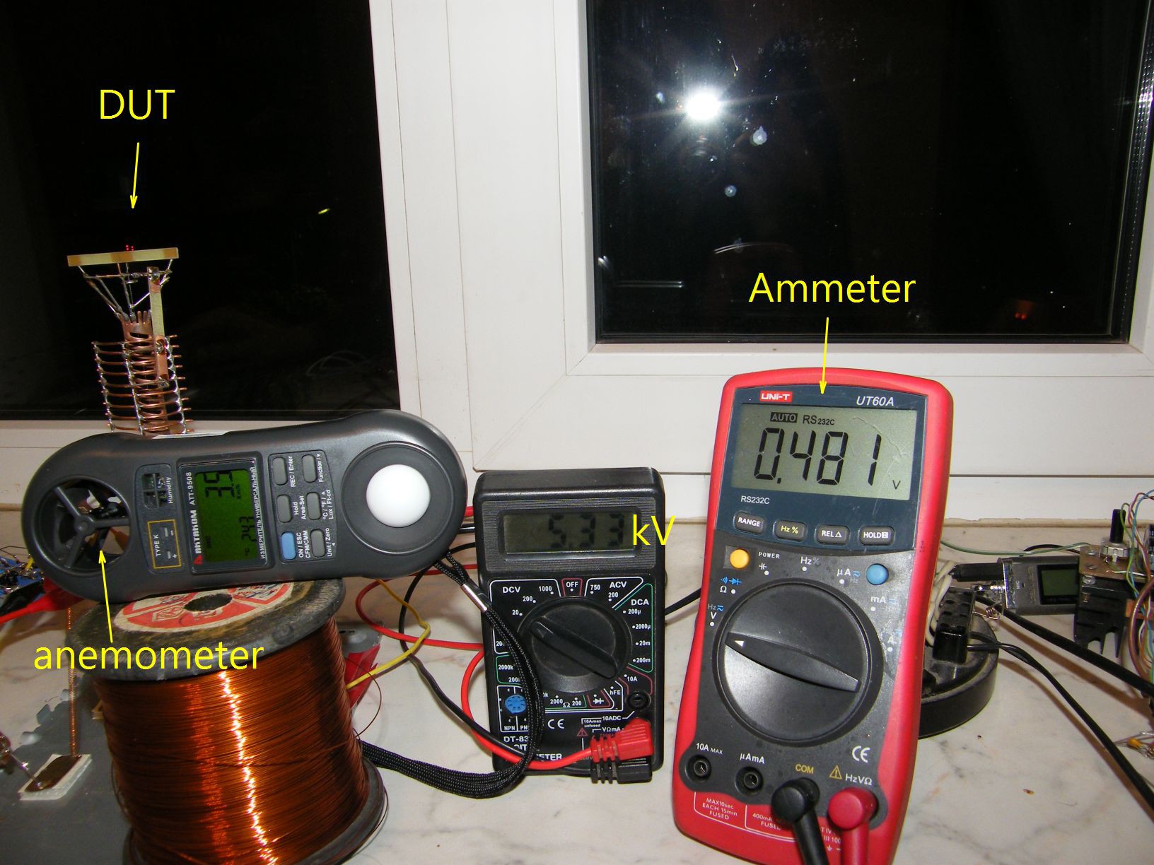
Wind speed measured by axial turbine anemometer, placed about 100mm behind the blower, at the exhaust side.

The result is that the wind speed is in rather linear relationship with applied voltage (I expected it to be linear on current, basing on some calculations). is the wind speed proportional to pressure? I hope so, but I'm not really sure about it.

Maximum voltage on the graph is limited by the onset of sparking. The lack of any current below 4kV is because of no corona discharge at those voltages.

Frequency response
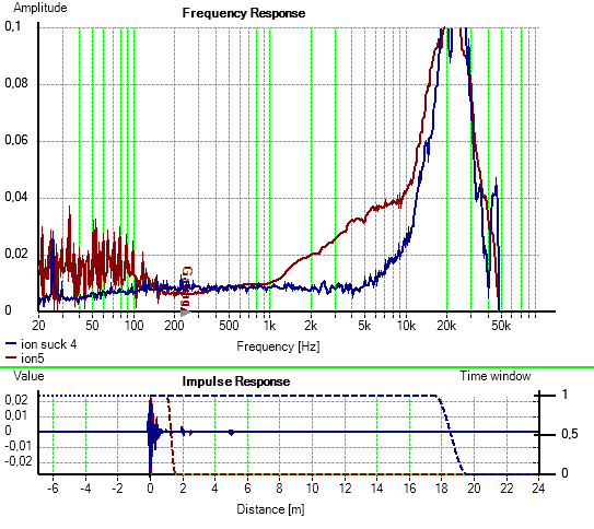
Blue trace is at suction side. Brown trace is at exhaust side. I think the low-frequency noisy spectrum is caused by wind making noises itself.

This frequency response was measured with voltage-mode drive. It was done through a sound card of a PC with help of HOLM Impulse software. Results are interesting.

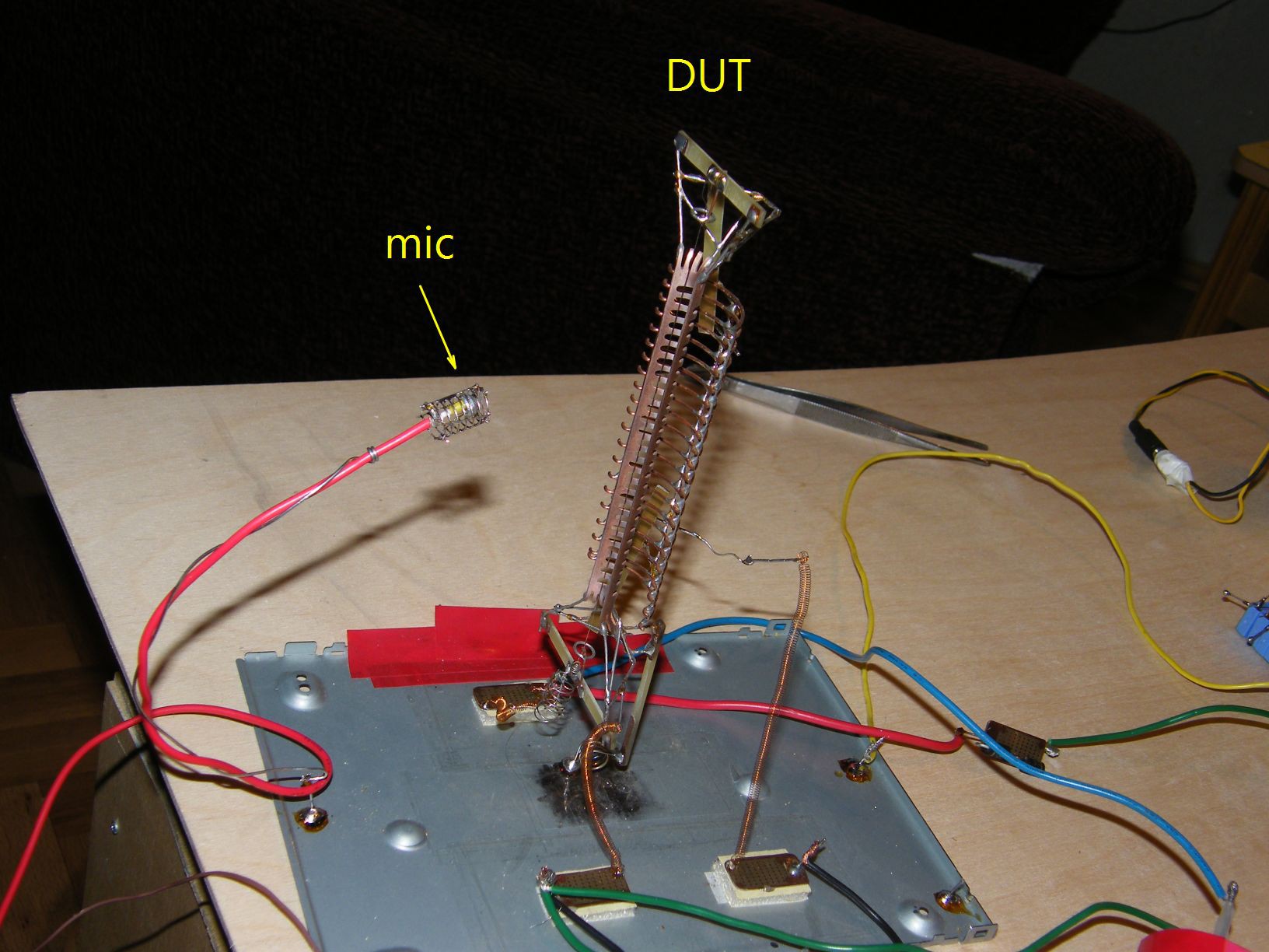
Note that this is the frequency response of the system as a whole. That includes the soundcard, the amplifier, the blower, the microphone and the soundcard again. I haven't tested the amplifier alone, which may be responsible for the high-frequency peak around. The microphone is a tiny electret mike ripped off some device. These mikes have good flat frequency response, typically. I put it in a metal cage to give it some extra protection from ions in the wind.

==video

This is one of the first attempts to make some sound with this blower. I used negative corona here, because the living dots look much cooler than even glow of positive corona.

Please excuse the shit quality, which is mostly thanks to the quality of camera. The camera didn't record the high-frequency content, but the recording actually sounds BETTER than it was in reality, because it was accompanied by intense high-frequency whistle from a far-from-perfect CRT power supply. That whistle (12 kHz or so) was completely eliminated by camera's sound recording system.

blower 2 model.FCStd

A FreeCAD-0.18 project where I made the model. If you just need the model, please use STEP file instead, as this one contains a lot of creative mess.

fcstd - 624.53 kB - 01/19/2019 at 23:14

Download

blower 2 model.step

An approximate model of the blower

step - 2.23 MB - 01/19/2019 at 23:14

Download

  • Clarifications

    DeepSOIC01/19/2019 at 23:22 0 comments

    I was contacted by a person doing research on ion wind. After a lot of communication, it turned out that I was using different corona wires for VA-curve measurement and for sound measurement. For VA, the wire was likely 0.08 mm Cu.  For frequency response, it was 0.19 mm nichrome. It's hard to be sure (so many years have passed), but I dug out some photos, and the wires are obviously different

    I have also made a crude CAD model of the thing. Find it in project files.

  • Previous version to this one

    DeepSOIC09/30/2015 at 17:01 0 comments

    It didn't work well, because of numerous coronas on edges of large electrode. Was hissing a lot.

    Current tube blower is a result of refinement of this model.

  • Measuring frequency response

    DeepSOIC09/30/2015 at 10:07 0 comments

    There was an accident during this.

    The blower is mounted to the base via a spring. That gives visual feedback for the amount of thrust it produces (not much). Because of no dampener, the thing oscillates easily.

    When I wasn't careful enough switching it on, it got wobbling so far that it touched the microphone. Then comes a huge spark (mike is grounded through the soundcard of the PC). That spark made my PC reboot instantly, as if I had pressed reset button. And then I was shocked as if I was hit by that spark, when I found out that the sound card is intact! Phew!..

  • Measuring I-V curve

    DeepSOIC09/29/2015 at 22:11 0 comments

    Ammeter is measuring a voltage across a diode, that was later converted to a current by calibration measurement separately. Diode (actually, two inverse-paralleled diodes) was used instead of a common resistor way of doing it, because resistor will fail to protect the multimeter in case of a spark across the blower. Diodes are very hard to blow open, they typically die blown shorted. These 1A ones survived sparking no problem whatsoever.

View all 4 project logs

Enjoy this project?

Share

Discussions

greenaum wrote 09/30/2015 at 20:53 point

Actually now I've thought about it some more, I realise the PC is only for listening, not producing the sound.

In that case, maybe hide the mic behind a piece of wire mesh, connected to earth, or to system ground? Maybe even a small wire cage. Just to provide a more attractive path for those stray, conductive ions! And perhaps a cheap USB sound card, just to add a few more components between the mic and the motherboard, normally a mic will go straight to the Southbridge, or whatever they have nowadays.

A new video I think would be better, presume you've made progress in the last 5 years!

  Are you sure? yes | no

DeepSOIC wrote 09/30/2015 at 21:14 point

"presume you've made progress in the last 5 years!" Not much =(. x

The project is close to abandoned. I haven't touched it for full two years already. But now that I have some more cool tech, such as 3d-printer, digital scope, signal gen, etc, I think I can move on.

As for soundcard: cheap USB thing won't do, as I wanted to cleanly cover 20kHz and slightly above. Sound Blaster X-Fi that is in my PC is capable of high sample rates (96 kHz). In contrast, Realtek in my notebook, although it claims to support 96 kHz, actually does not (I did try getting above-20kHz ultrasound signals out of it, but it simply chops them off with a brickwall filter).

  Are you sure? yes | no

greenaum wrote 09/30/2015 at 23:14 point

Groovy! That Realtek does sound a bit crap. 96,000 samples, made of 48,000 identical pairs! What a rip, if they weren't pretty much the only embedded sound chip that exists in PCs, somebody would complain! 

So how does your speaker sound in general? You said you got the hiss out of it. How loud is it? Any idea on efficiency? Quality looks fine up to 5KHz, isn't most stuff past that just cymbals etc? Which are not too far from noise anyway, so you might not notice too much. Even harmonics from guitars and pianos I doubt would matter much past there.

Would filtering on the source side help much with the spike past 5KHz? IE just reduce that a lot from the source. I realise cheap MP3 players don't often have graphic equalisers, but you could treat the MP3s on a PC first.

  Are you sure? yes | no

DeepSOIC wrote 10/01/2015 at 11:05 point

Well, actually, Realtek isn't bad for sound. And I can't fault it by ears. Being unable to output anything above 20k isn't a problem for sound.

You may find it interesting, that up to 19 kHz, the realtek maintains clean sine wave output, even though the full wave is represented by just a bit more than two points. All it tells me is that its brickwall filtering works very well. I was literally blown away when I saw it. I didn't know beforehand that modern audio DACs are so advanced.

Sorry, it's in russian, but you should get something from just the image =)

  Are you sure? yes | no

greenaum wrote 09/30/2015 at 15:01 point

Oh, option 2... cheap MP3 player as sound source. Even easier!

  Are you sure? yes | no

greenaum wrote 09/30/2015 at 15:01 point

Wow! But I can't be the only one wondering, what does it sound like? You have to make a video!

For the sound, might be wise not to plug directly into your PC, it's just asking for trouble! HV leaks everywhere! Maybe some sort of opto-isolator? Perhaps the easiest, if not cheap, would be using an optical audio out from a soundcard supporting it, and an amp that inputs it. Of course the amp would still be at risk, but amps are simpler than PCs, and they're designed to handle power.

  Are you sure? yes | no

DeepSOIC wrote 09/30/2015 at 15:52 point

I needed a PC for frequency response measurement, because it simplifies the process greatly. Otherwise, I did yes exactly what you suggested - a cheap mp3 player =)

Video! yes, I have one (quite crappy though, recorded about five years ago), thanks for reminding!

  Are you sure? yes | no

Similar Projects

Does this project spark your interest?

Become a member to follow this project and never miss any updates