AVR
AVR-
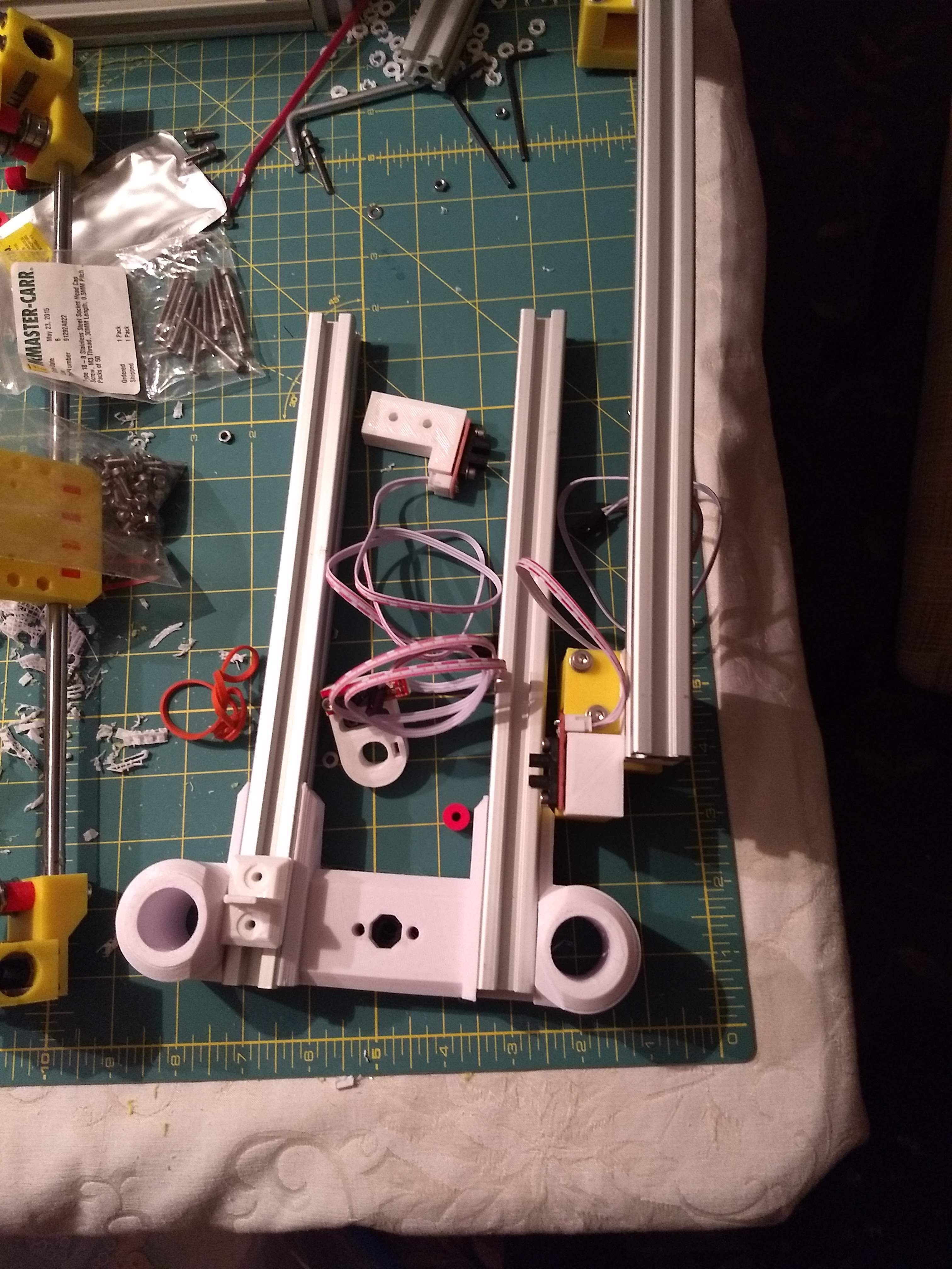
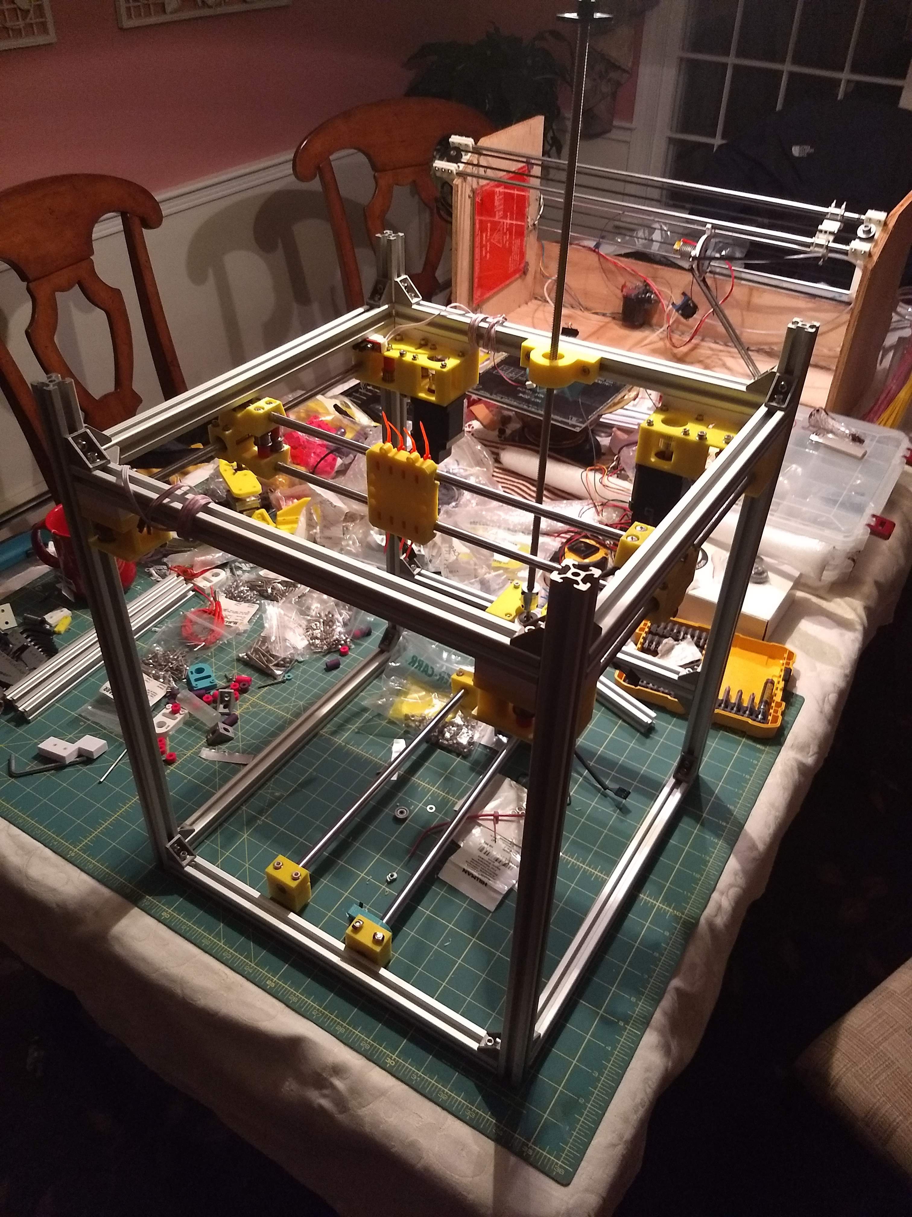
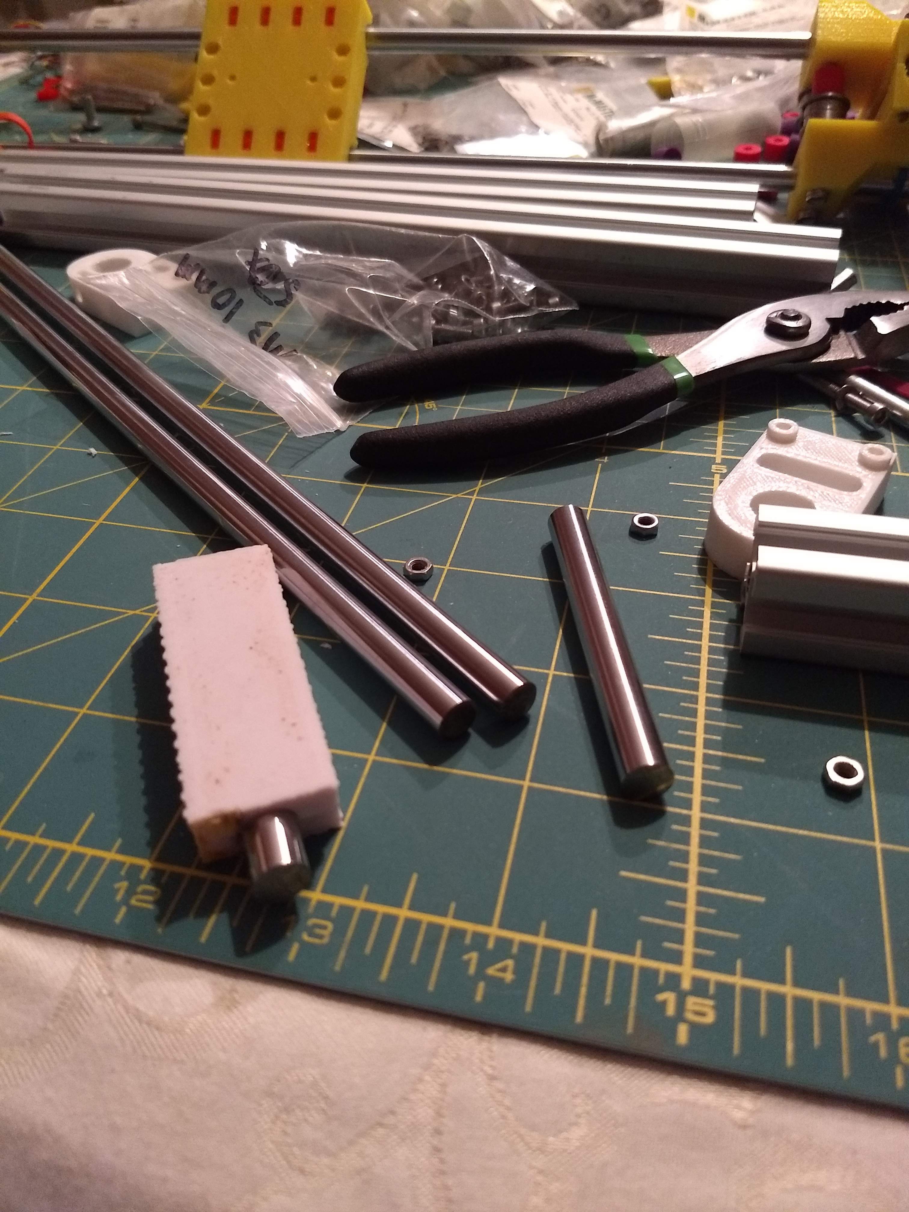
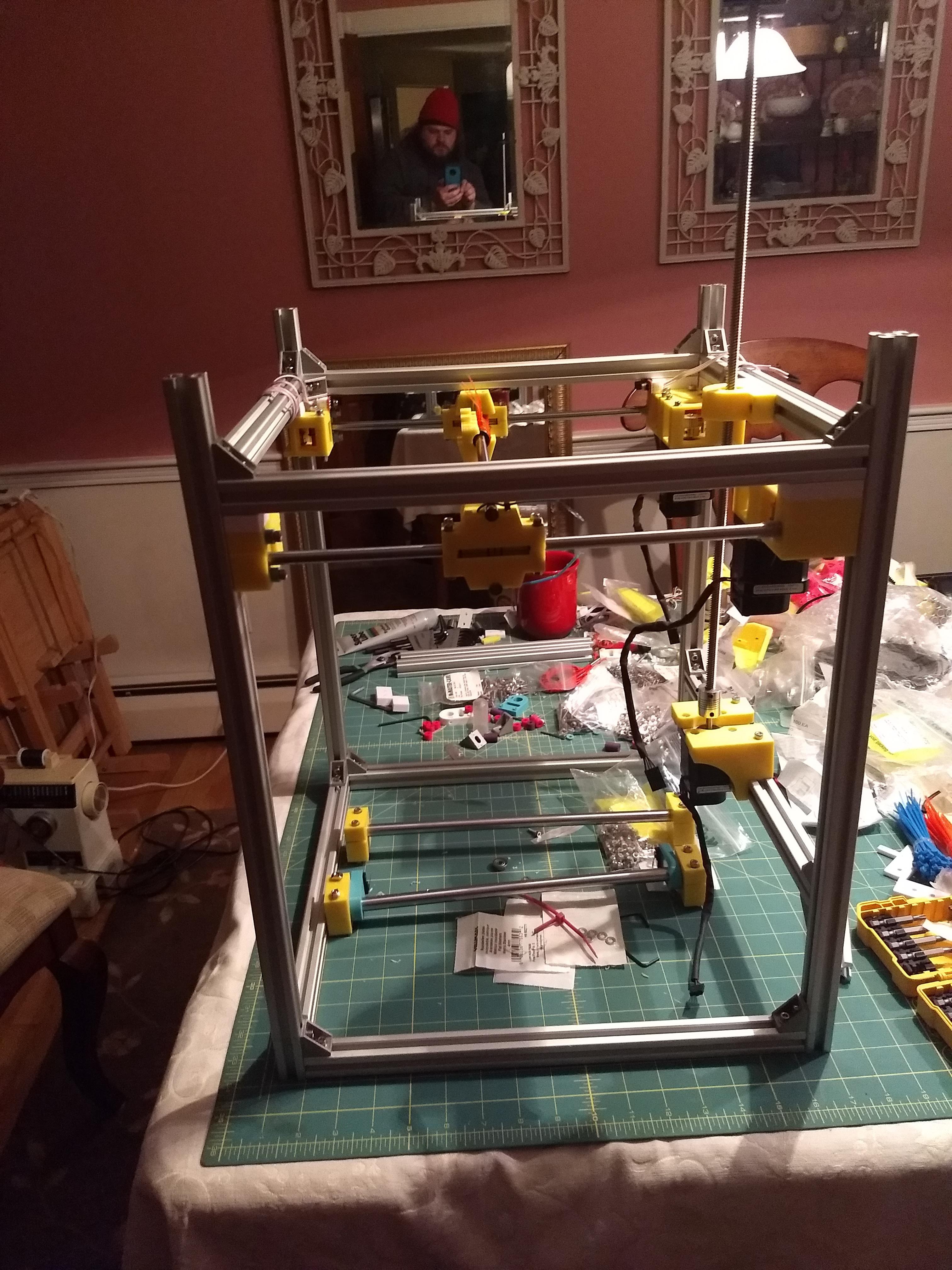
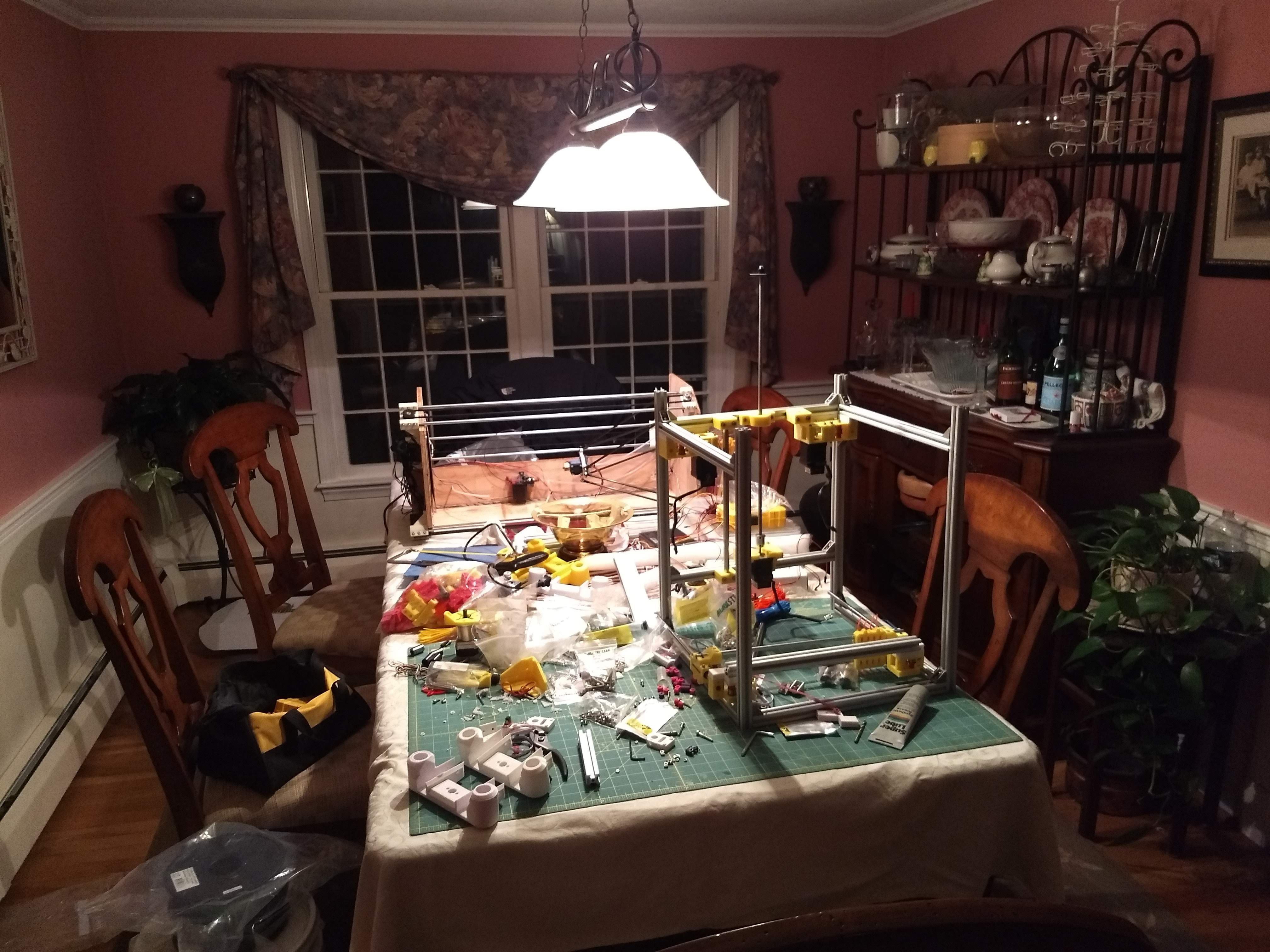
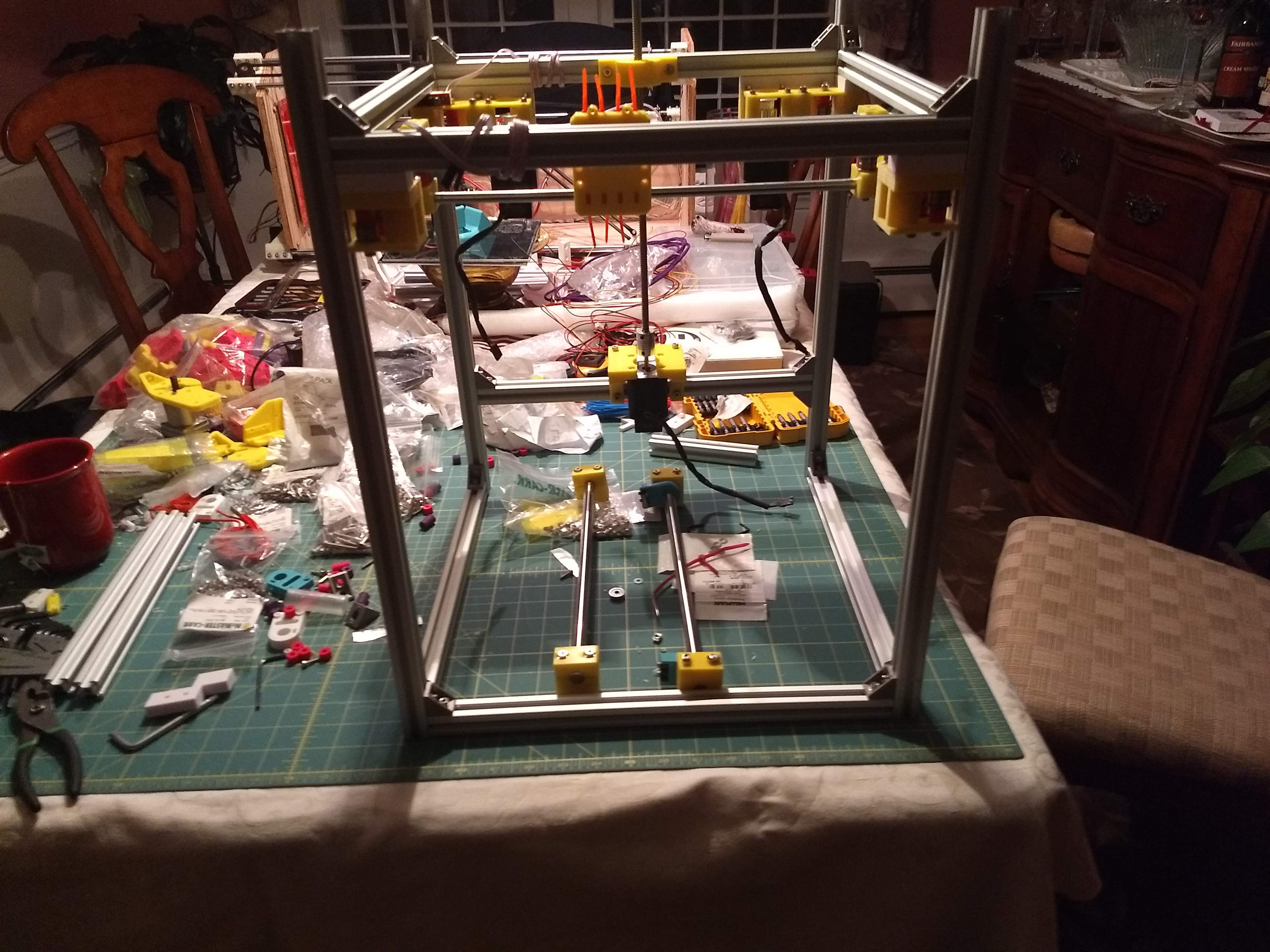
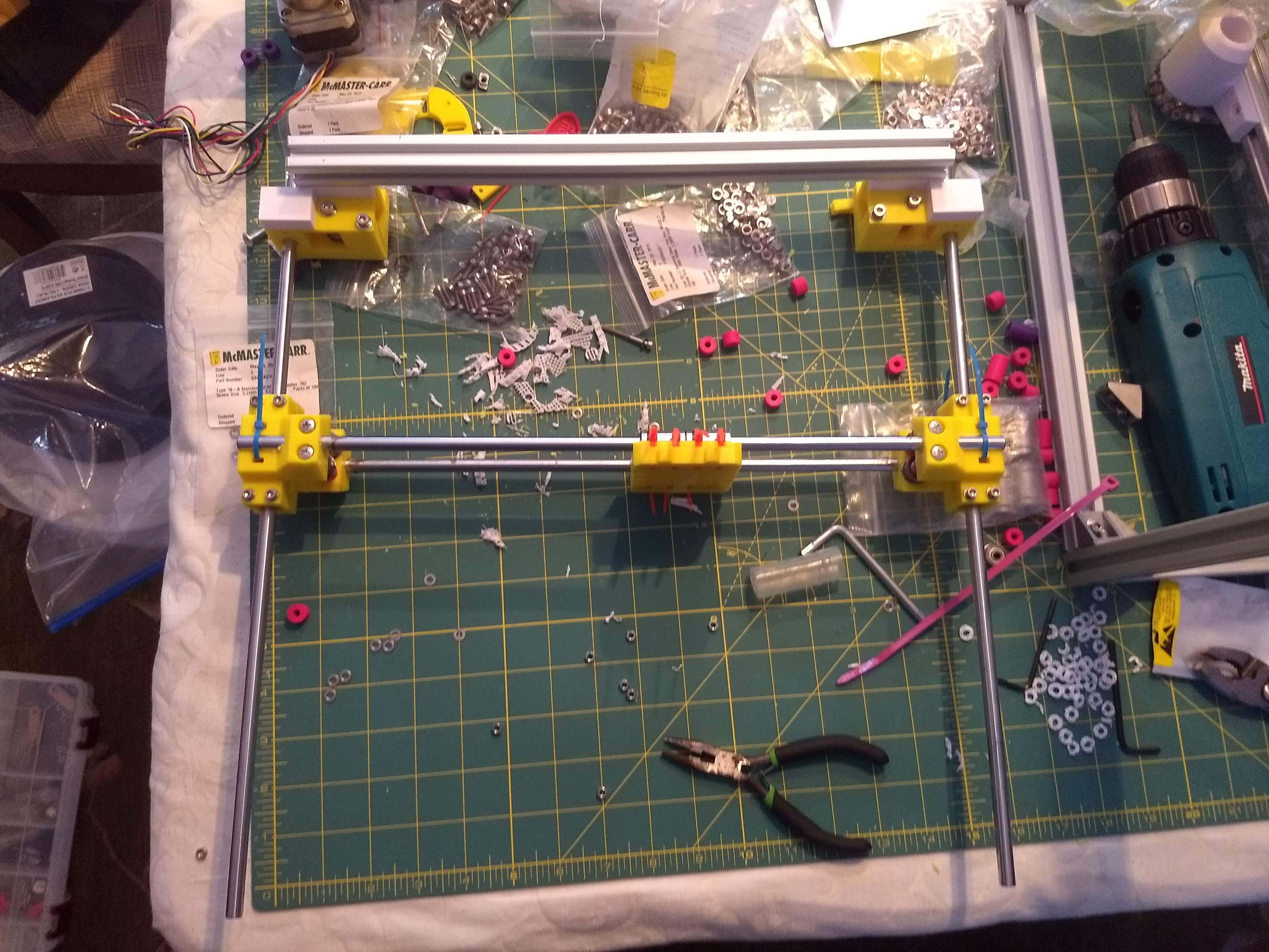
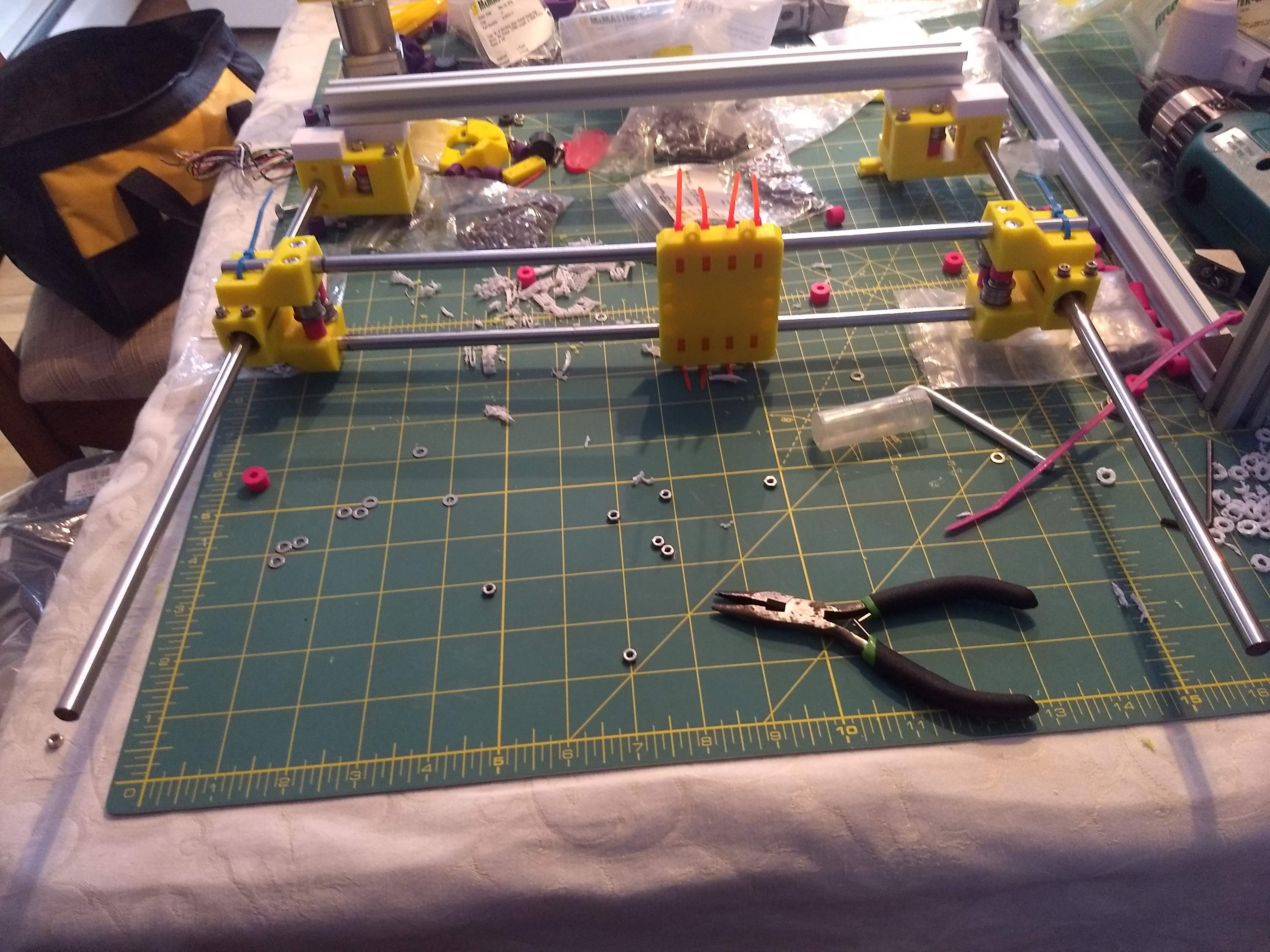
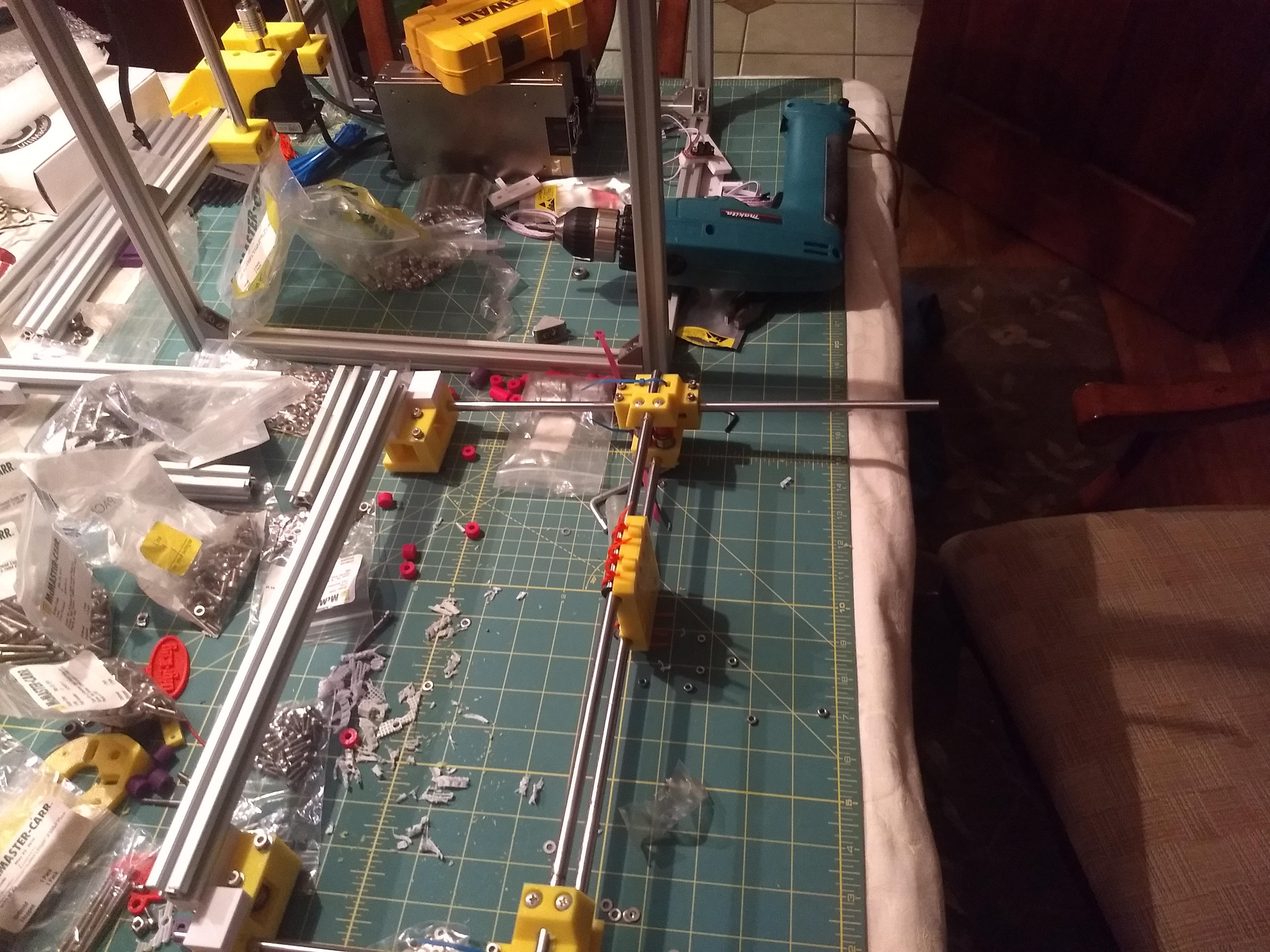
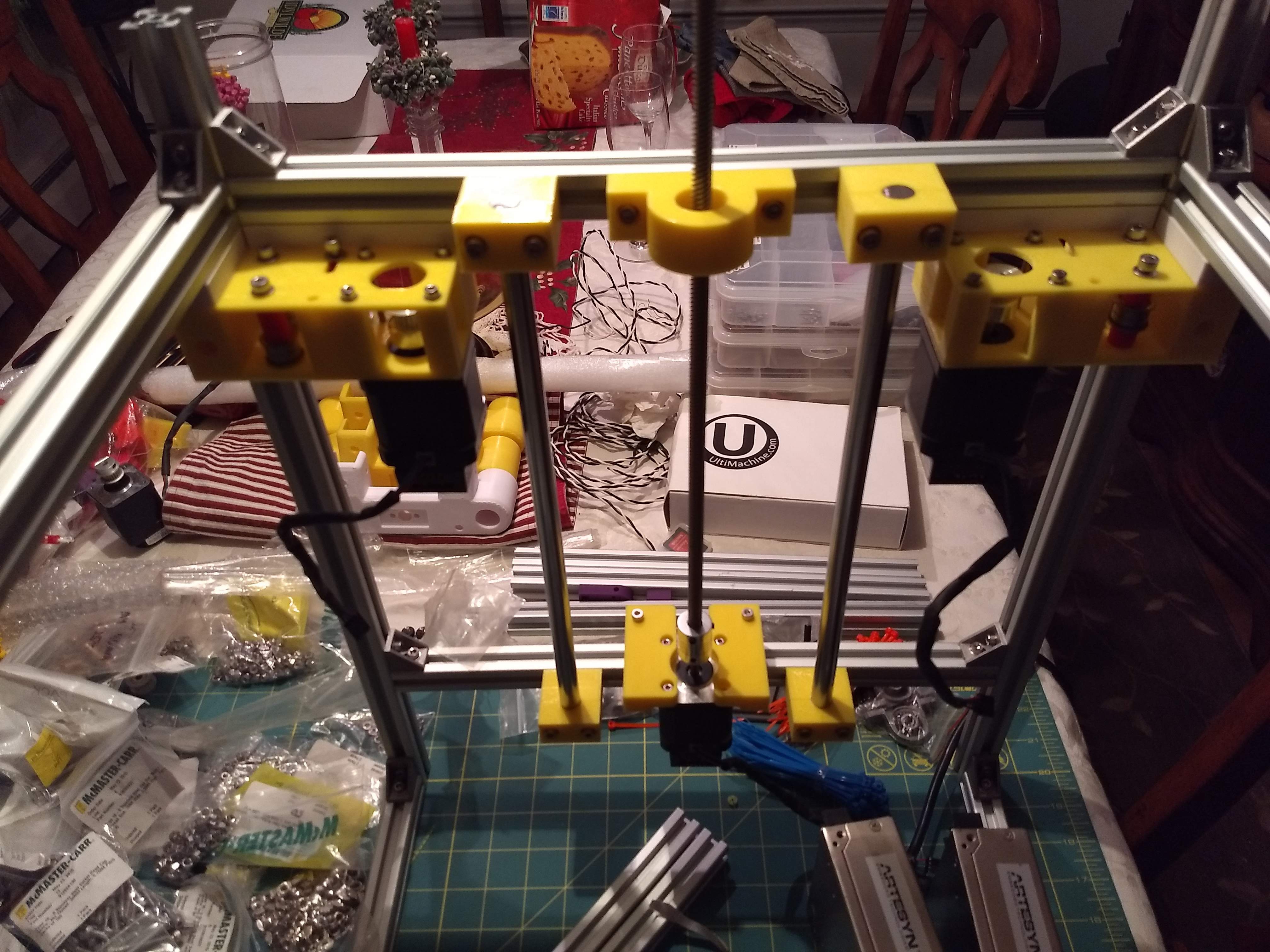
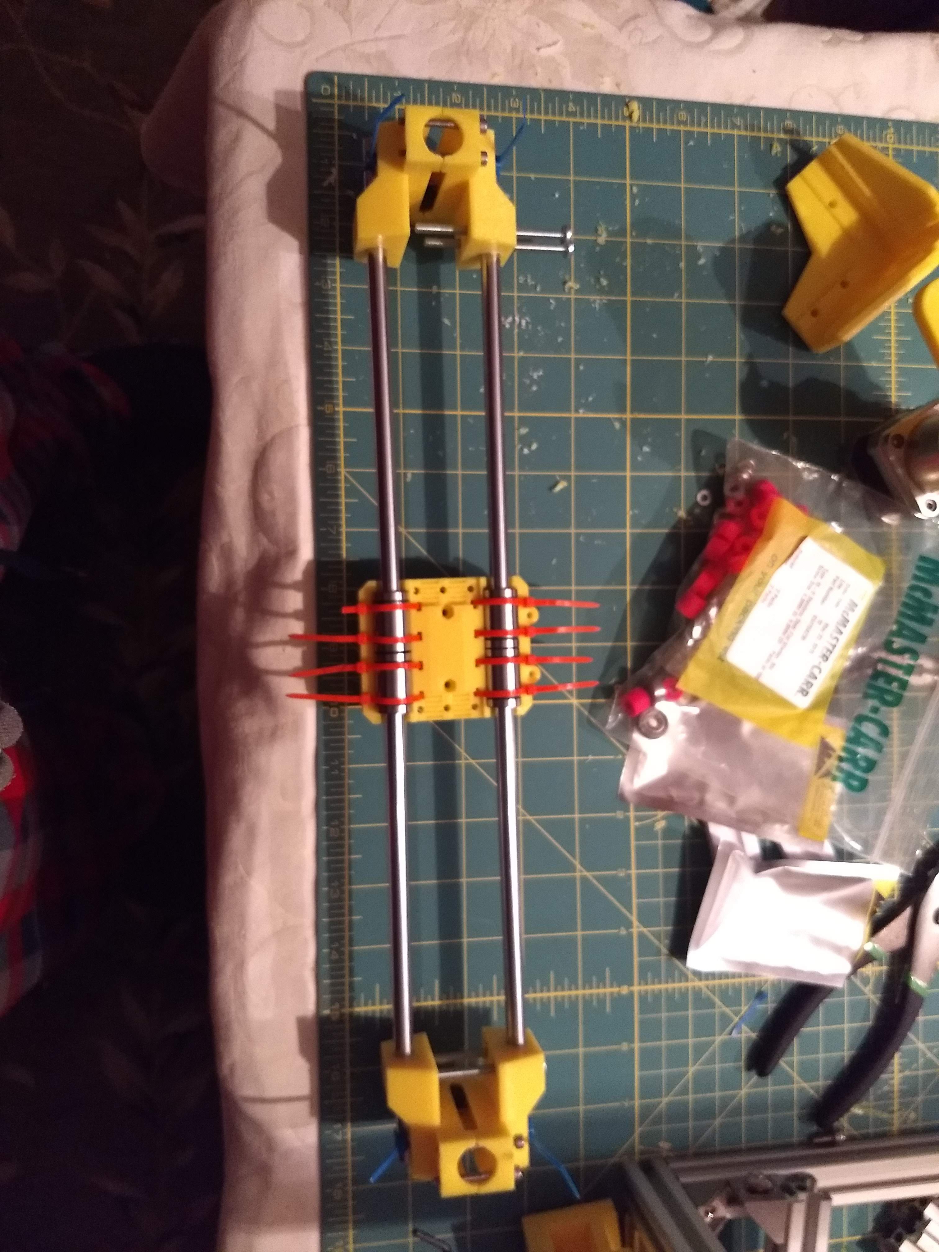
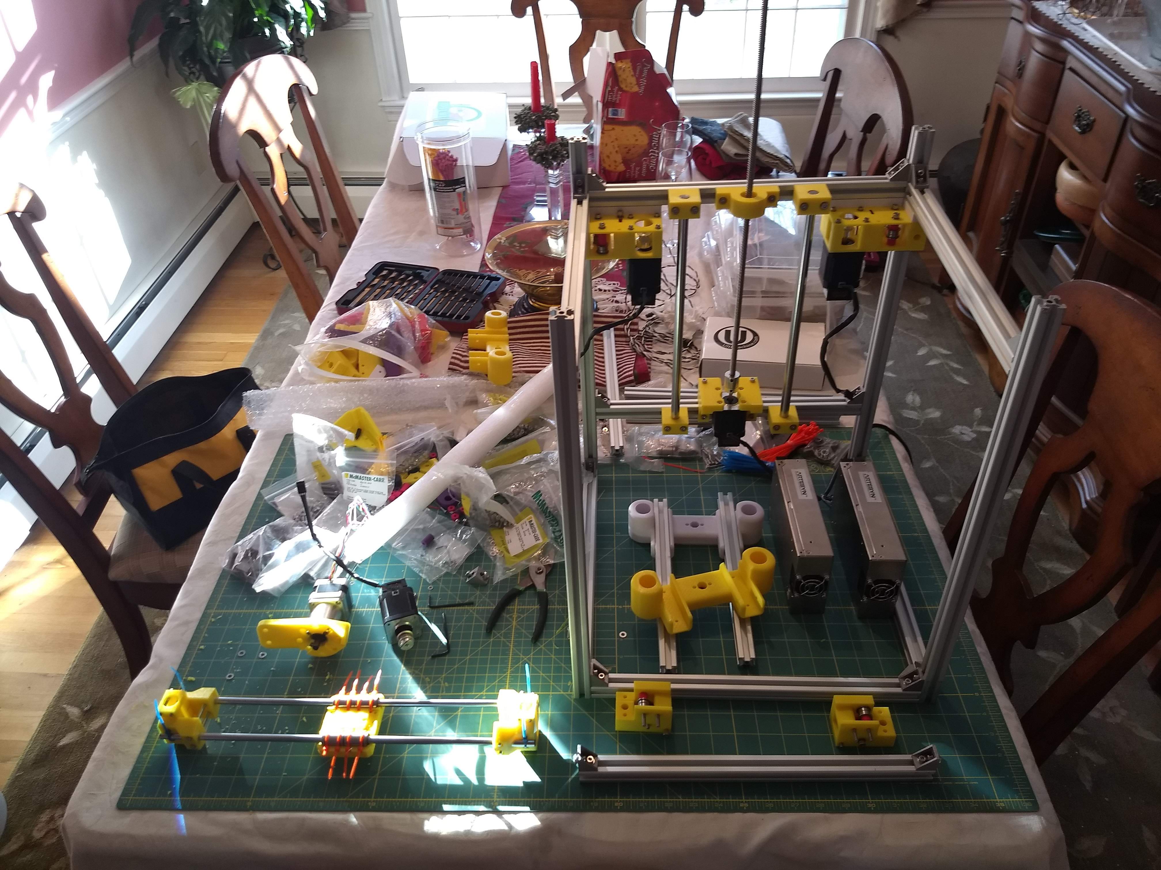
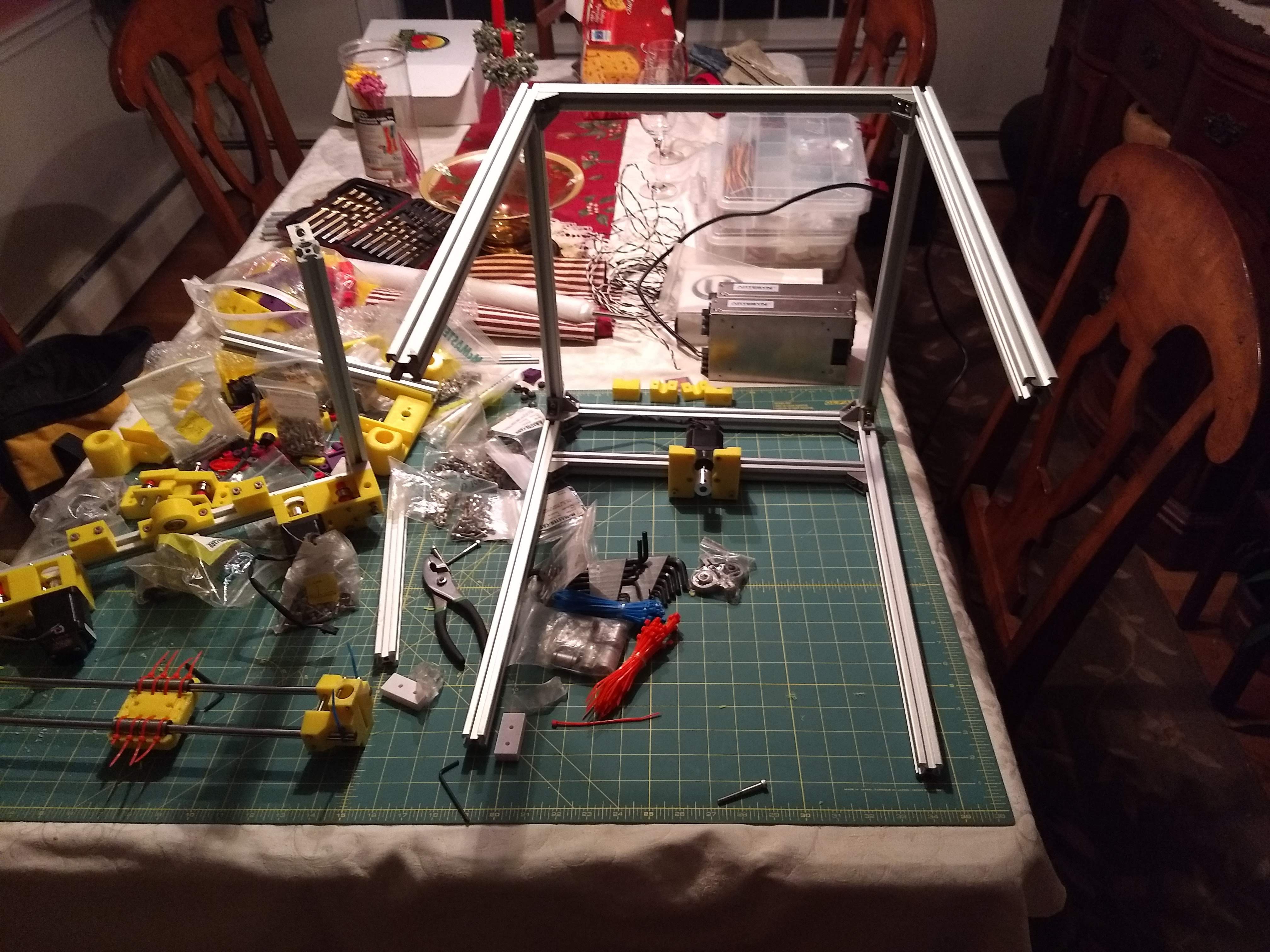
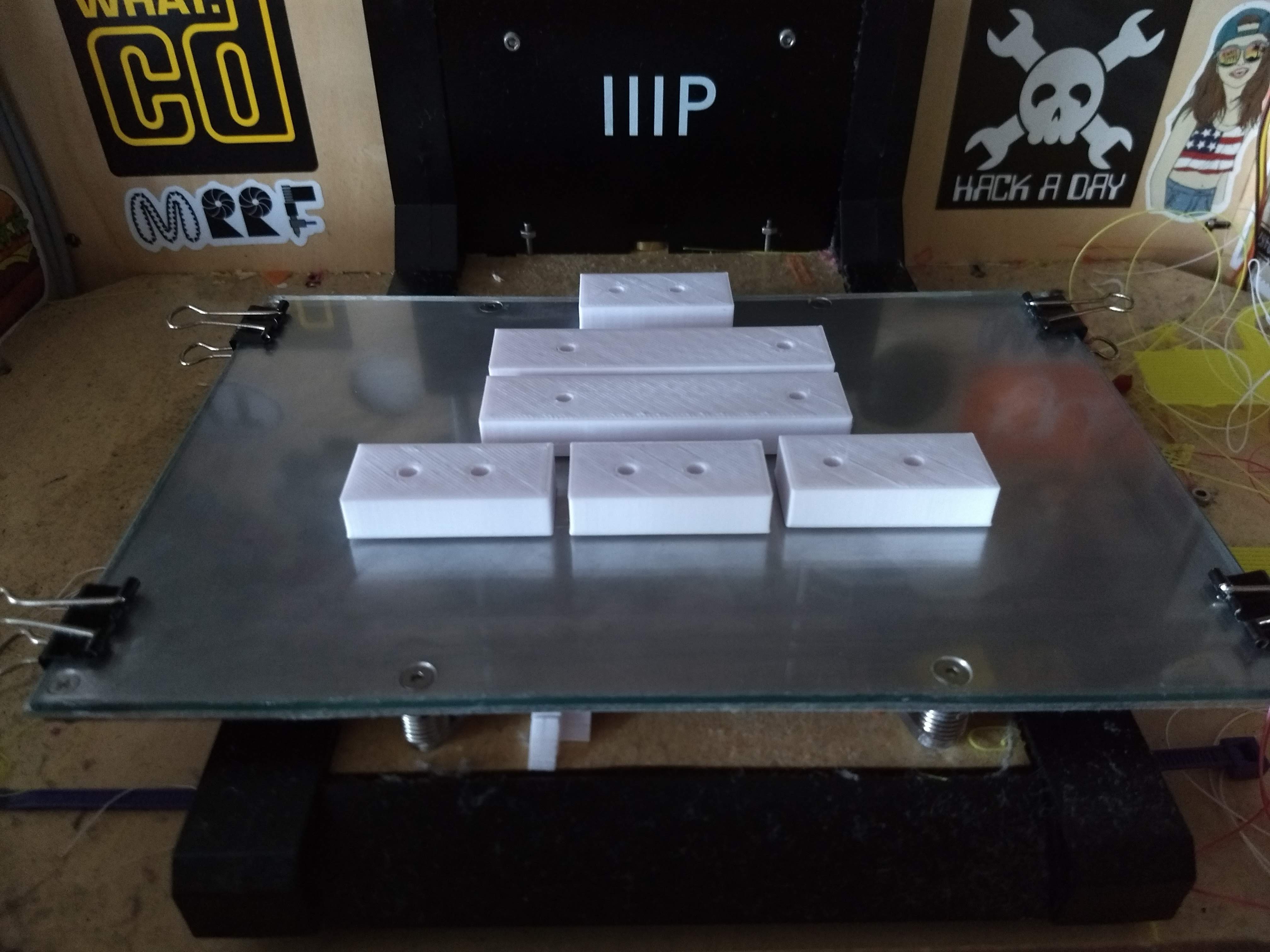
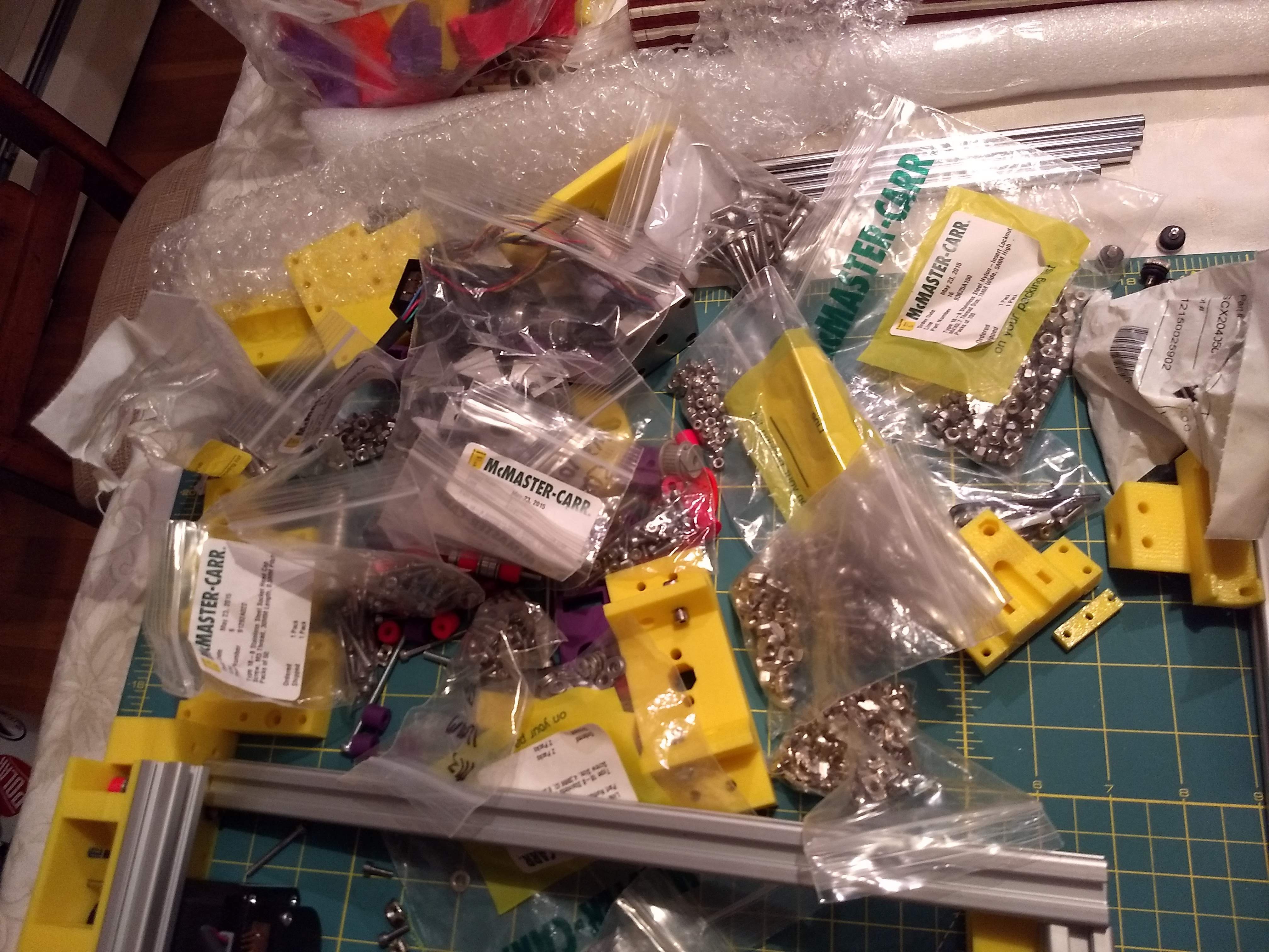
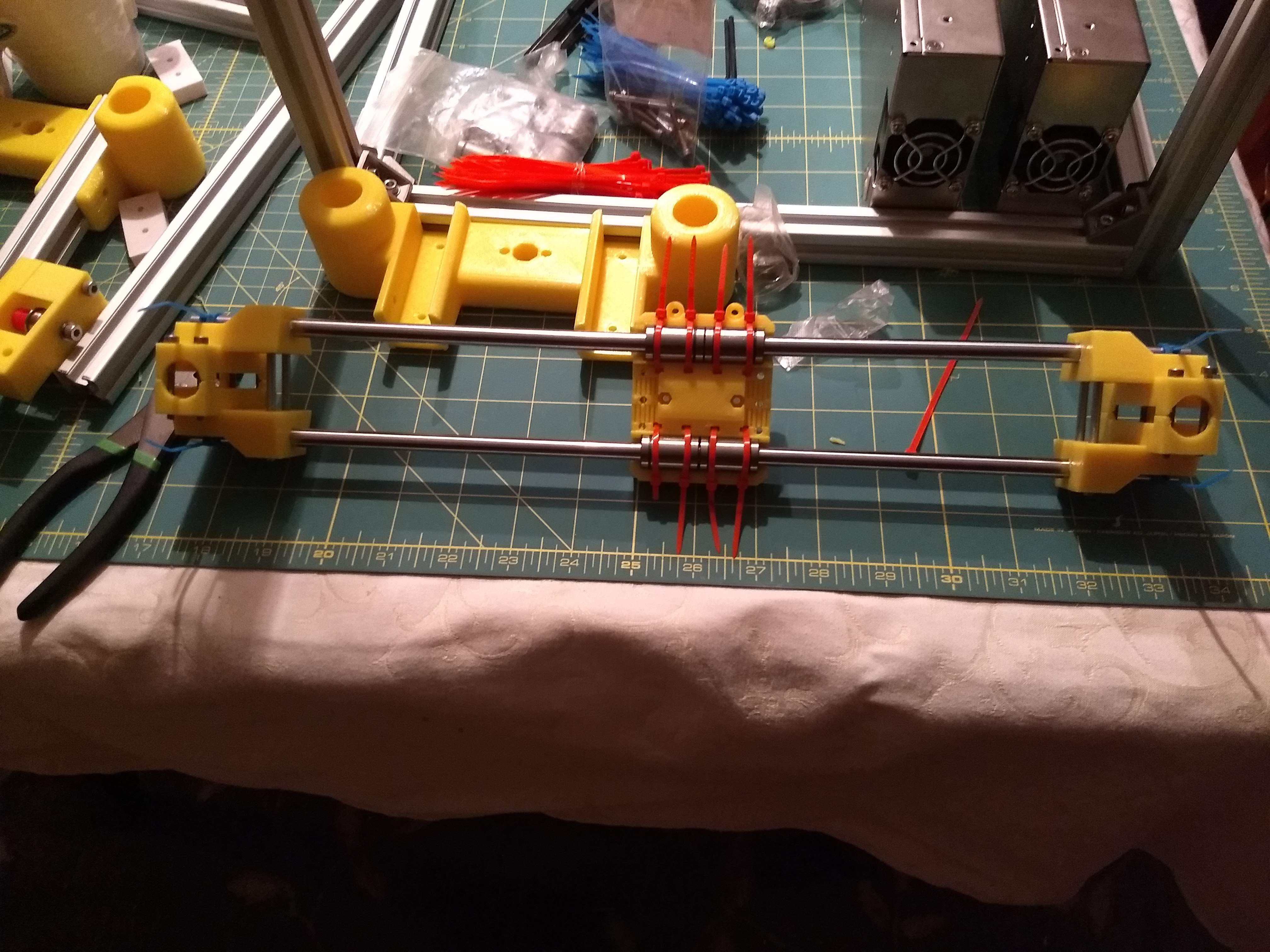
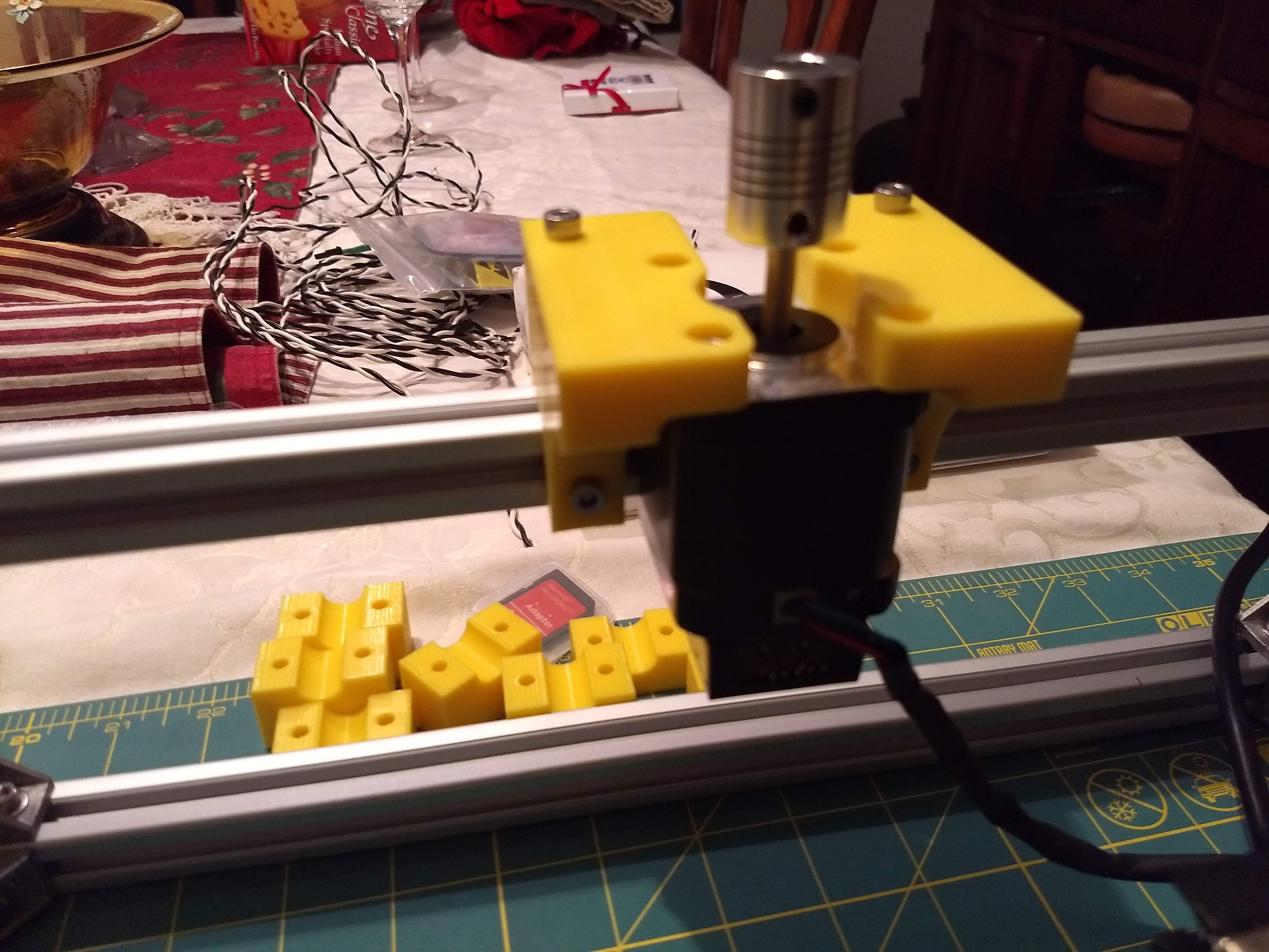
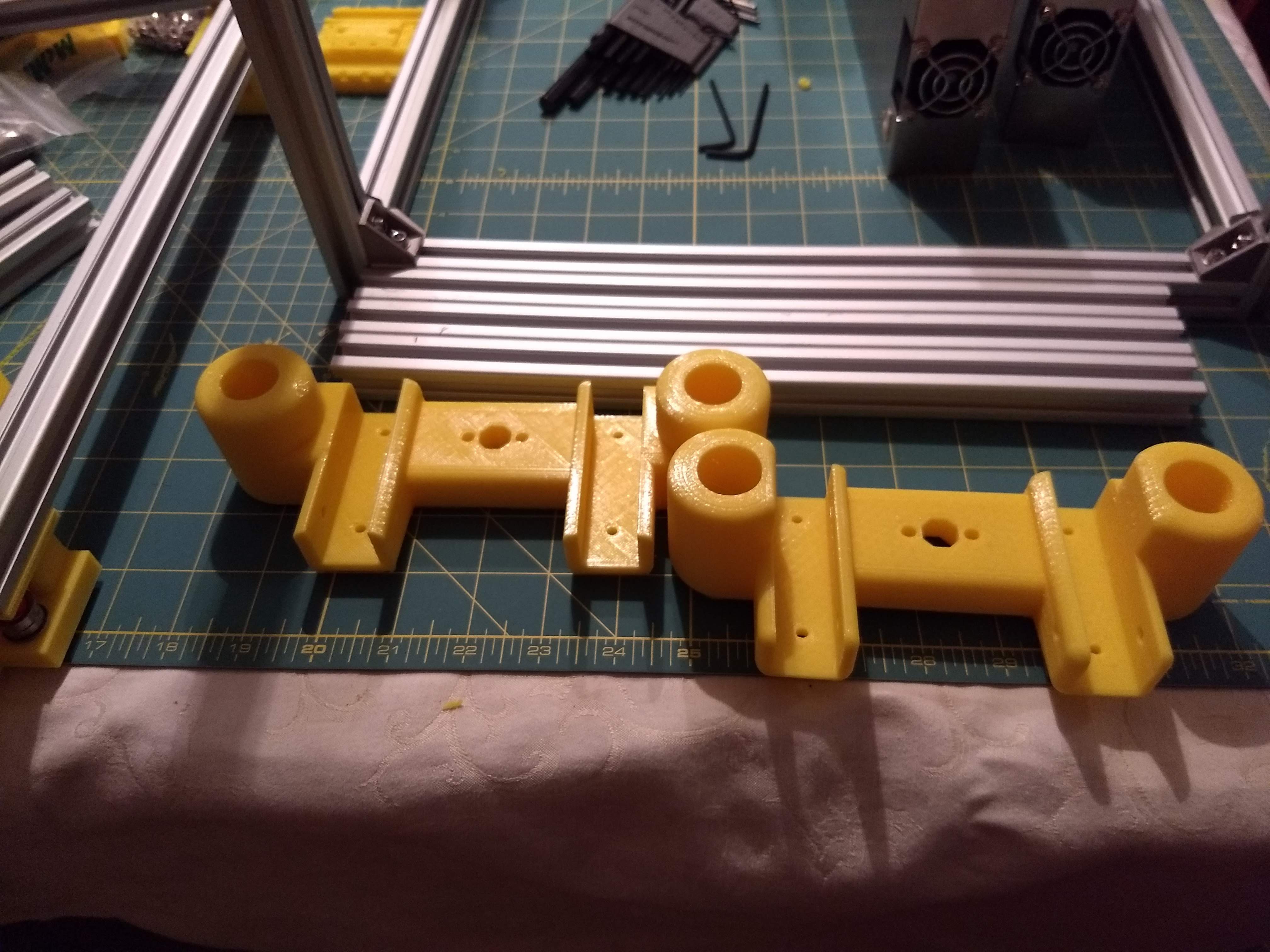
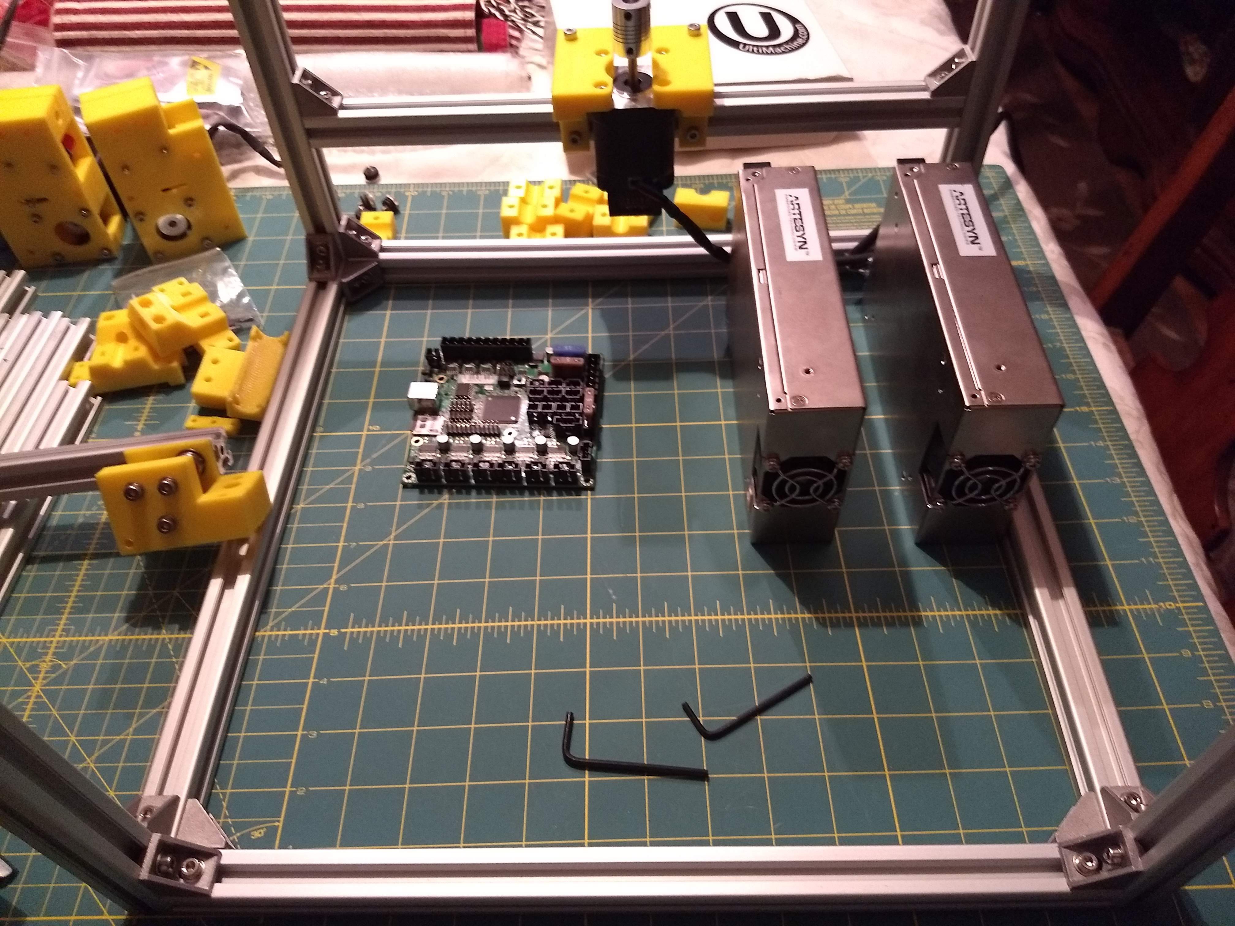
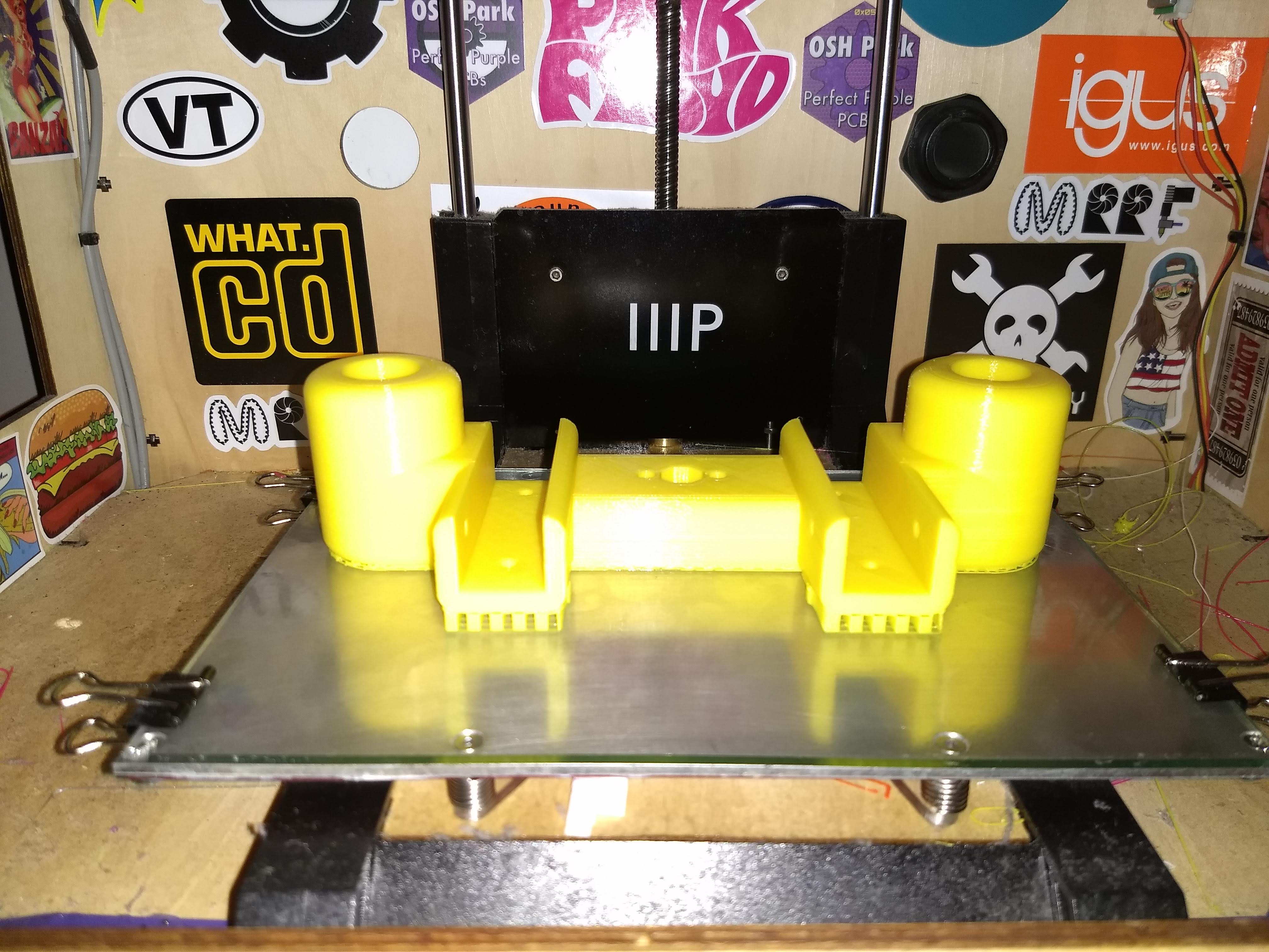
Rods Cut and XY Gantry Installed
01/27/2020 at 08:07 • 0 comments![]()
![]()
![]()
![]()
![]()
![]()
![]()
![]()
![]()
![]()
-
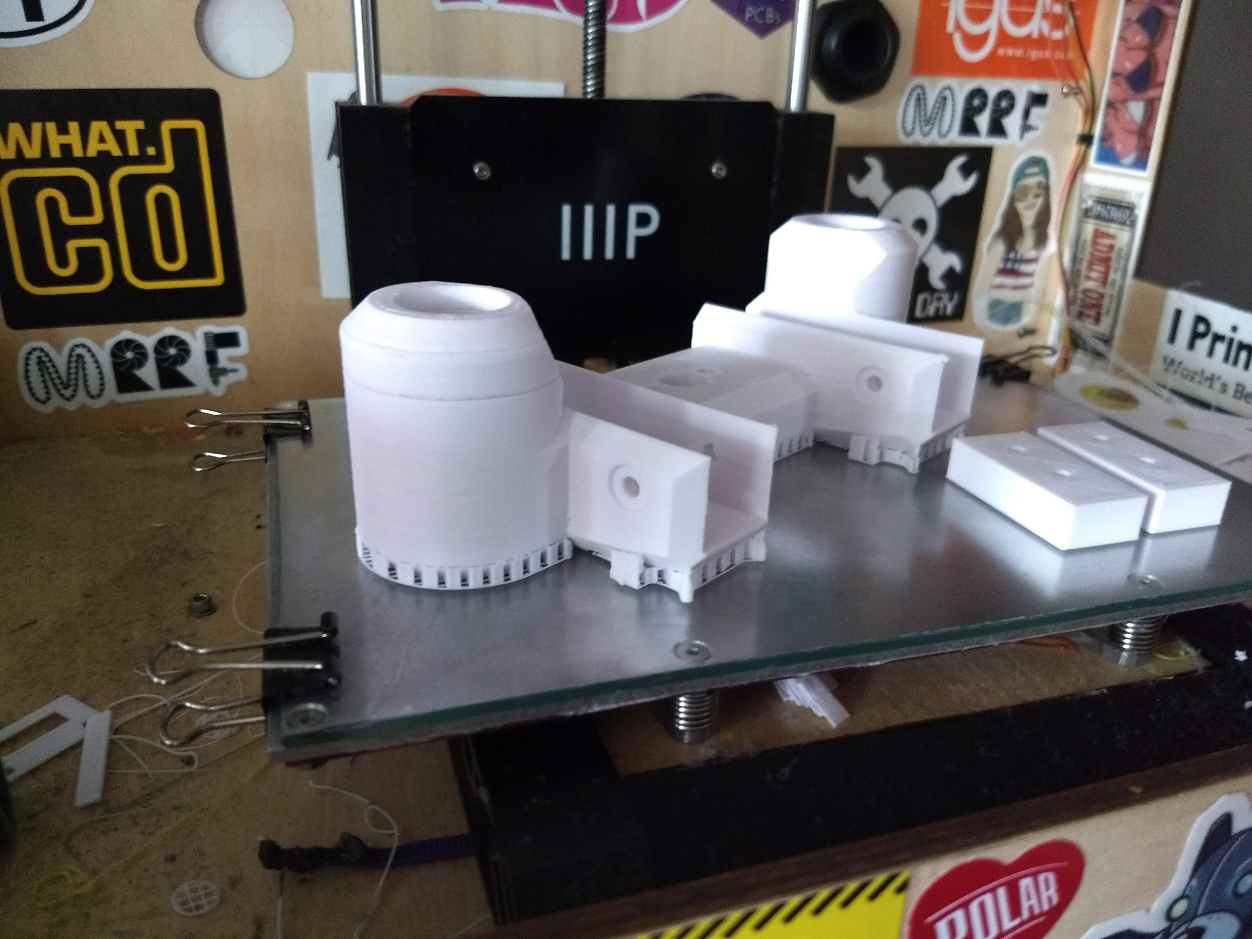
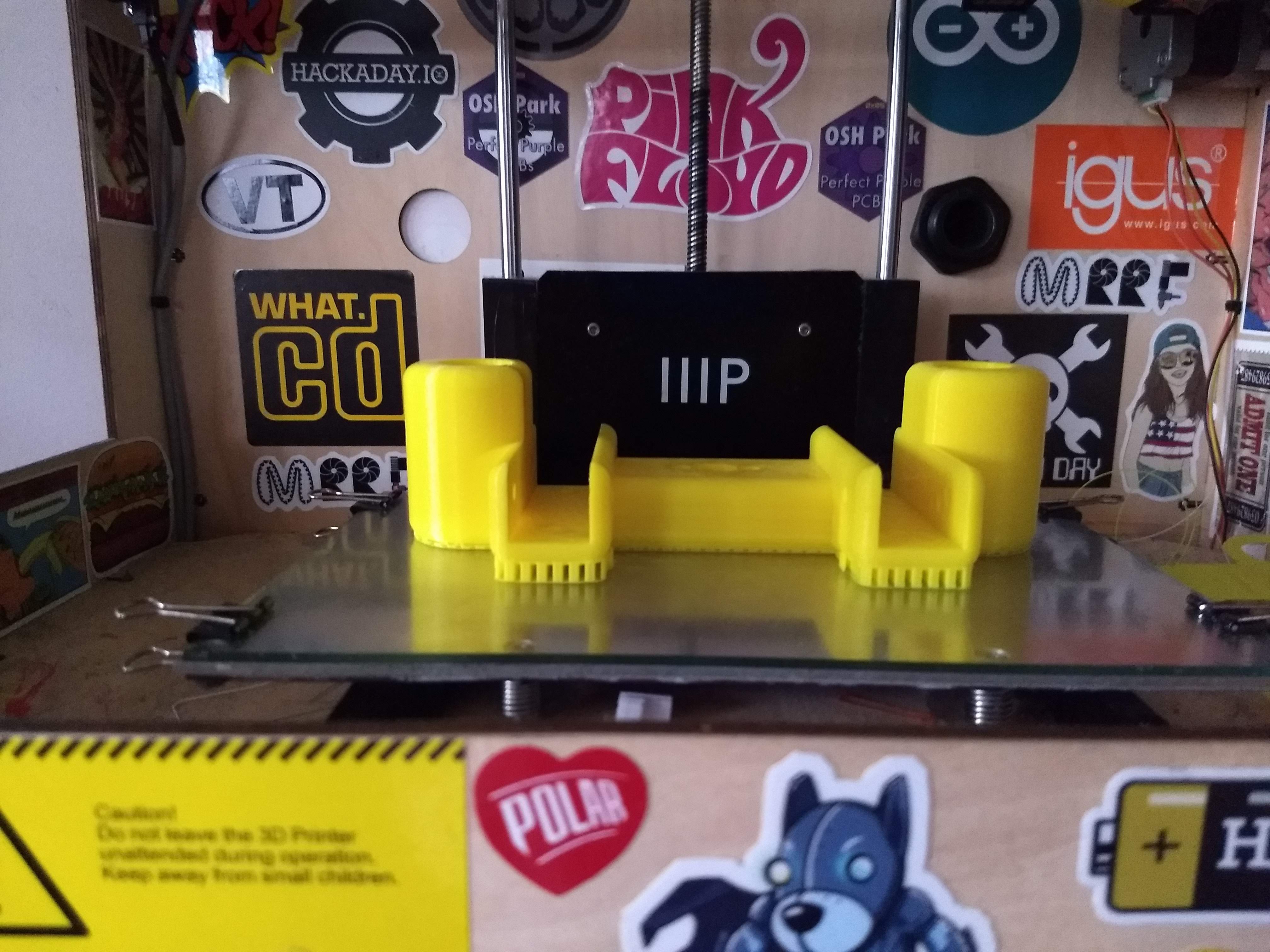
Update: Z Redesign And Reverting to LMUU8
01/23/2020 at 01:47 • 0 commentsRedesigned the Z axis going back to using LMUU8 bearings here is a buttload of pix:
![]()
![]()
![]()
![]()
![]()
![]()
![]()
![]()
![]()
![]()
![]()
![]()
![]()
![]()
![]()
![]()
![]()
![]()
![]()
![]()
![]()
![]()
![]()
![]()
![]()
![]()
![]()
-
CAD Near Complete and New Parts!
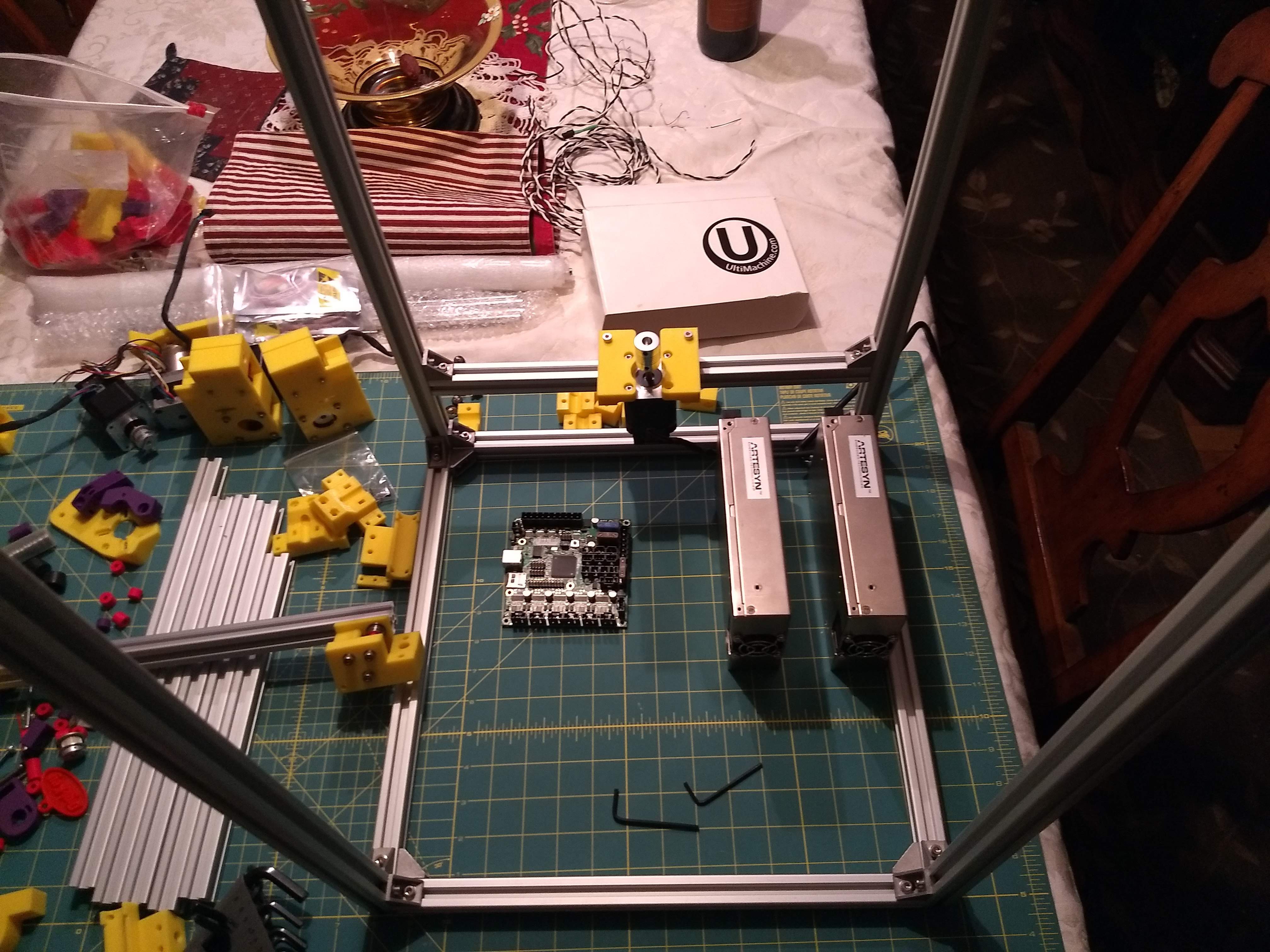
06/12/2016 at 06:20 • 0 commentsRepRap-XY-i2 development resumed a couple weeks ago! I'm happy to say I'm working on this thing again, I've been itching to get it finished for a while. Anyways I have spent the last few weeks printing out all the parts that remain unchanged from Jand's variant. While parts printed I remodeled a few parts of the printer, the Z axis, inner corner brackets, frame corner brackets and the spacer block pieces.
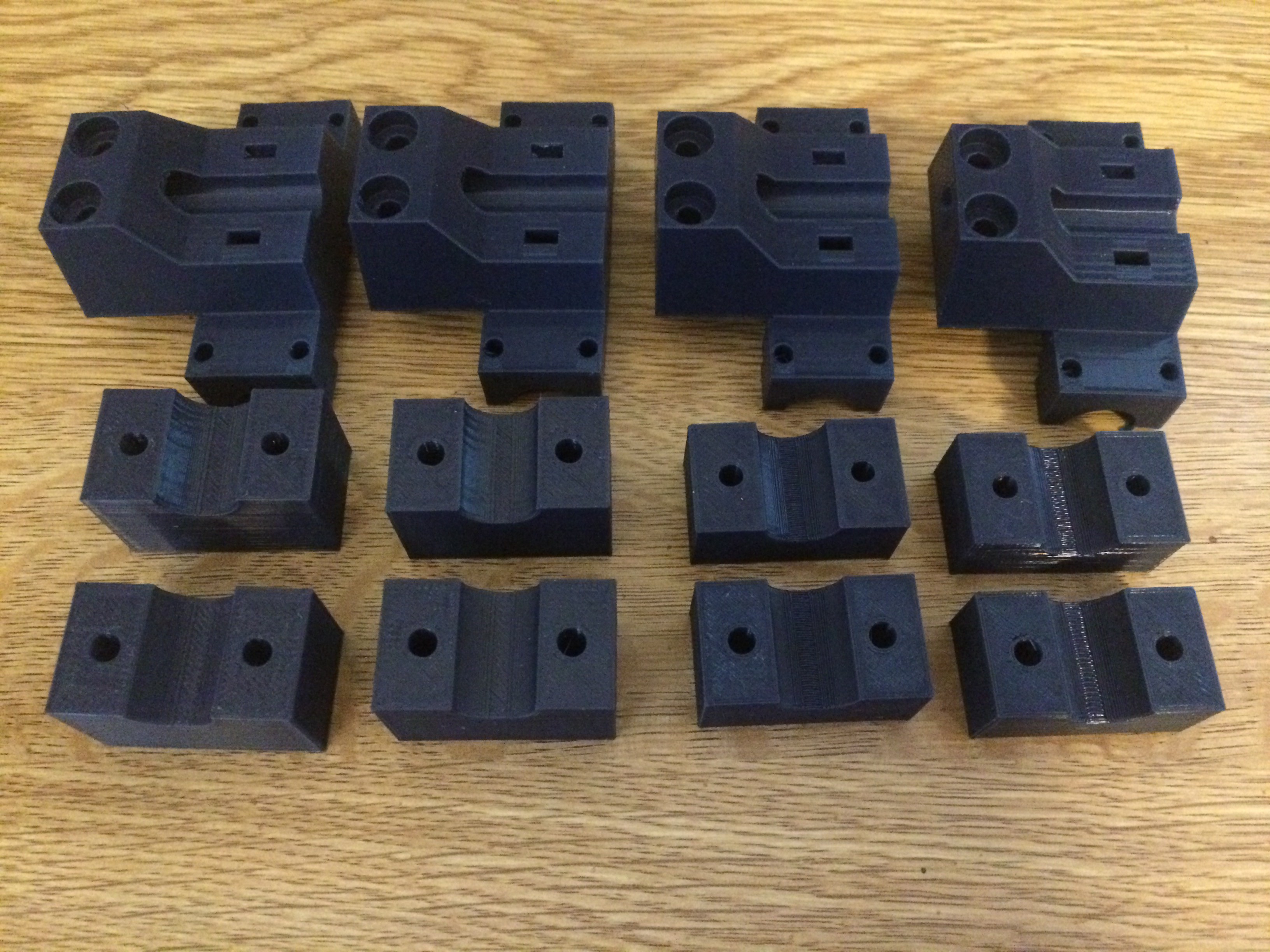
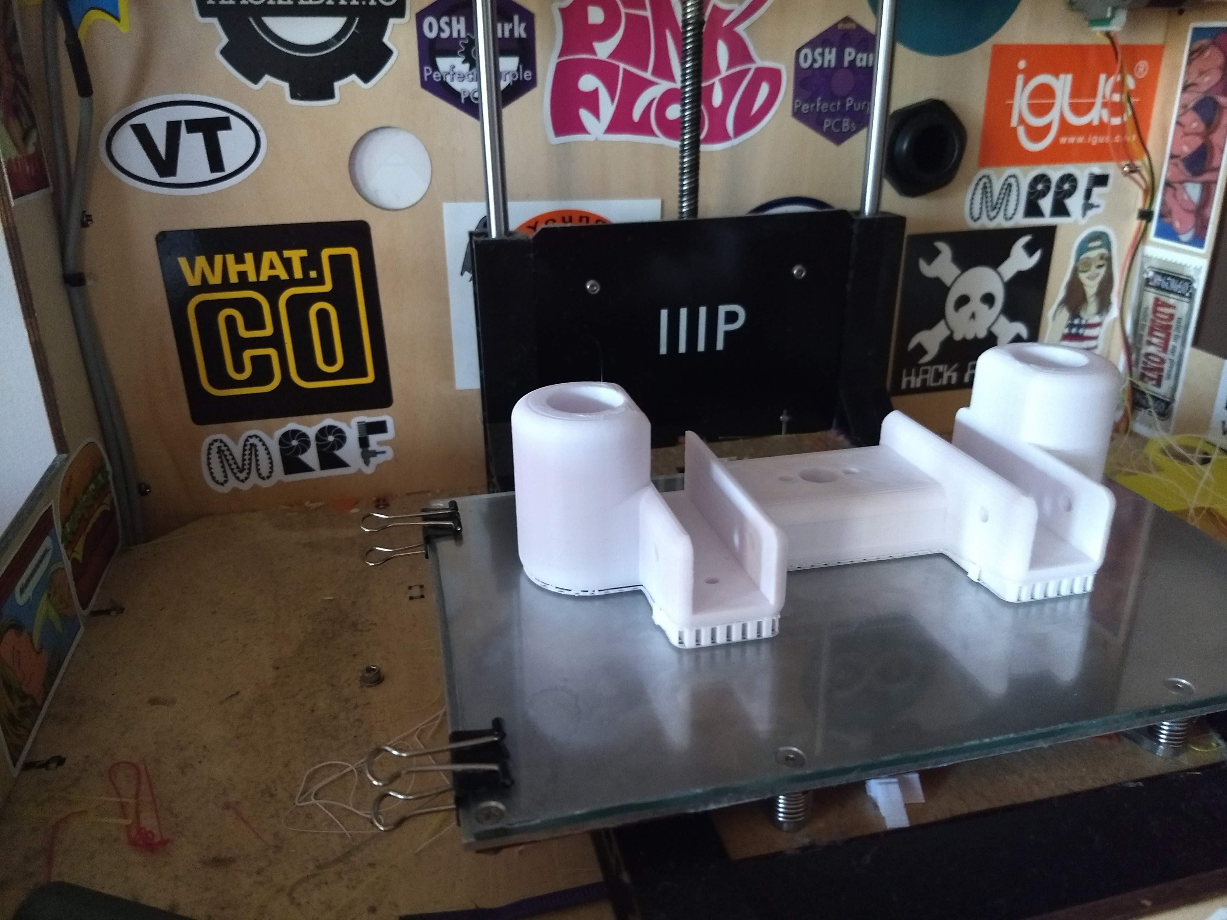
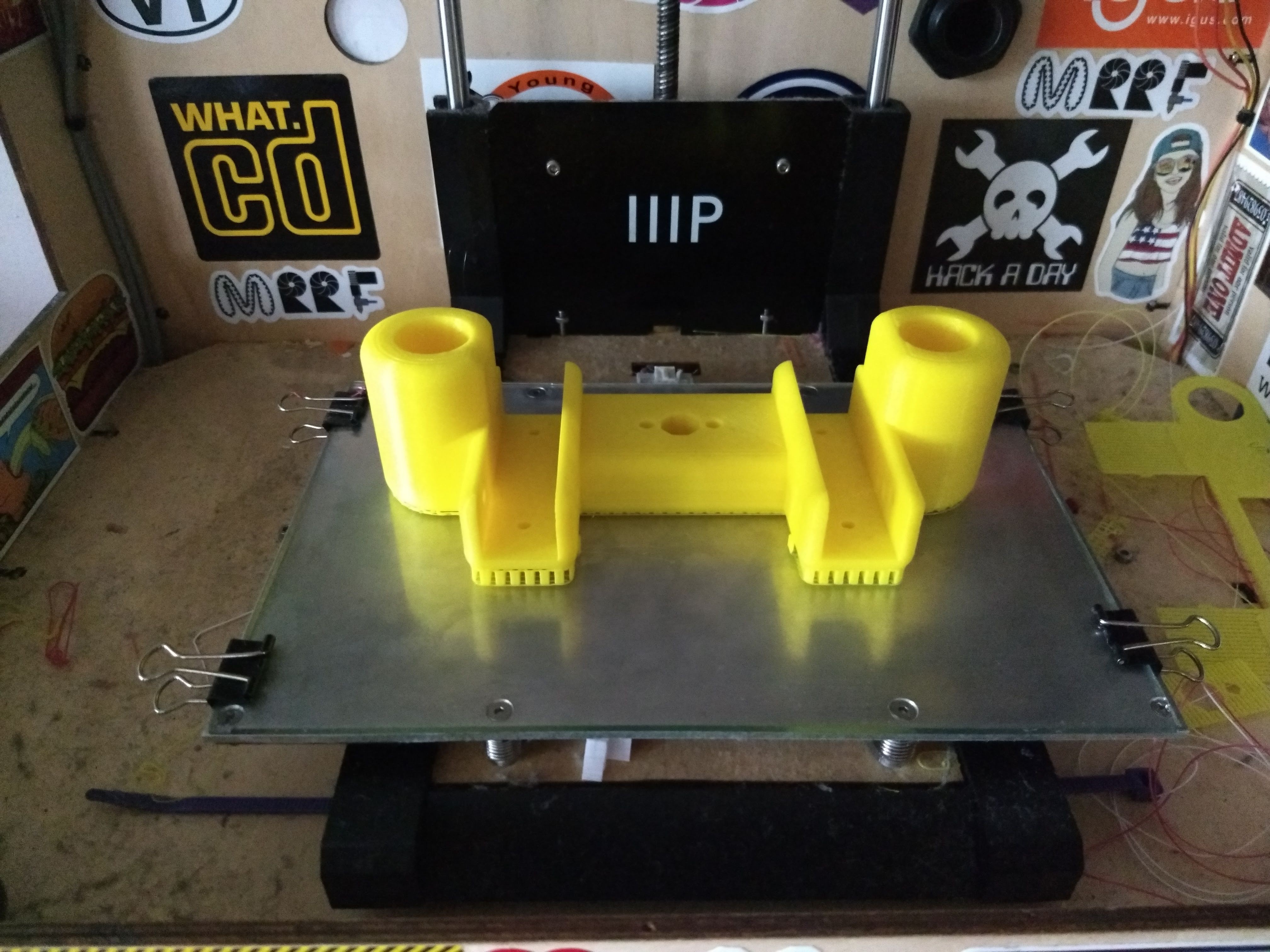
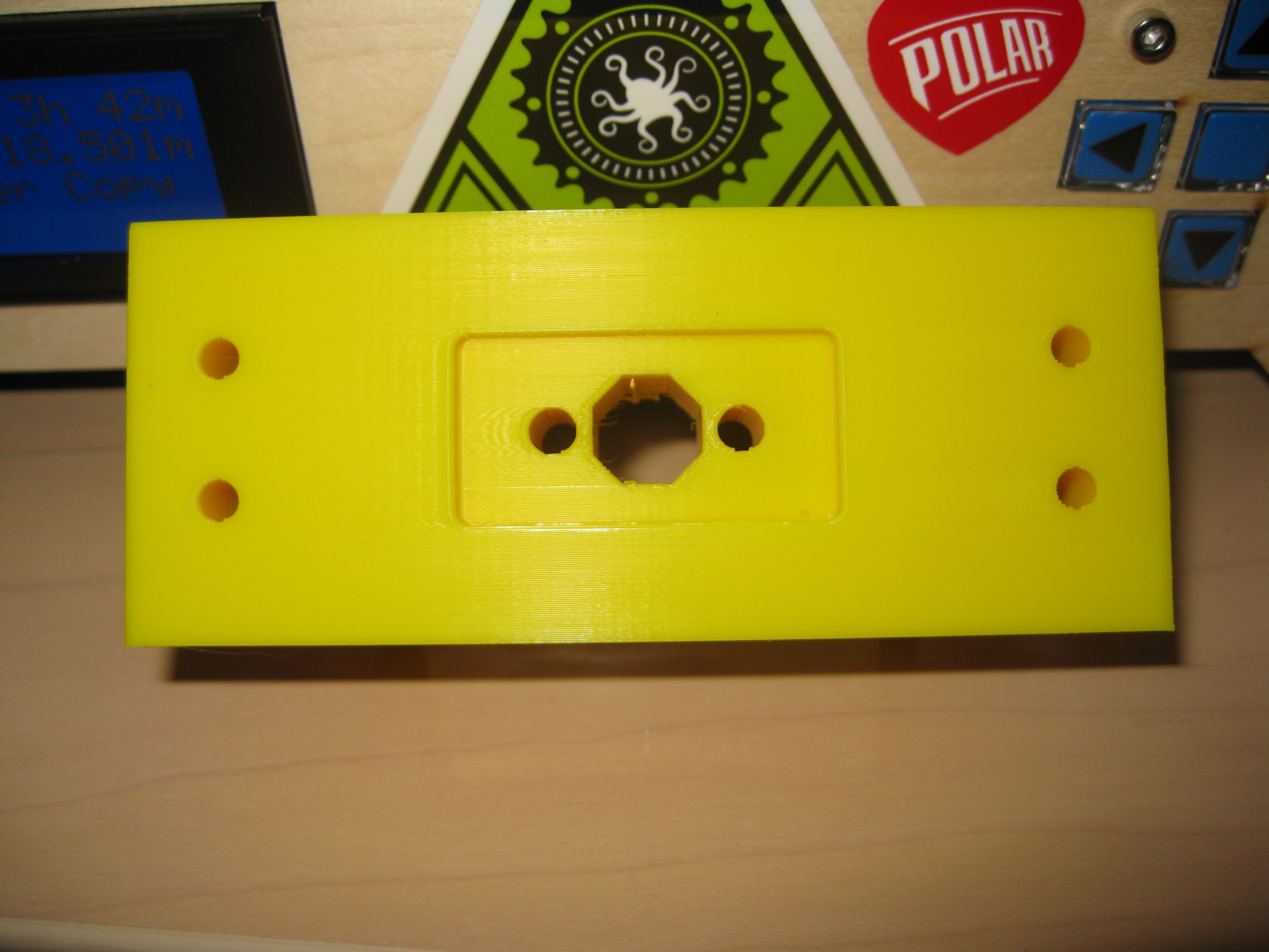
I'll start with the Z axis, originally the Z axis design consisted of many printed parts that clamp together around a M8 nut and clamp onto pieces bolted to the 2020 extrusion. The original design relied entirely on friction and clamping force to hold together the Z axis. I decided this was unacceptable and remodeled it to be 5 printed parts total instead of 9. The redesign is based around a central block type piece:
![]()
This part mounts an openbuilds nutplate for their 8mm leadscrew in the center, the 2020 exstrusion for the Z axis is bolted on the sides. The rest of the Z axis is just the LM12LUU clamp sides that are bolted onto the other sides of the 2020 extrusion:
Overall the Z axis is much more rigid and solid this way, being built around a central piece. The part is also printed to be strong at 30% infill.![]()
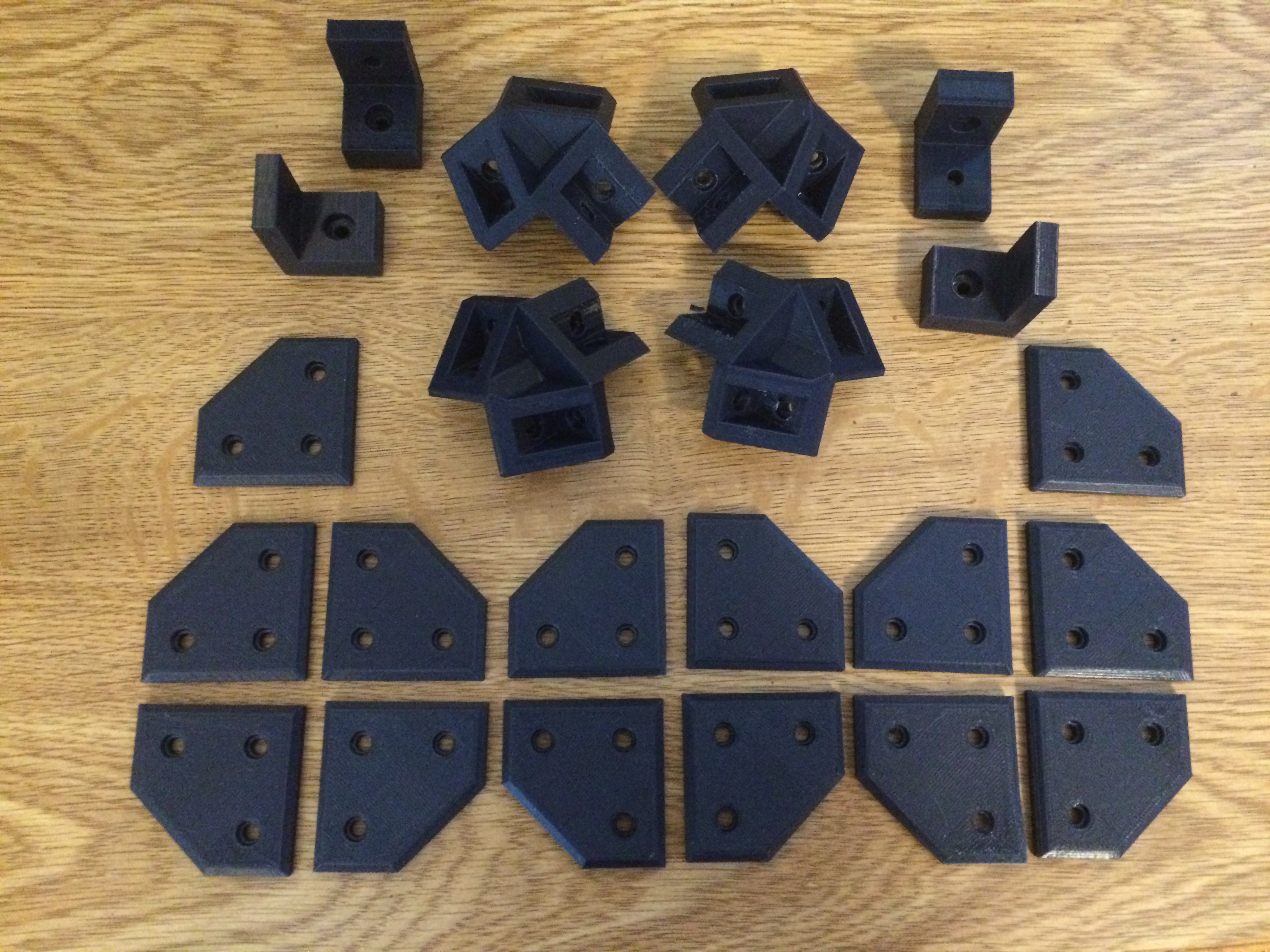
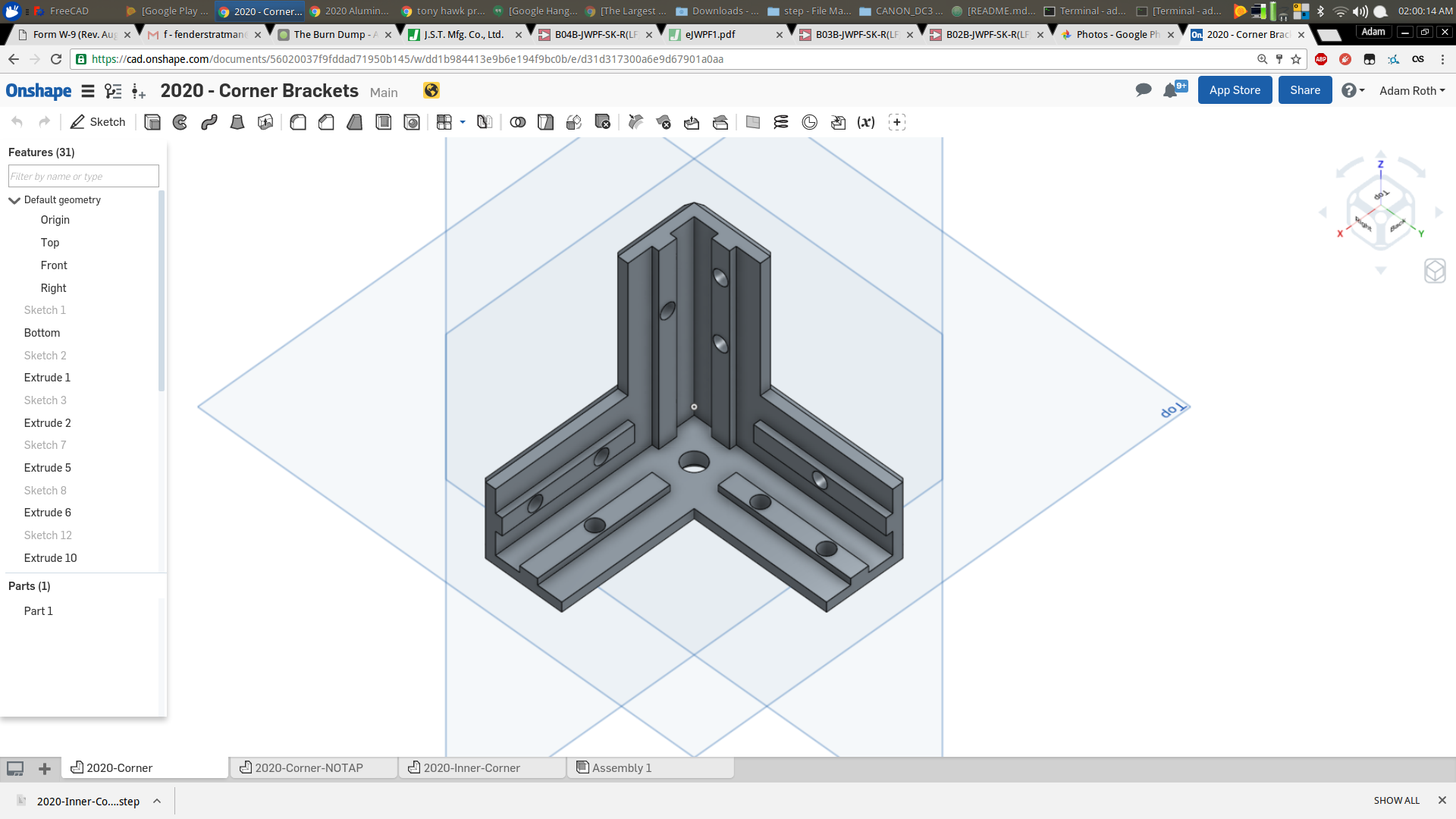
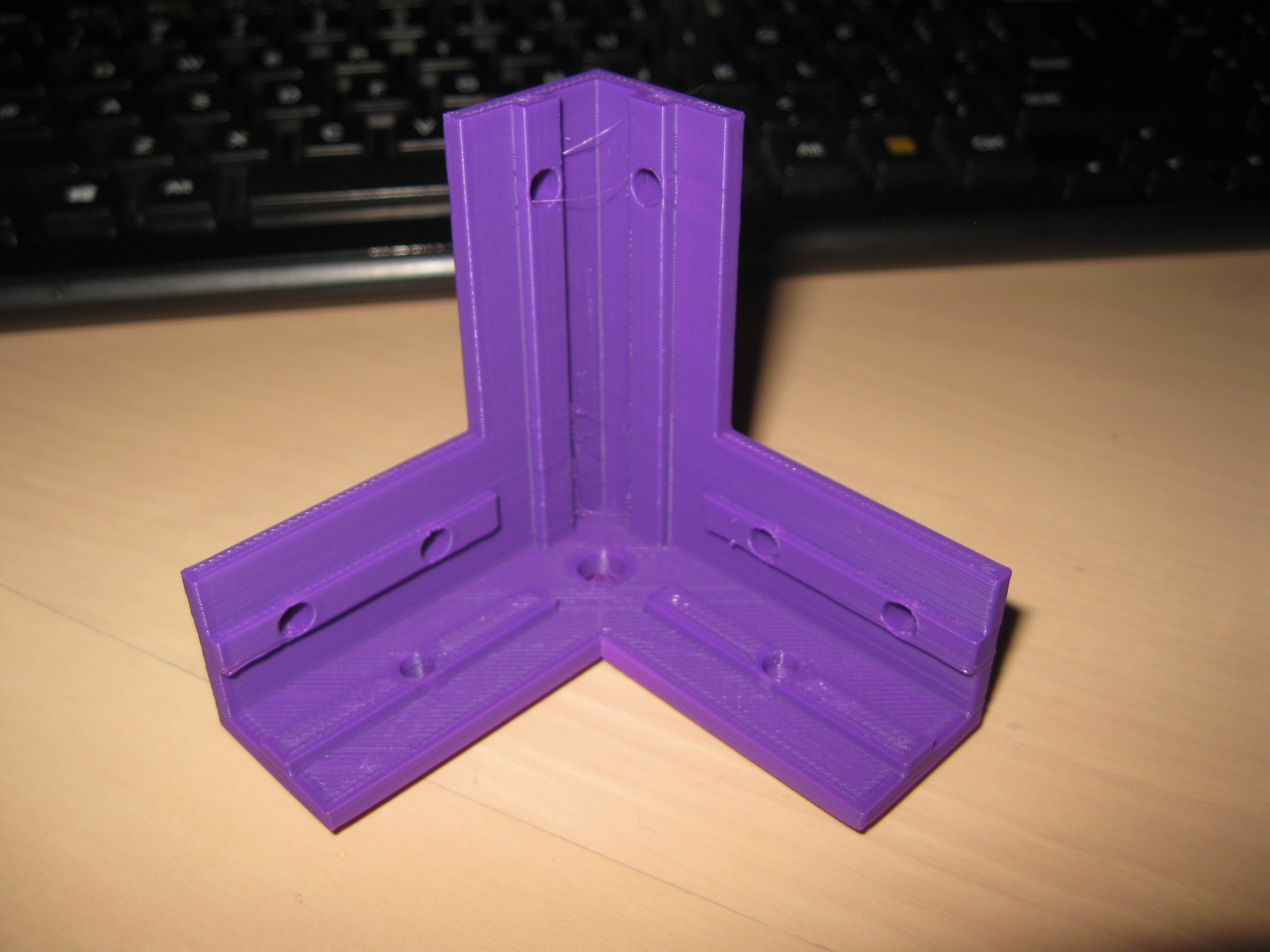
The next big change was a complete redesign of the frame mounting brackets. Over the course of the project I have been toying with quite a few ideas for frame corner parts, I wanted something that was strong but not too long to print. Initially the corners were made out of 3 printed pieces, printed flat on the print bed, this was chosen for its strength properties but suffered from complex assembly. The next iteration of this concept was to design it as one part this went through several iterations of modeling and test assembly before I came up with a combination of strength/optimal print time. After modeling a few different designs I settled on this :
Test print before hole revision:![]()
![]() Test Print specs: PLA 40% infill 1.2mm perimeters, 0.2mm layer height.
Test Print specs: PLA 40% infill 1.2mm perimeters, 0.2mm layer height.I really like how this corner came out, its quite sturdy printed out of PLA, I didn't expect it to be so strong. The corner features, internal extrusions to guide the aluminum pieces, I'm playing with tolerances as I go, I might be able to print it for a snug locking fit with the aluminum. So initially these are meant to guide and aid in square assembly but I hope to get a dimension for a tight locking fit. The corner also contacts each aluminum piece at 3 points in a triangular pattern. The screw holes are meant for M4s except the end being meant for M6 for tapping the hole int he 2020 extrusion.
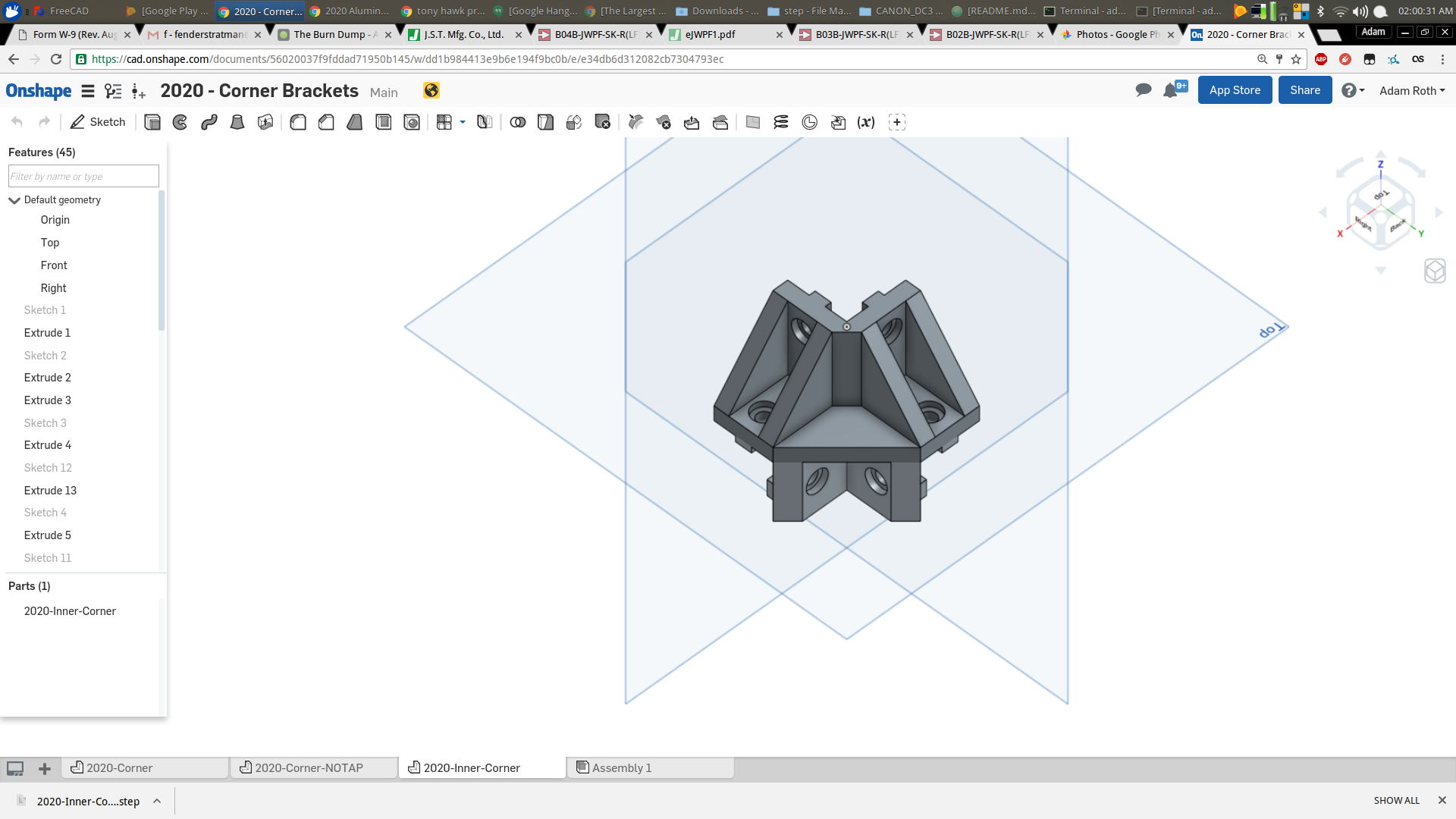
Next part was the inner corner, the initial inner corner pieces were difficult to print, had very poorly defined geometry, screw holes too close, and screw holes not dimensioned optimally for printing. The part is almost entirely the same but remodeled with correct screw hole dimension, correct screw spacing, and the ability to be printed flat without support material. After about 20 minutes of modeling in OnShape I came up with this:
The part is basically the same with better defined geometry resulting in a much neater solid without any weird extrusions left over. The part is flipped on the triangular side (seen in the picture) it prints without support material, and definitely needs a cooling fan to print nicely. Other new additions over the original part include extrusions that fit into the 2020 extrusion slots like the corner, this is to aid in assembly and like the corner eventually will be modified to have a very tight fit.![]()
Lastly I modified the spacer blocks for the motor blocks and idler blocks, all that was changed were the screw holes were spaced apart and resized for better printing tolerance. Thats all for now, stay tuned for further updates! -
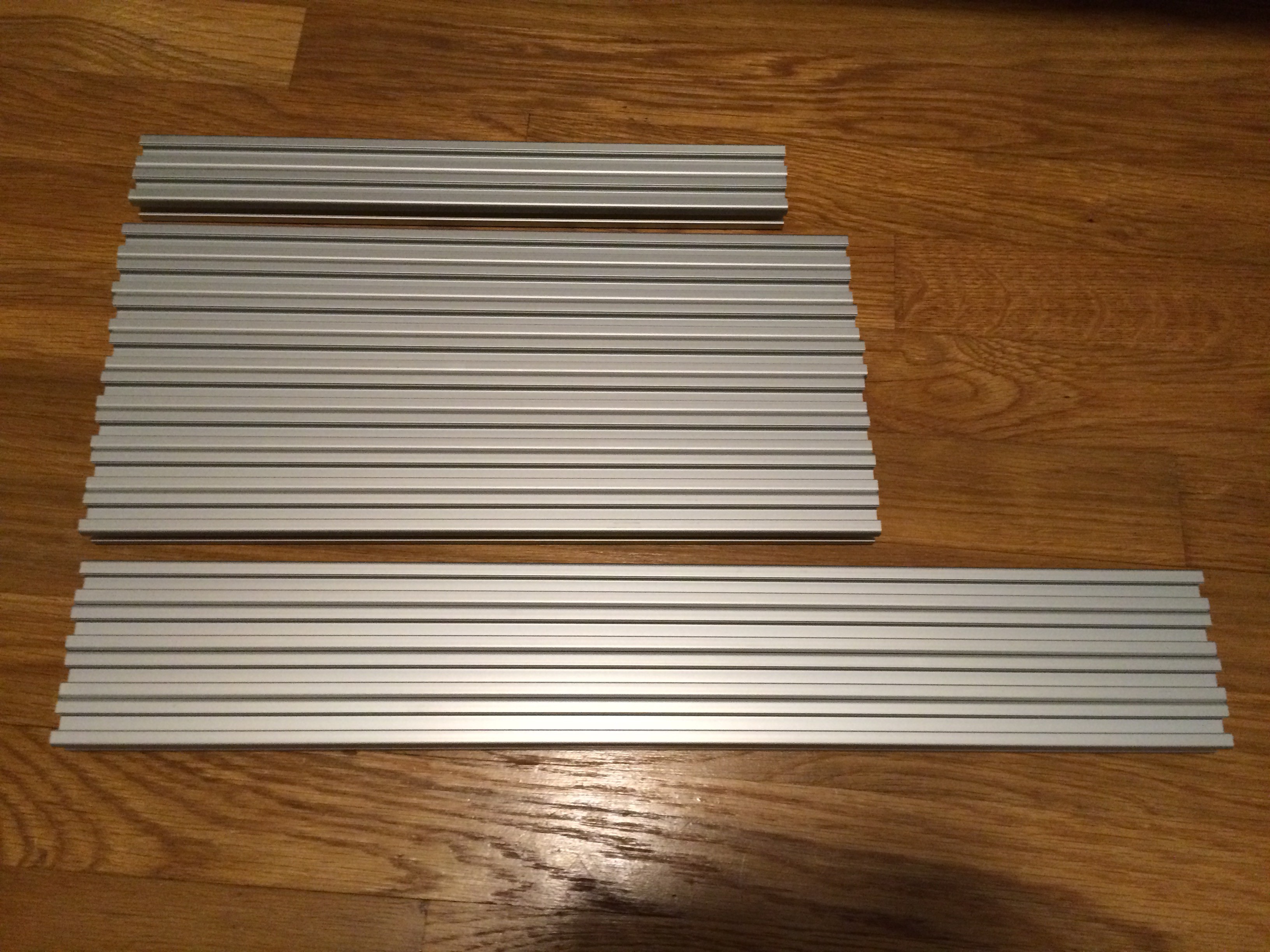
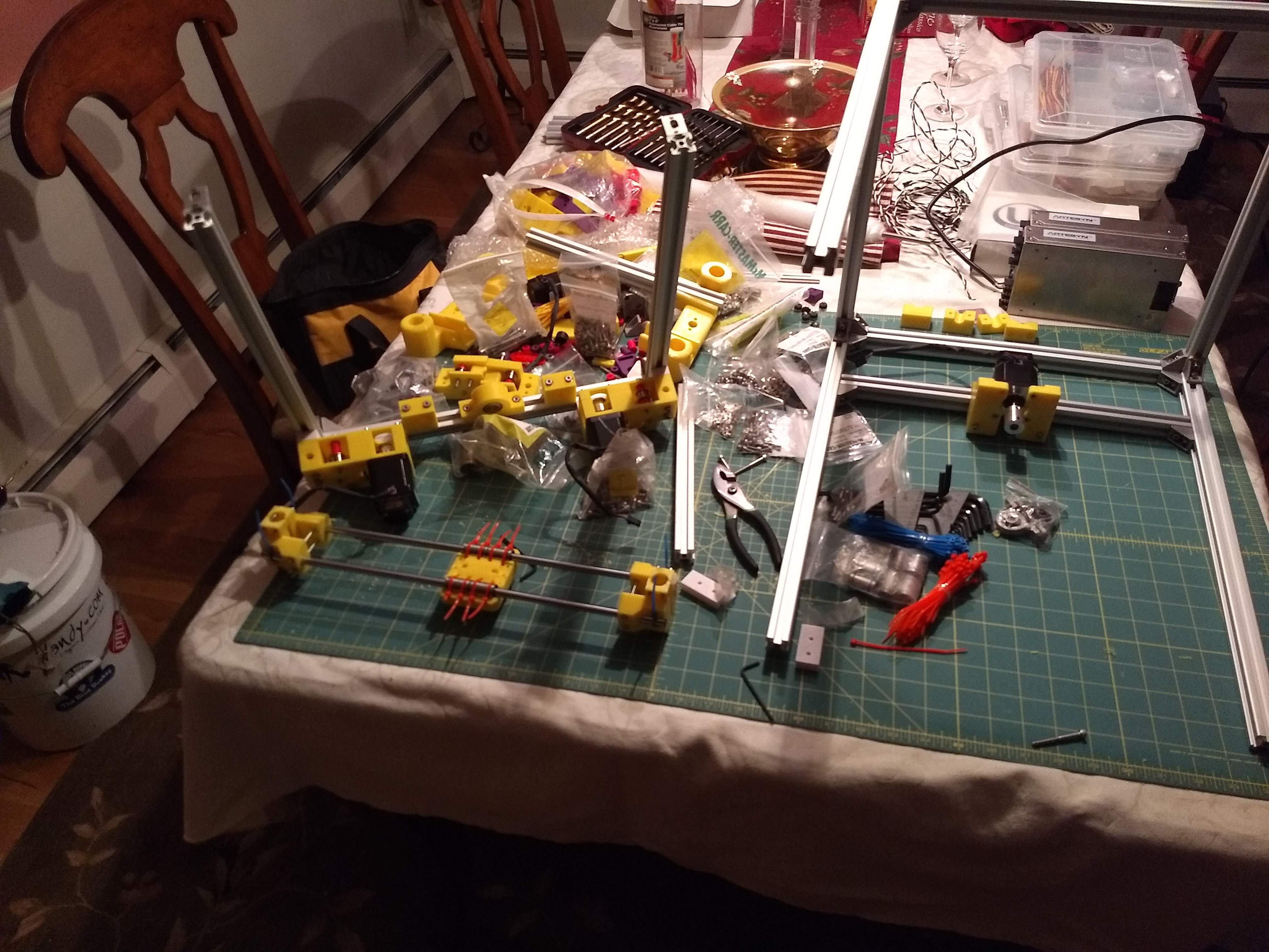
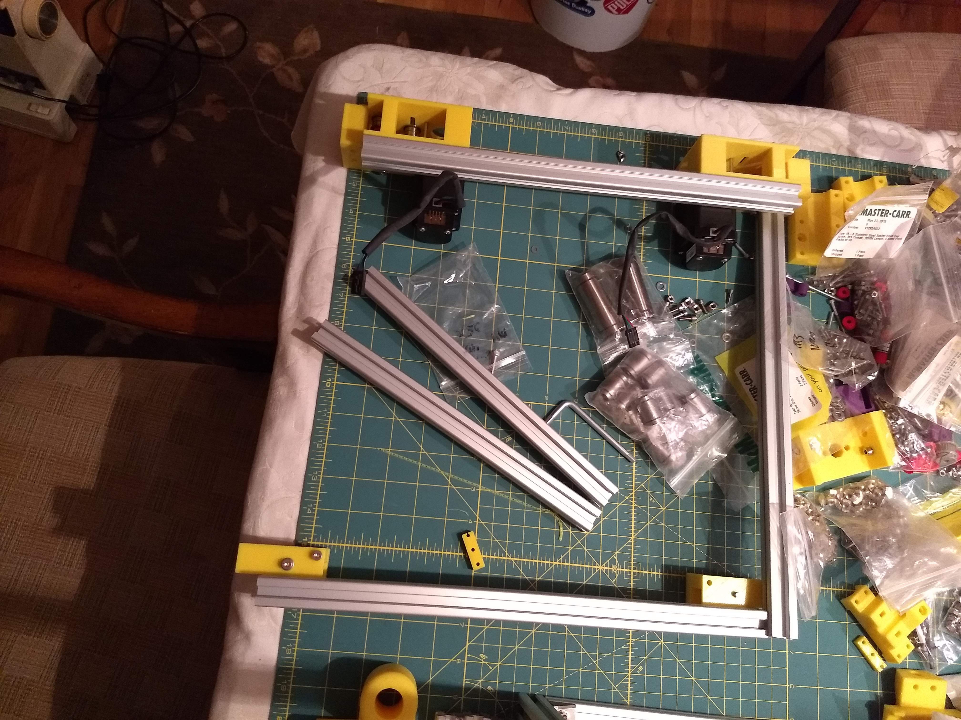
Cut Extrusion and Printed Parts
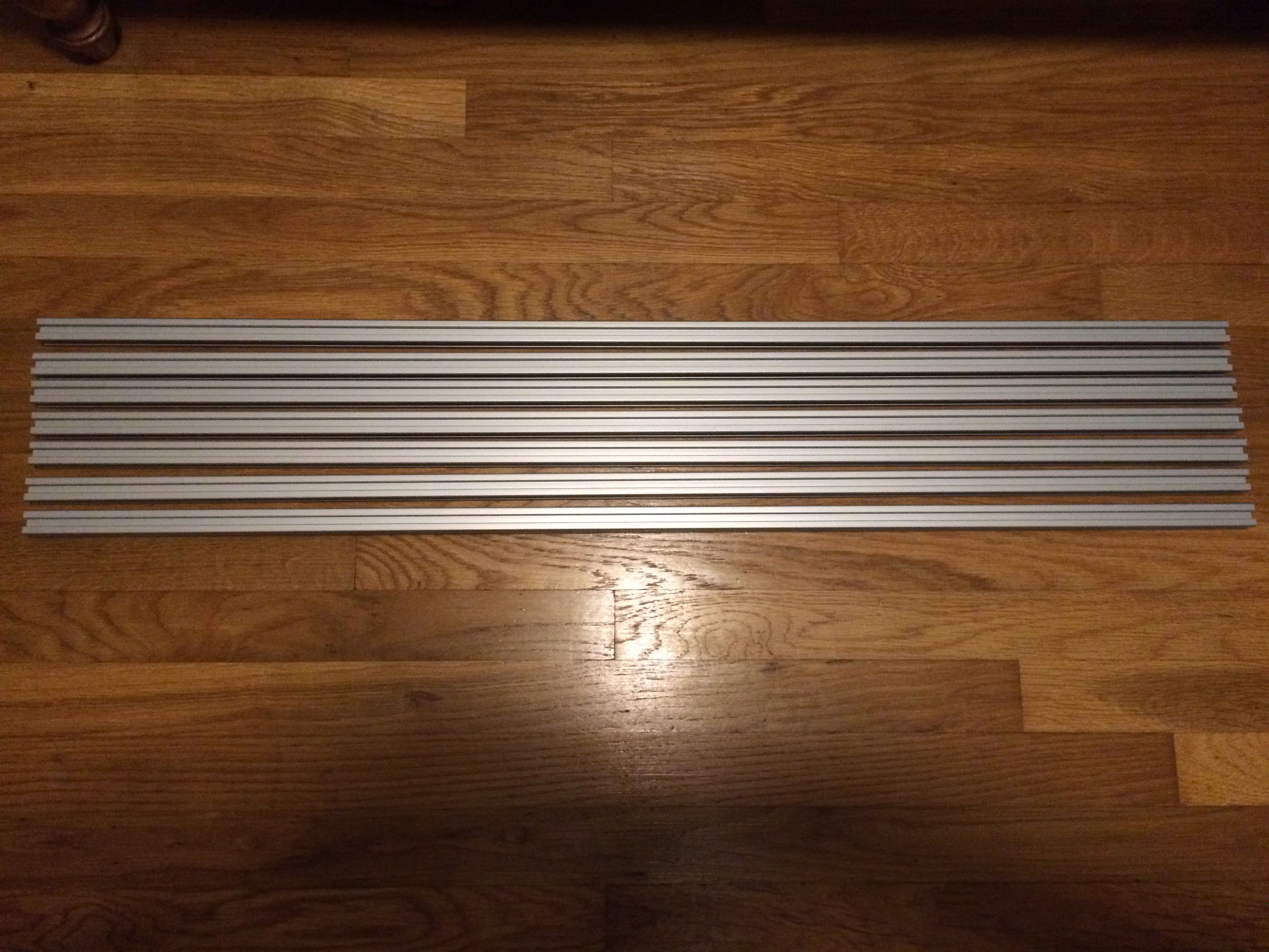
02/05/2016 at 16:13 • 0 commentsThe Aluminum has been cut and the parts have been printed for one printer.
![]()
You will need about 7m of stock to make this.
![]()
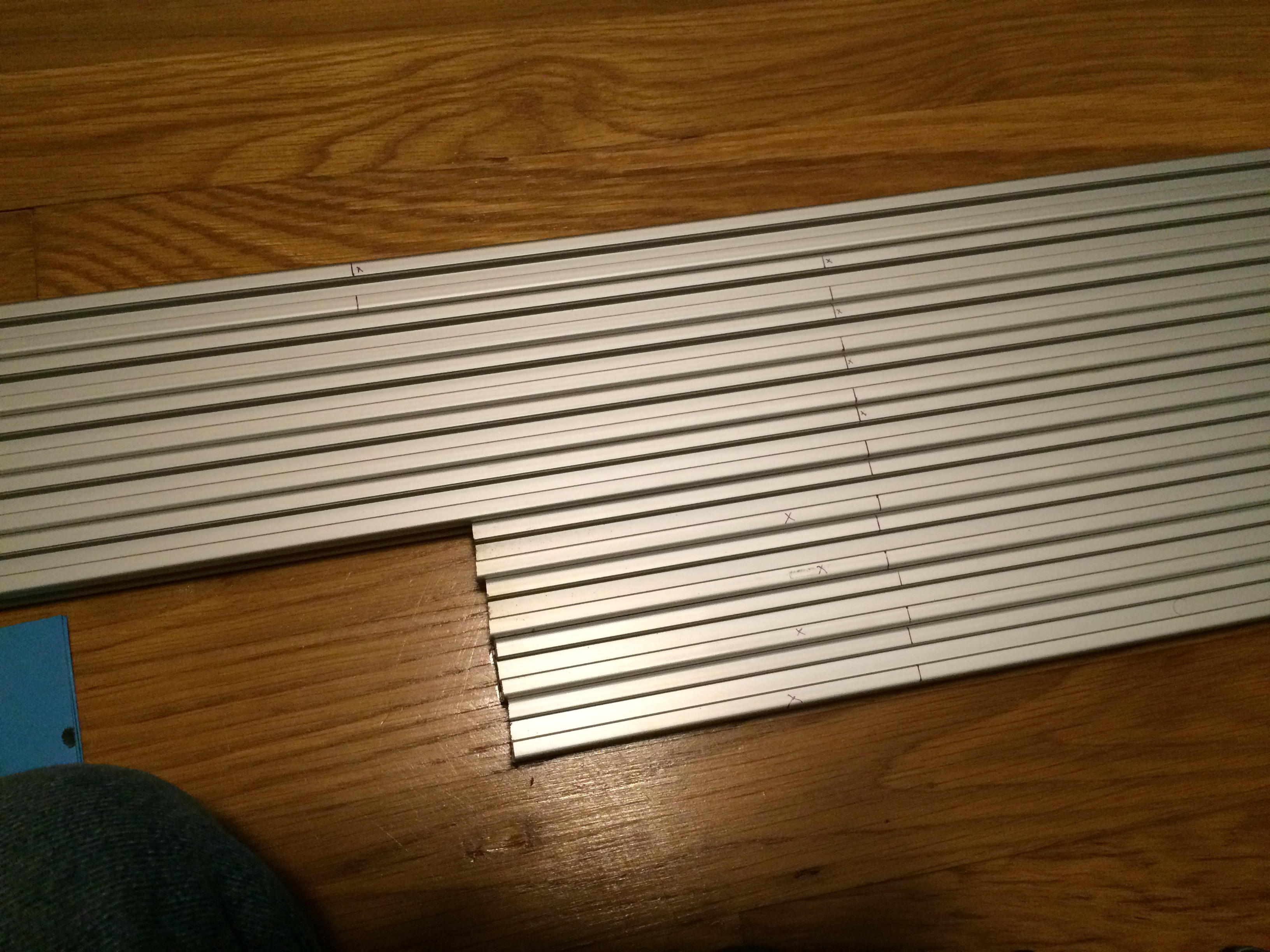
Everything marked out for the first cuts. Make sure to mark your waste end to account for the blade kerf.
![]()
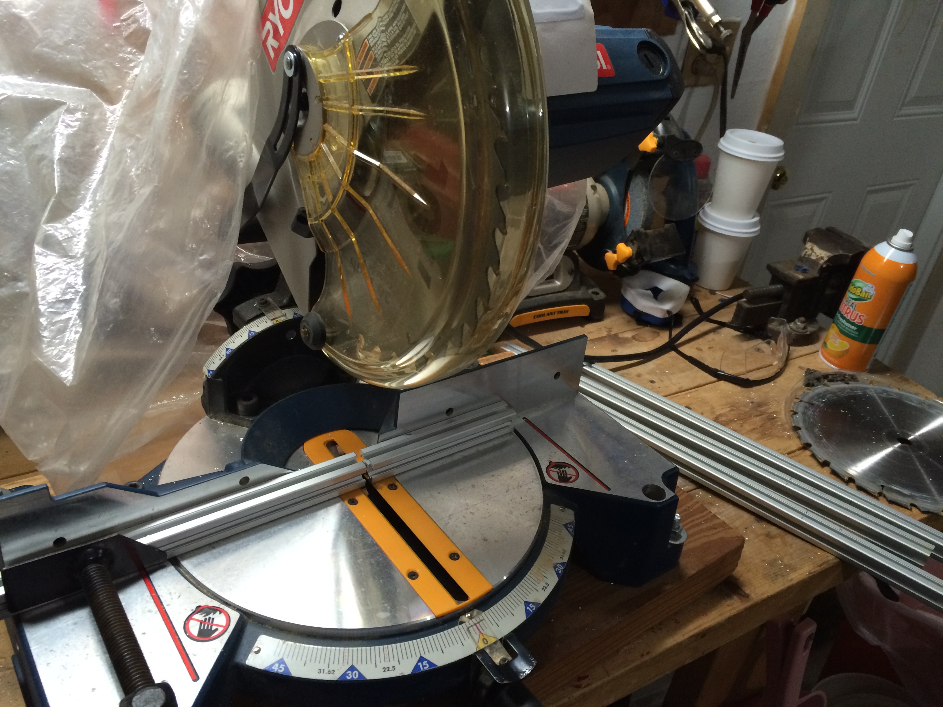
"You need a metal cutting saw blade" they said "It will wreck your extrusion" they said. Nonsense! All you need is carbide teeth and a slightly higher tooth count blade. I couldn't tell which ends were my cuts and which were factory cut.
![]()
4x 500mm, 8x 360mm, 2x 330mm.
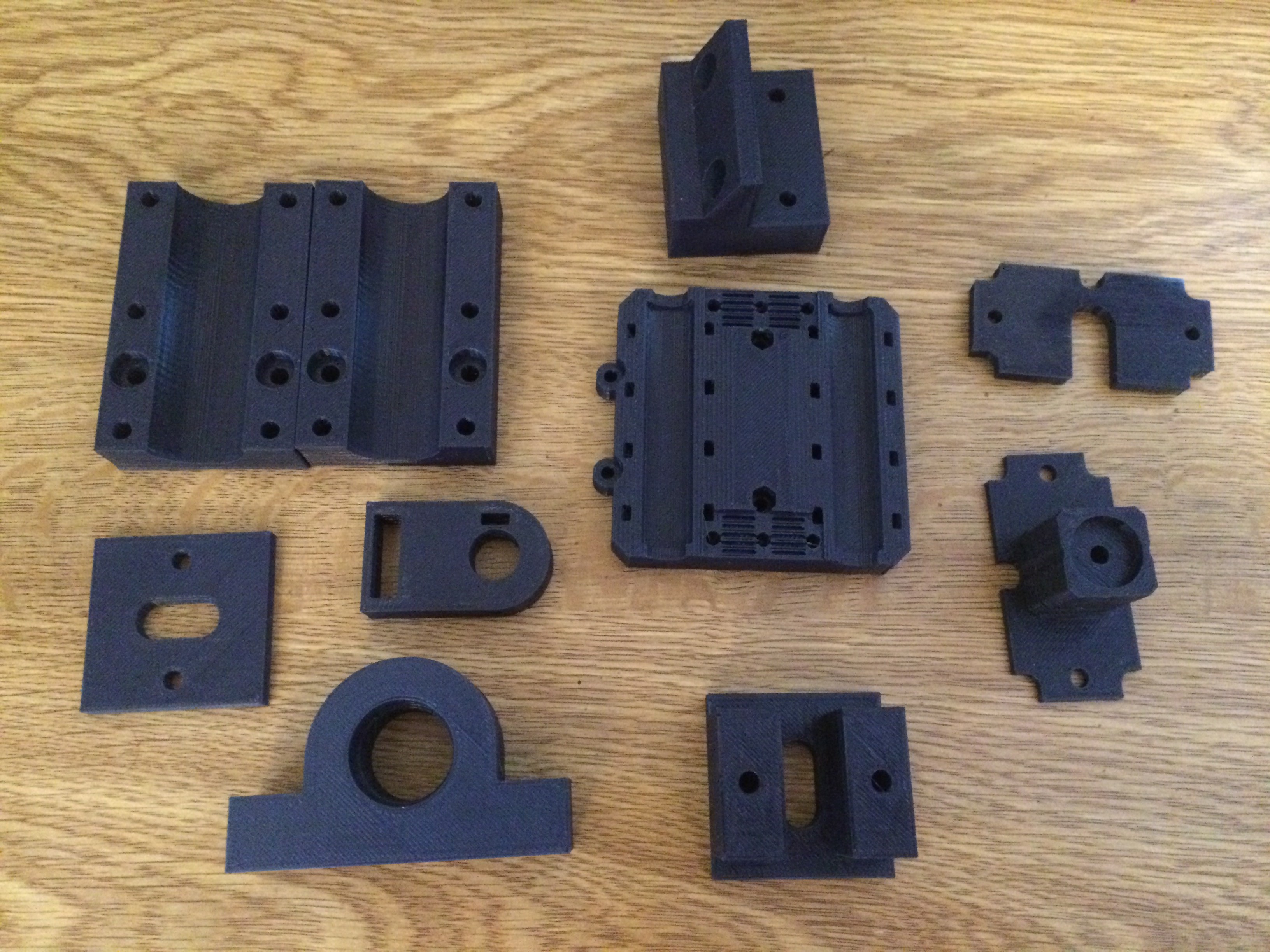
![]()
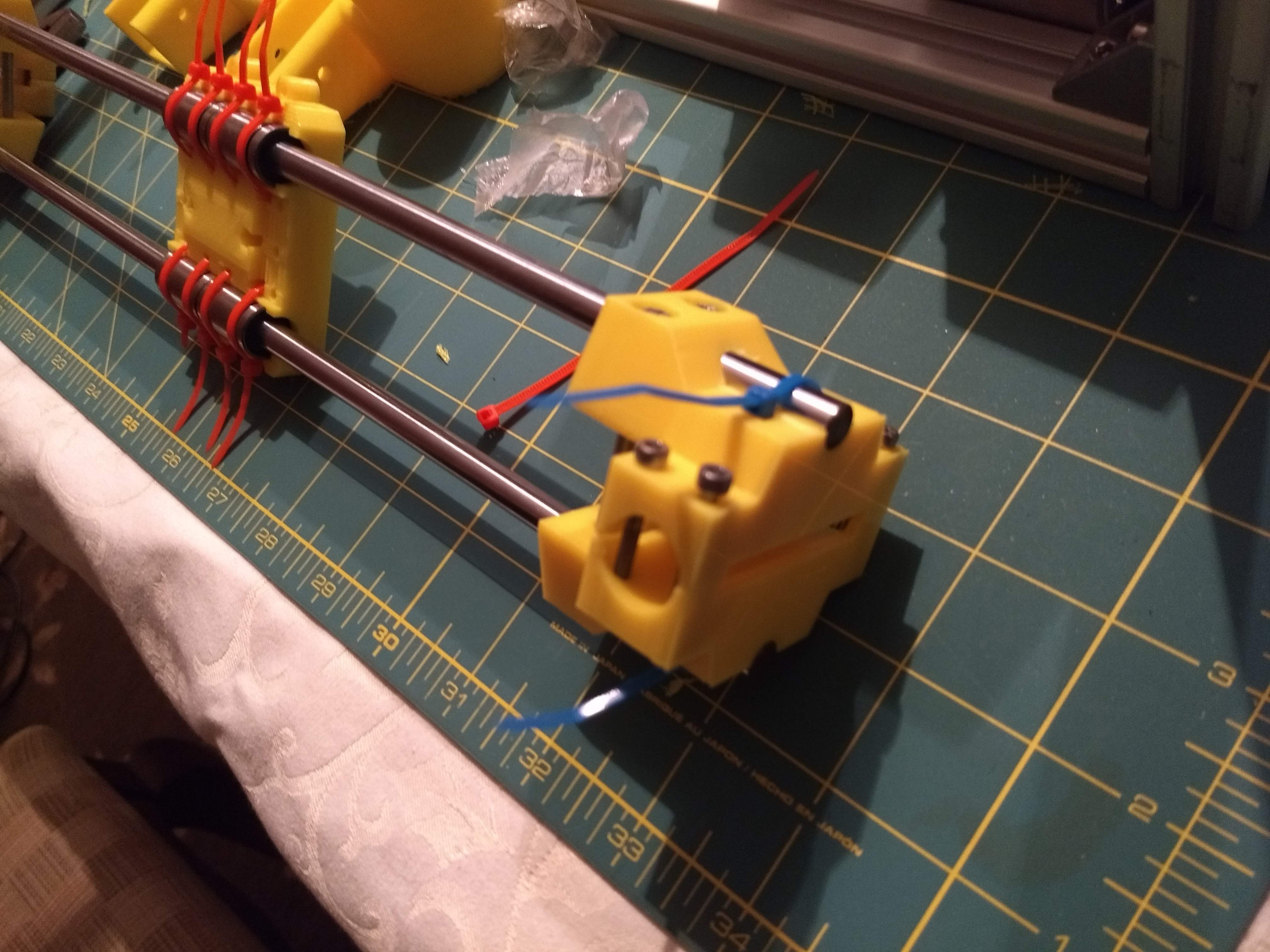
Photo Dump of printed parts. Customized the X-Carriage (Center) to fit bushings.
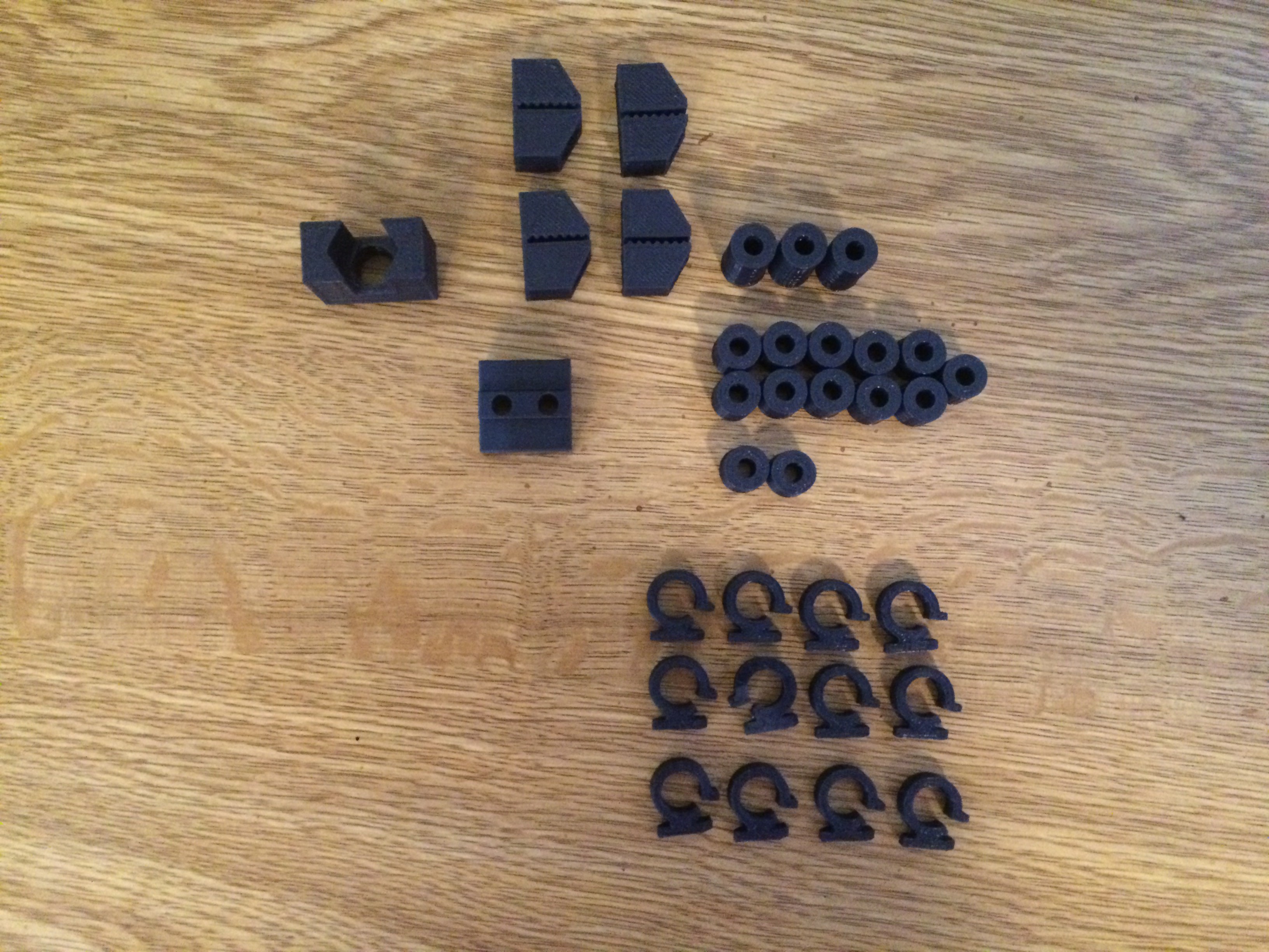
![]()
Clips, standoffs, and belt grips.
![]()
Motor and Idler block tops and bottoms.
![]()
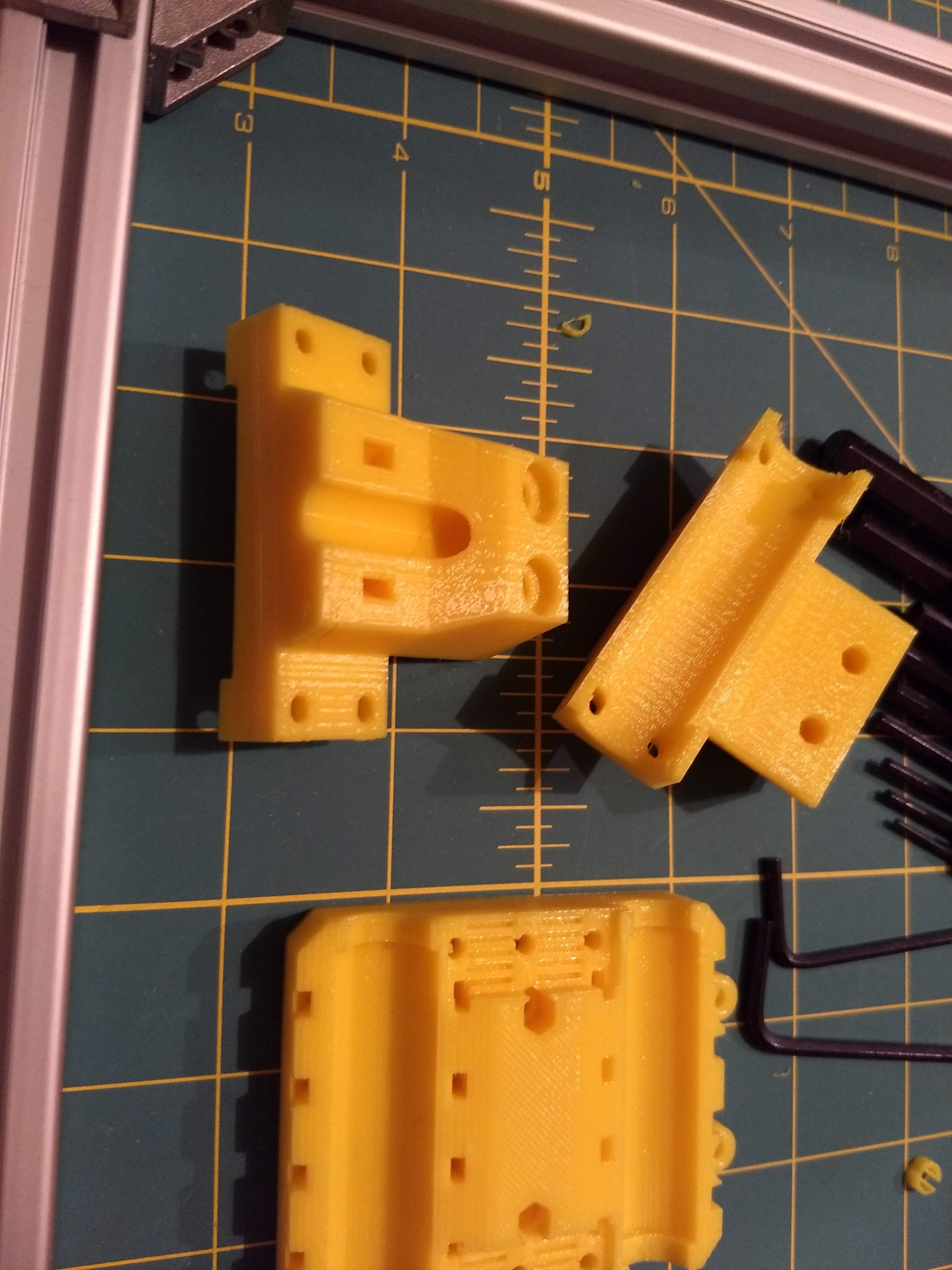
Z Blocks, Z Motor Mounts, and Motor Spacers
![]()
XY blocks modified to fit bushings, and Z-axis clamps
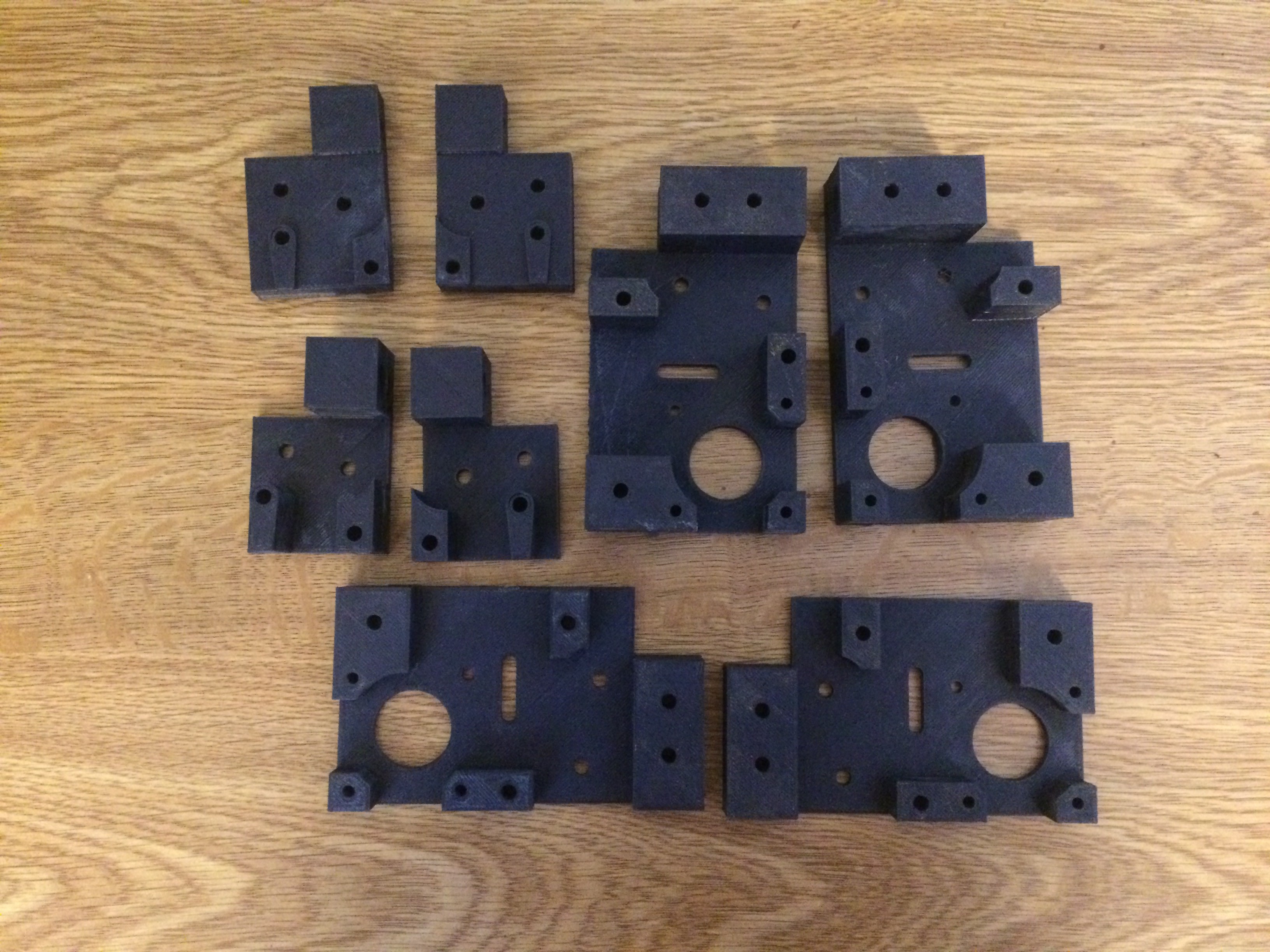
![]()
Inner Corner Brackets, Outer Corner Supports, and power supply mounts.
Waiting on some more hardware to roll in, then we are going to get to building!
-Will F
-
Introducing RepRap-XY Iteration 2
01/17/2016 at 06:28 • 0 commentsRepRap-XY Iteration 2 is a fork of the RepRap-XY printer designed by Jand on the RepRap forums, his design is a 3D printable adaption of Zelogik's machined aluminum CoreXY 3D printer. RepRap-XY is essentially a RepRappable version of Zelogik's printer, Iteration 2 began as a fork of Jand's git repo for RepRap-XY. Iteration 2 incorporates several community modifications and some original modifications/improvement.
The community modifications to the design are primarily the the gantry system, the gantry used in Iteration 2 is the vertical rod design found in Sdavi's fork of Jand's RepRap-XY. The vertical rod design is a bit more rigid, allows for nice mounting options, and a nice path for the belts (between the rods). This mod replaces the XY blocks and carriage of the printer. Modifications introduced by ourselves in Iteration 2 include:
- motor spacers for adjusting offset of the motor boxes and idler boxes to line up with the new gantry
- 2020 T-slot corner brackets
- inner corner brackets for 2020 T-slot
- motors mounted tops side
- Z motor bottom mounted
- Z axis leadscrew replaced with OpenBuilds 8mm Leadscrew and Delrin Nut Plate
- More unified Z axis design for increased rigidity
- mounting hardware for the E3D family of hotends.
Currently the CAD is under heavy development and an iteration of the design has been printed and is pending construction. CAD work is currently focused on designing mounting hardware for hotends and electronics. Be sure to follow the github repository for updates.
RepRap-XY Iteration 2
A Redistribution of Jand's RepRap-XY CoreXY 3D printer, integrating modifications by sdavi and original modifications for improvement


 Test Print specs: PLA 40% infill 1.2mm perimeters, 0.2mm layer height.