-
BIGHID button
06/12/2016 at 17:51 • 0 commentsA simple application for USBreadboardIT is the BIGHID button (that is, a BIG HID button). It emulates an USB HID keyboard (so, no drivers) annd sends a single keypress or key combination, that can be bound to an usOr-defined action.
It is based on two excellent pieces of software:
- The m-stack USB open source stack by Signal11, that emulates the USB HID keyboard (specific code here)
- The PIC16F1-USB-DFU-Bootloader by majbthrd, that allows for dfu firmware updates through dfu-util
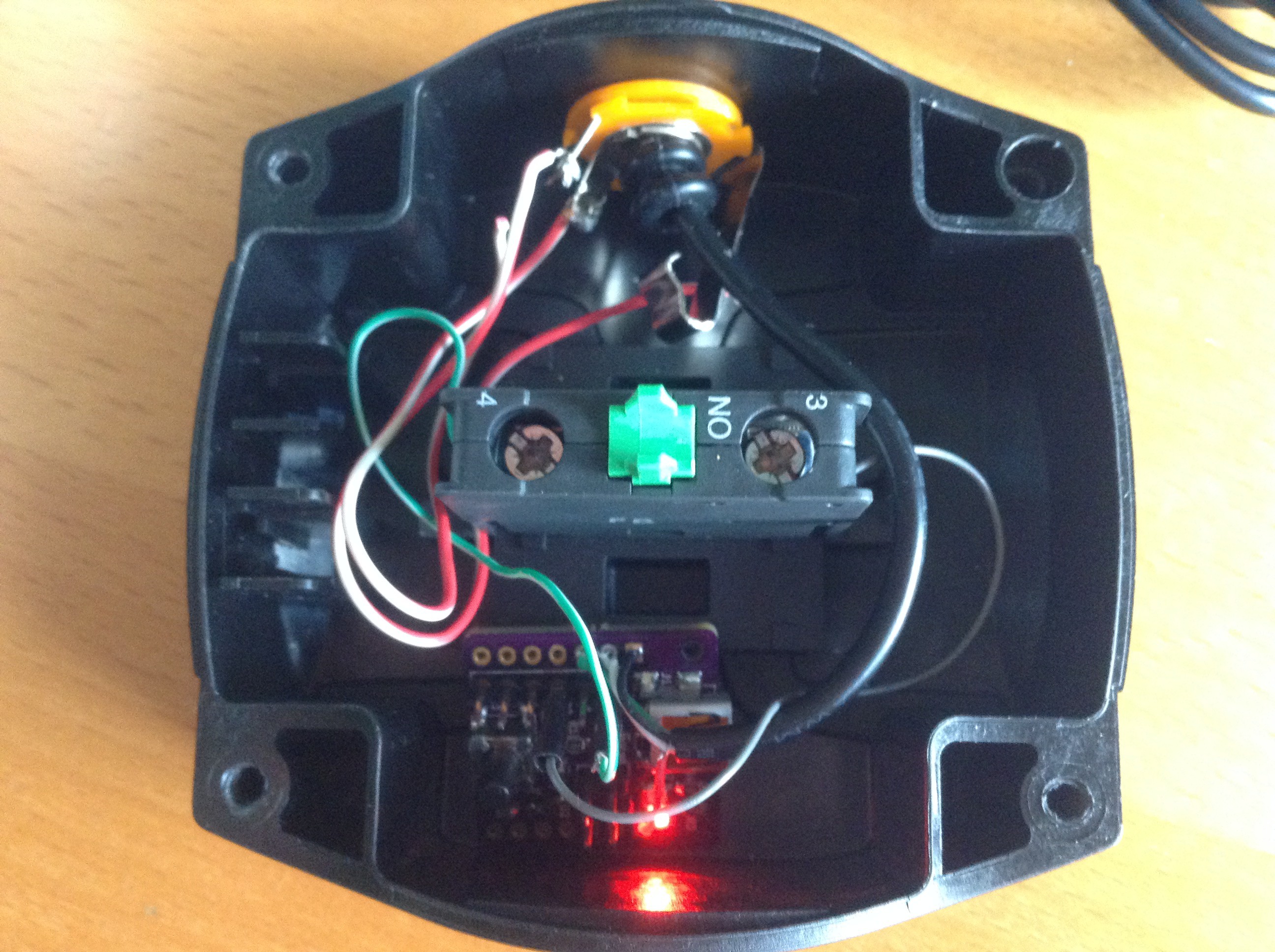
The hardware part is very simple: a button is tied between a pulled-up input pin (RA3) of the board and GND. A USB cable is connected to corresponding signalls on the headers.
![]()
The first software step has been performed uploading the DFU bootloader through a pickit2.
Once the bootloader is working, connecting the usb cable to the PC while holding the button pushed exposes the bootloader to the OS and dfu-util can be used to upload code to the board.
Code has to be compiled in MPLABX with the following options:
--codeoffset=0x200
--rom=default,-0-1FF,-1F7F-1F7F
Produced HEX file must be converted to proper dfu file through 454hex2dfu (included into bootloader repo):
454hex2dfu MPLAB.X.production.hex hidkbd.dfuThen the obtained dfu file can be uploaded with
dfu-util -D hidkbd.dfu
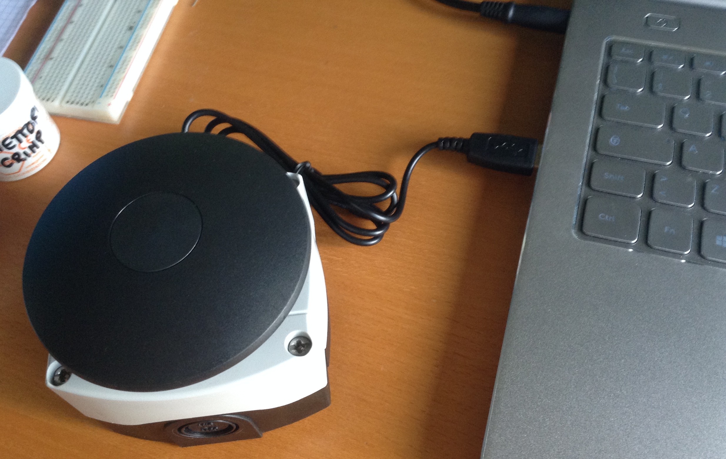
The button has then to be connected and re-connected to start keyboard operation.
![]()
The firmware polls RA and sends CTRL+SHIFT+1 when the button is pressed. OS bindings are then used to catch this combination.
-
Wrong pinout!
06/11/2016 at 13:41 • 0 commentsI noticed today that published pinout where not correct: USB D- and D+ pins were swapped in the image.
Issue has been corrected.
-
Board is working!
11/01/2015 at 16:47 • 3 commentsBoard is working! The classical blinky test past smoothly and now an initial version of the test - and maybe other usages - firmware is ready and uploaded on Github: Link
-
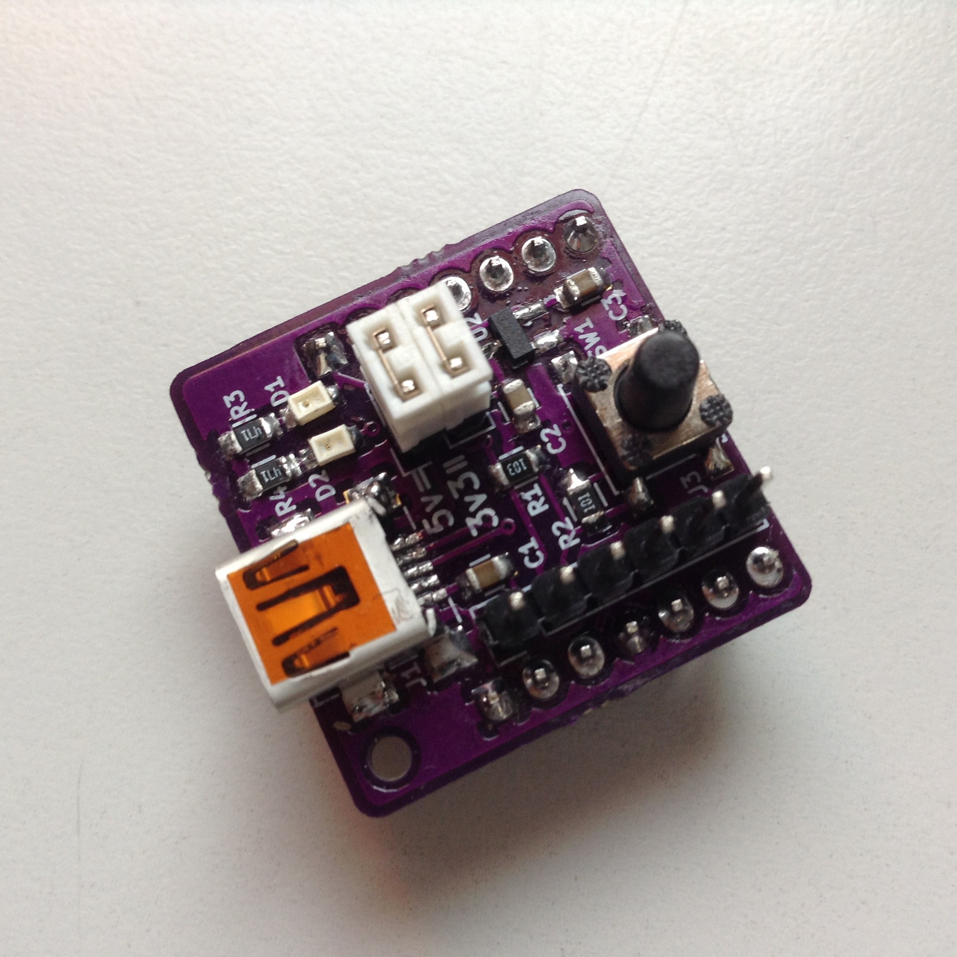
USBreadboardIT assembled and ready for testing
10/26/2015 at 12:54 • 0 commentsI assembled the first USBreadboardIT unit, completely by hand (have I mentioned that USBreadboardIT have been thought with hand-assembly in mind?). D1, that is the "power" LED tied to VDD, lights up when connected to power, so at least the power works, both at 5v and 3.3v :)
Regarding the microcontroller, I used a PIC16F1454 because it's bigger brother PIC16F1455 (with analog capabilities added) was out of stock when I tried to order it. They are pin-compatible, so USBreadboardIT will work anyway.
![]()
-
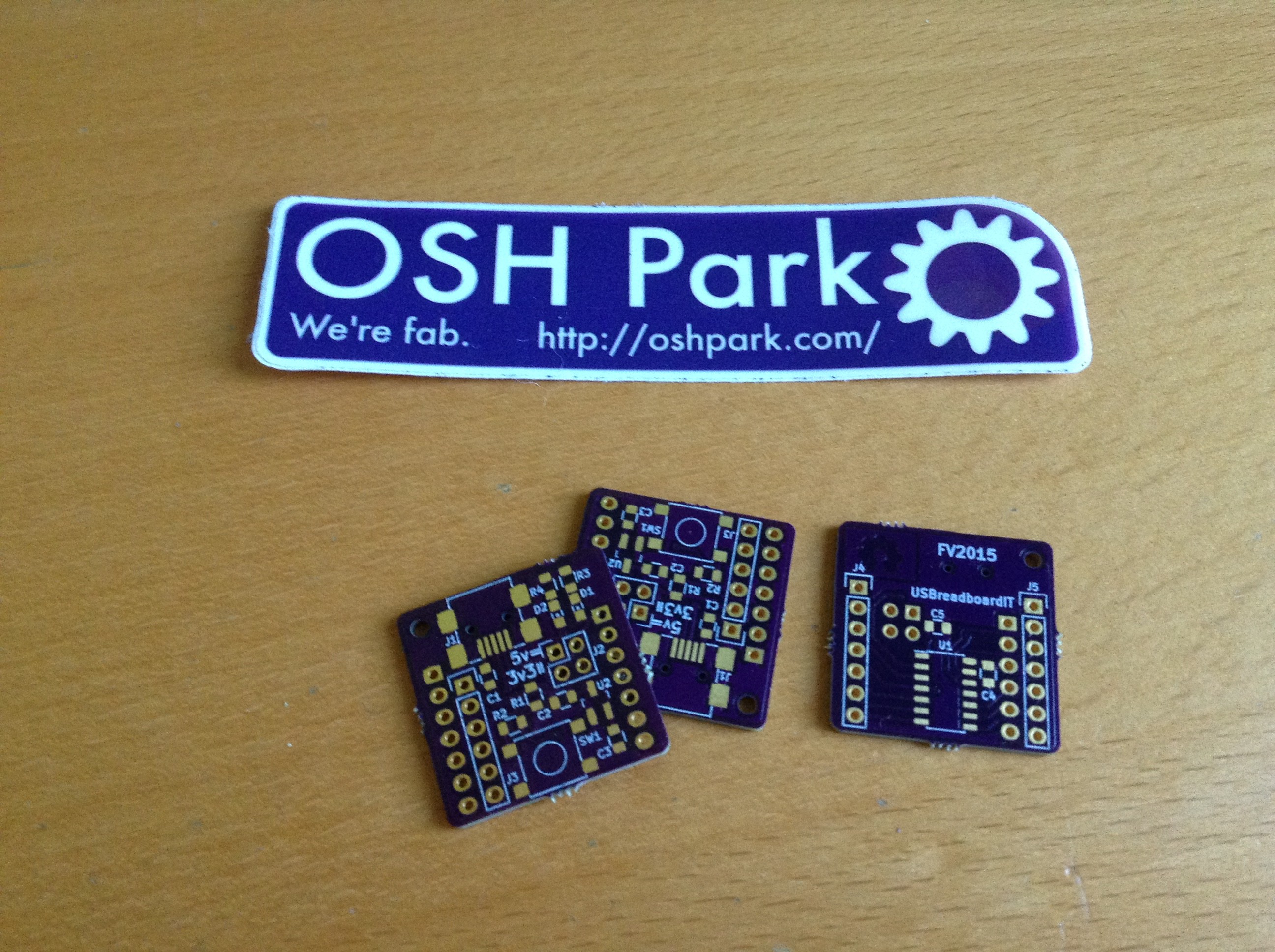
PCBs arrived!
10/26/2015 at 11:24 • 0 commentsWonderful purple PCBs arrived from OSHpark, time to assemble USBreadboardIT!
![]()
-
PCB sent to production! Plus test software
10/08/2015 at 19:48 • 0 commentsYesterday I sent the PCB to OSH Park! It should arrive in one month (manufacturing plus shipping to Italy).
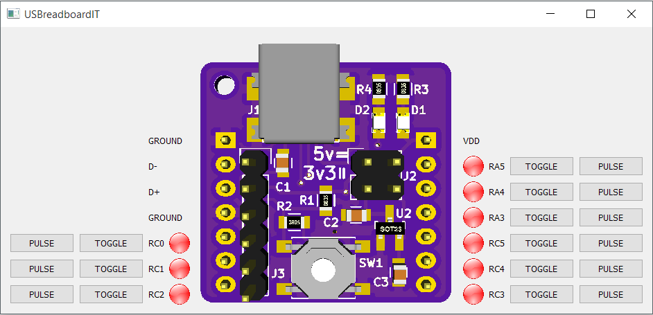
I uploaded on Github the design files (kicad source plus gerber), together with a - unfinished - test application (written in python plus Qt) to control the board through USB HID.
![]()
-
Small board modifications
10/05/2015 at 10:08 • 0 commentsAfter some digging, I found an interesting USB bootloader fitting in only 512 words for PIC16F1455:
https://github.com/majbthrd/PIC16F1-USB-DFU-Bootloader
For this to work I have to add to the board a pushbutton on RA3 (the same pin as reset) and thus rrearrange the board a bit; after that I will send the board in production.
Stay tuned!