AndyMac
-
Building the Arduino Shield
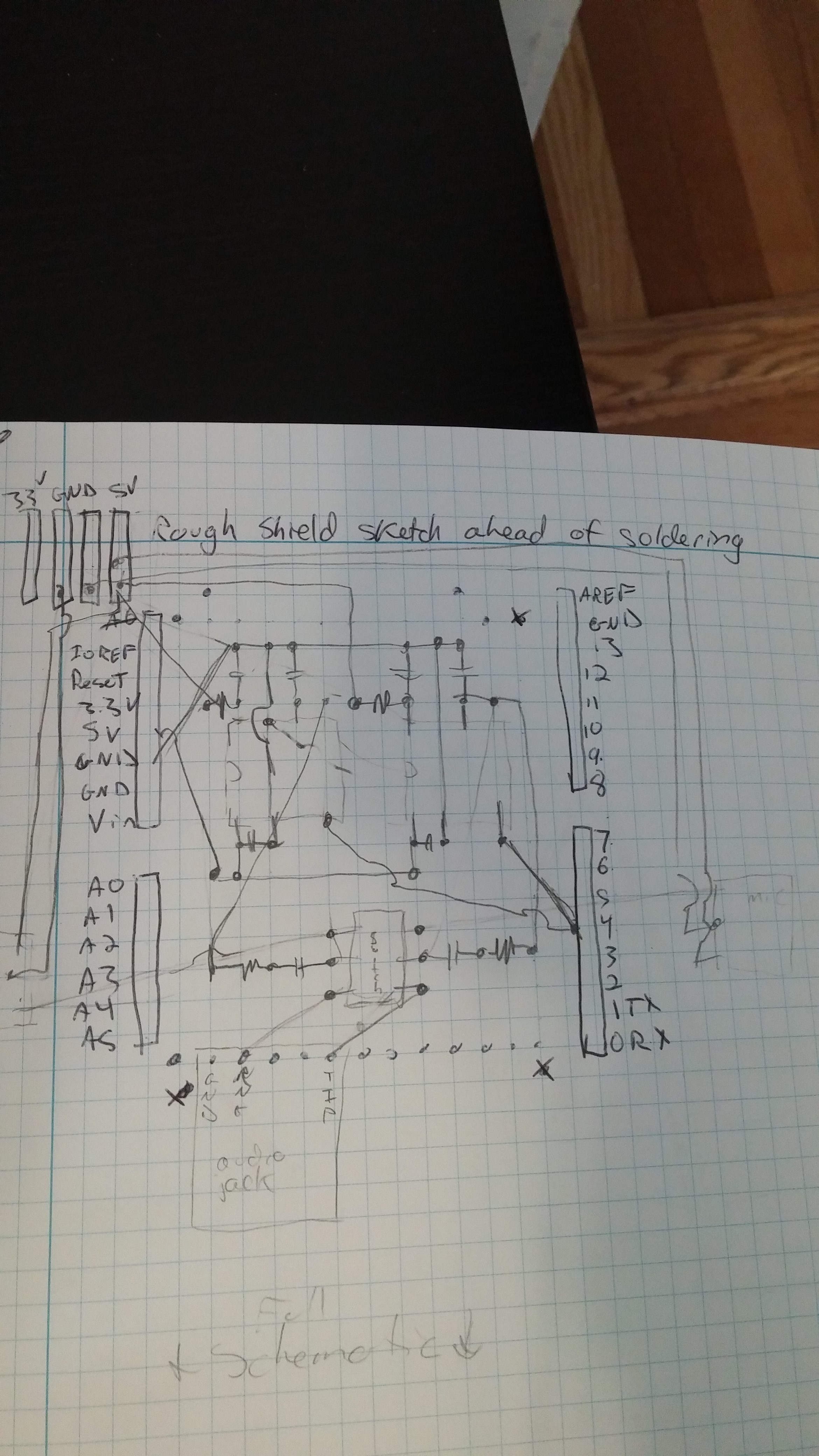
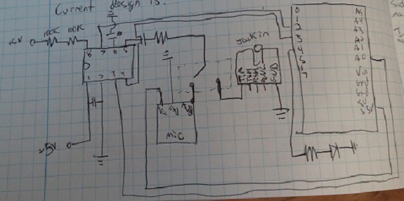
05/01/2016 at 18:39 • 0 commentsThe build would have to be put together in several parts. A prototyping shield on top of the Arduino would hold most of the circuitry, including the all-important MSGEQ7s, an input for an 1/8" audio jack (for direct audio input instead of the microphones), and a toggle switch between the two. The microphones would be mounted on long wires to each side of the hat as "ears" to provide some amount of directional sensing. A separate "power supply board" would include the two large capacitors used to protect the NeoPixels. Battery packs would be located off to the side. I wanted a rough schematic to work off of while assembling, but the final product has a few differences from the one below.
![]()
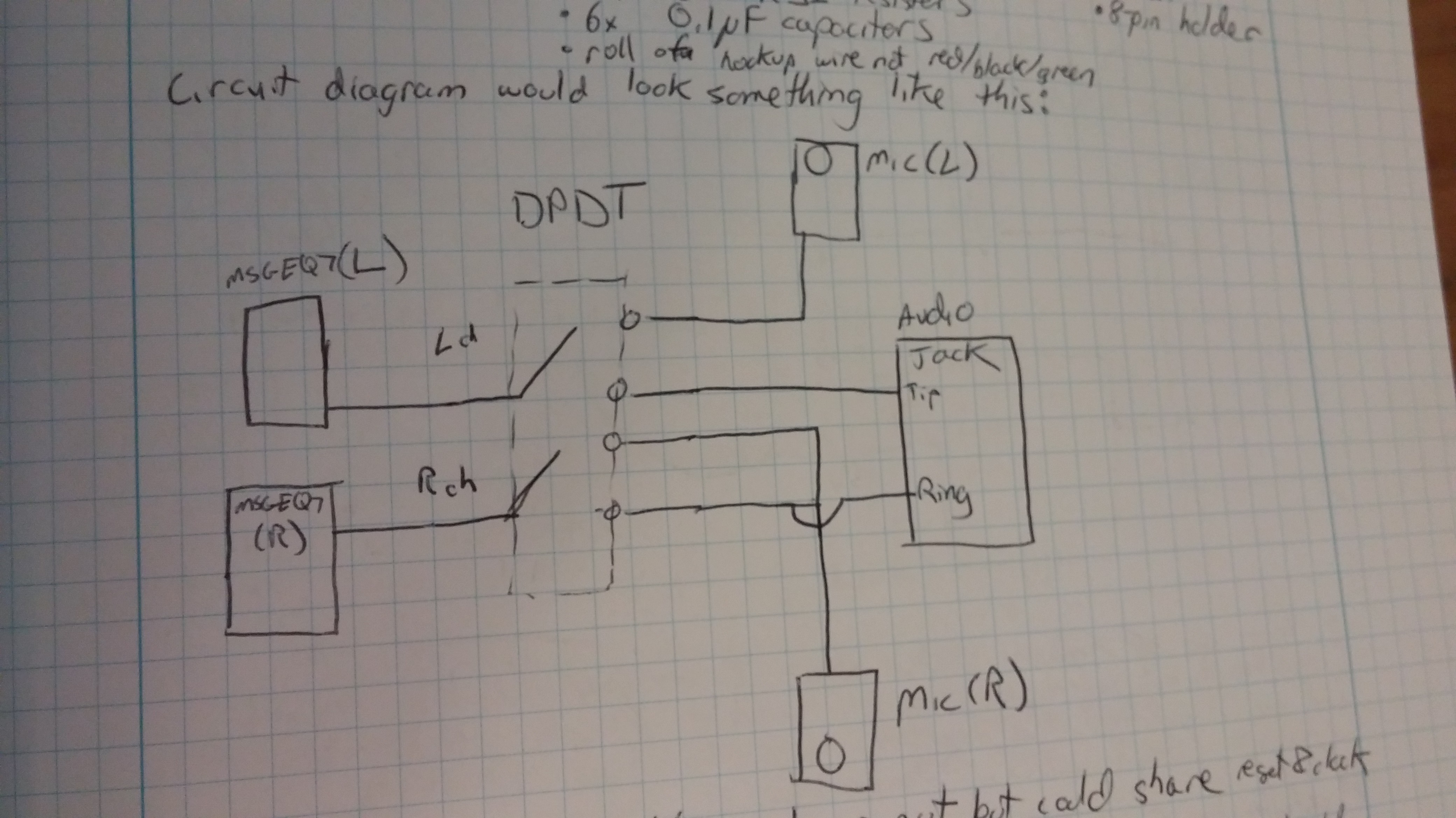
A generalized sketch of how the audio inputs work is seen below. I wanted to have two microphone inputs to be analyzed separately, as well as a standard 1/8" audio jack, with a select switch to change between the two.
![]()
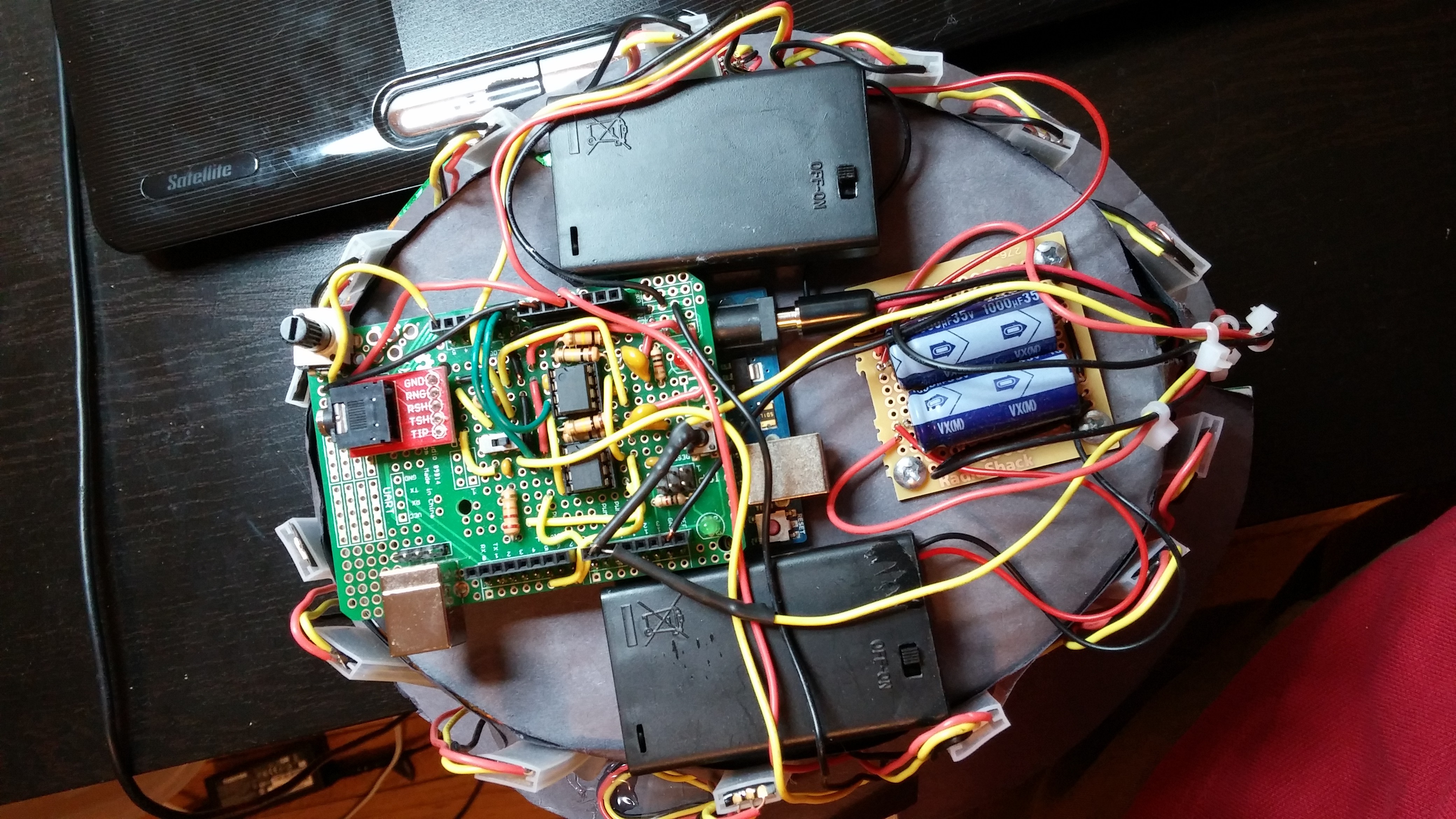
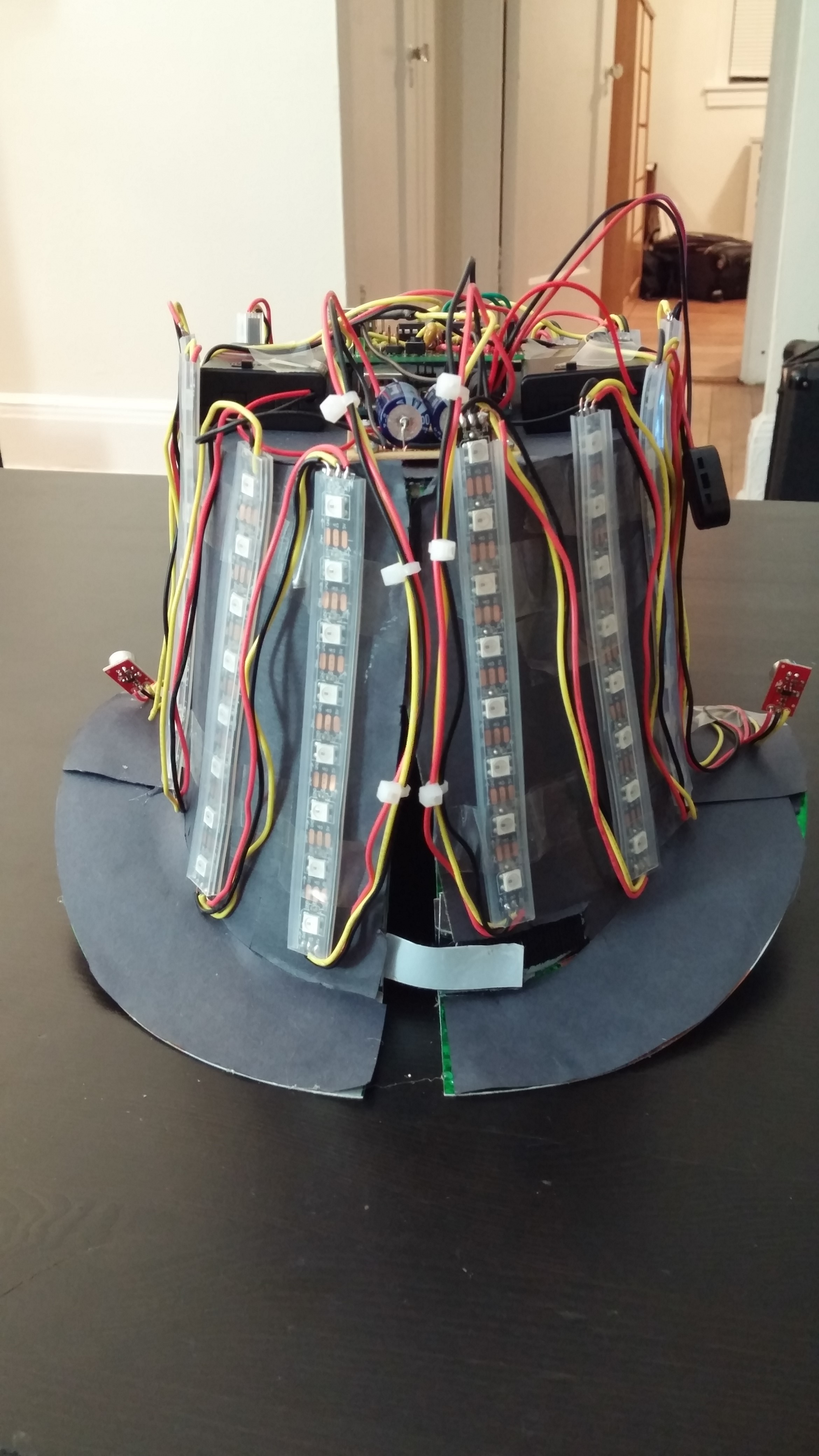
This is a shot of the assembled circuit. This circuit had to last through several full day competitions, as well as a week long Global Finals, so I went a little overboard on the batteries. The two packs on top of the hat power each strip of NeoPixels, one for left channel and one for right channel. If the input is loud and/or constant most of the LEDs would be lit up, so the power requirements are actually fairly heavy. At 14 strips, 8 pixels per strip, and 200 mA max draw, the theoretical max is 19.6 A! Obviously by running the lights in Red-Green-Yellow I could limit the max to 1/3 of that, and a maximum brightness would turn it down even further, but that is still a decent amount of power to be carrying around on my head.
The protoboard on the left is mounted on top of the Arduino and does all audio analysis, sending display info to the NeoPixel strips. A third battery pack underneath the hat (not shown) provides power for the Arduino. There is a 10KOhm trimpot on the upper-left hand corner of the shield that was not in the original plan. This was used as a real-time adjustable gain so the hat would work well in both loud and quiet environments.
![]()
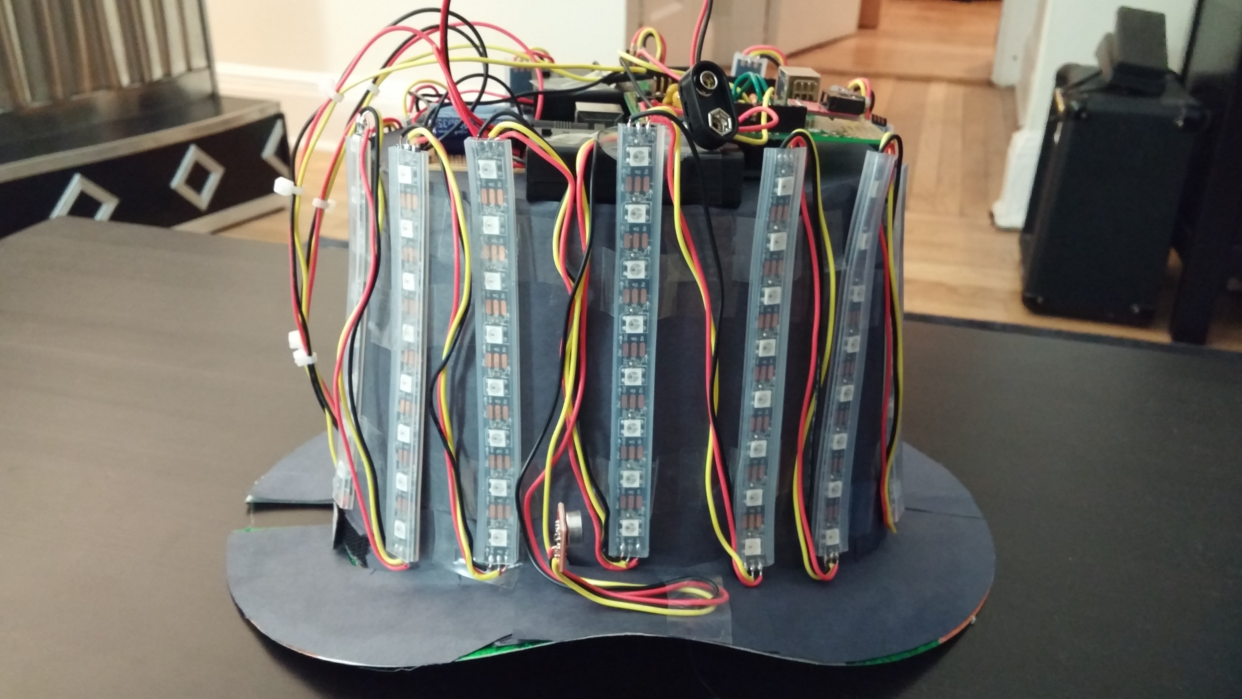
The toughest part of assembly was actually attaching the NeoPixel strips. The silicone cover on each strip does not stick to ANYTHING. As a temporary measure I just ran clear tape across them and onto the hat itself. It was not meant to be a permanent method, but ended up working well enough and held together over the few days I needed it to.
![]()
The hat itself is a cheap cardboard top hat from Party City (the green strips visible under the construction paper gives it away as a St. Patrick's Day hat). Those hats fit very poorly, but a slit up the back with some Velcro (ahem, "hook-and-loop") actually turns it into a very wearable fashion accessory. You can also see the two microphone "ears" on each side of the hat.
![]()
Finally, the test. The hat works remarkably well. Some tweaking was needed to the gain in each strip: the high and low frequencies did not show up well. I ended up with 1.5 - 1.5 - 1 - 1 - 1 - 1.5 - 1.5 just to boost the ends a bit. The song is "Valerie" by the Zutons.
The hat was always intended to work during the daytime, and luckily the NeoPixels are bright enough, even at 1/4 brightness.
The cymbal crash in the beginning of Marvin Gaye's "Let's get it on" really hits well on this project.
-
Complete Circuit Prototype
10/05/2015 at 03:48 • 0 commentsBefore putting together the final circuit I put (mostly) everything together on a protoboard. Halfway through the project I found a great resource in Imgur user [omenSP]'s http://imgur.com/a/jYhRk. Before I invested in the NeoPixel strip I tested the circuit with a pixel ring I had onhand.
Once I got the complete strip in I realized I had to cut and resolder for the hat. Every time I work with these pixels I burn out or otherwise damage a pixel. Because of the design I had to cut and resolder the strip. One final test before soldering the complete board:
The code I used is below. Credit for large portions of the code goes to [omenSP].
/* Test #3 adds neopixel ring for visual representation and responsiveness MSGEQ7 bands = 63Hz, 160Hz, 400Hz, 1,000Hz, 2,500Hz, 6,250Hz, 16,000Hz Most of this was inspired by http://pastebin.com/4hHQfq49# & http://imgur.com/a/jYhRk http://www.eetimes.com/author.asp?section_id=216&doc_id=1323030 I'm sure there is a better way to split L&R channels (omenSP's code averages them for 1 EQ). For right now I did it fairly manually by doubling up on nearly every variable At the moment I am sharing strobe and reset pins across both MSGEQ7 chips */ //------------------------------------LIBRARIES--------------------------------- #include <Adafruit_NeoPixel.h> // NeoPixel Library #include <Event.h> // Comes with Timer.h library? #include <Timer.h> // Timer library #include <math.h> // Math library //------------------------------------PIN DECLARATIONS--------------------------------- //int ctrlReset = 2; // Digital pin 2 = signal to reset MSGEQ7s //int ctrlStrobe = 3; // Digital pin 3 = signal to strobe (read data from) MSGEQ7s //int Led4 = 4; //LED to light up and test 1 band const byte dataPinL = 8; // Data pin for Neopixels const byte dataPinR = 9; // Data pin for Neopixels //int channelLeft = A0; // Analog pin 0 = spectrum data from left channel //int channelRight = A1; // Analog pin 1 = spectrum data from right channel const byte analogPinL = A0; // left channel analog data from shield const byte analogPinR = A1; // right channel analog data from shield const byte strobePin = 4; // data strobe for shield const byte resetPin = 5; // reset strobe for shield //------------------------------------VARIABLES/CONSTANTS DECLARATIONS--------------------------------- //int spectrumLeft[7]; // Array to store 7 bands of spectrum data from left channel //int spectrumRight[7]; // Array to store 7 bands of spectrum data from right channel const byte numBand = 16; // Number of LEDS per band. **change for strip const byte numTop = 0; // The number of LEDs to have top color int peakArrayL[7]; // Holds peak values for each of the 7 bands int peakArrayR[7]; // Holds peak values for each of the 7 bands Timer t; // Timing variable String colorPick = "GreenYellowRed"; //Select color palette for EQ. See uint32_t Wheel int spectrumReadR; //R magnitude from shield int spectrumReadL; //L magnitude from shield //int audio = MONO; //set audio mode to mono, combine R&L channels **dunno what this does int magL = 0; //the magnitude of a freq band int magR = 0; //the magnitude of a freq band int numONL = 0; //the number of LEDs on in a freq band int numONR = 0; //the number of LEDs on in a freq band float fl_magL = 0.0; //floating point mag after noise removal and scaling float fl_magR = 0.0; //floating point mag after noise removal and scaling const int noise[] = {1, 1, 1, 1, 1, 1, 1}; // set this to magnitude of noise from shield const float gain[] = {1.0, 1.0, 1.0, 1.0, 1.0, 1.0, 1.0}; // - gain for each band const unsigned long loop_dlay = 35; // loop delay to slow down display update rate byte //**not the faintest idea what this does, and i feel like it will throw an error peak = 0, dotCount = 0; Adafruit_NeoPixel stripL = Adafruit_NeoPixel(numBand, dataPinL, NEO_GRB + NEO_KHZ800); //**mult #pins for strip? Adafruit_NeoPixel stripR = Adafruit_NeoPixel(numBand, dataPinR, NEO_GRB + NEO_KHZ800); //**mult #pins for strip? void setup() { Serial.begin(9600); /*-------------FROM OLD PROGRAM-------------- pinMode(ctrlReset,OUTPUT); // Define reset as output pinMode(ctrlStrobe,OUTPUT); // Define strobe as output pinMode(Led4,OUTPUT); digitalWrite(ctrlReset,LOW); // Pull the reset signal low digitalWrite(ctrlStrobe,HIGH); // Drive the strobe signal high digitalWrite(Led4,LOW); */ pinMode(resetPin, OUTPUT); pinMode(strobePin, OUTPUT); pinMode(dataPinL, OUTPUT); pinMode(dataPinR, OUTPUT); // Start strip communication and start them at 1/4 brightness and blank stripL.begin(); stripR.begin(); stripL.setBrightness(64); // Control strip brightness **see how well it works in a lit room stripR.setBrightness(64); // Control strip brightness **see how well it works in a lit room stripL.show(); // Initialize all pixels to 'off' stripR.show(); // Initialize all pixels to 'off' digitalWrite(resetPin,HIGH); delayMicroseconds(5); digitalWrite(strobePin,HIGH); delayMicroseconds(50); // strobe PW > 18 usec min digitalWrite(strobePin,LOW); delayMicroseconds(50); //reset PW > 100 usec min digitalWrite(resetPin,LOW); delayMicroseconds(5); digitalWrite(strobePin,HIGH); delayMicroseconds(100); // allow reset to strobe falling > 72 usec min t.every(100,peakLower); // calls peakLower function every 100 ms **(why?) (or 10ms?) } /*void loop() //---------VOID LOOP FROM OLD PROGRAM--------------- { readMSGEQ7(); //-----------debug lines from the old program. update this, b/c it could be helpful-------------- // Display values from the left channel on the serial monitor for (int i = 0; i < 7; i++) { if (spectrumLeft[i] < 100) Serial.print(" "); if (spectrumLeft[i] < 10) Serial.print(" "); Serial.print(spectrumLeft[i]); Serial.print(" "); } Serial.print(" "); // Display values from the right channel on the serial monitor for (int i = 0; i < 7; i++) { if (spectrumRight[i] < 100) Serial.print(" "); if (spectrumRight[i] < 10) Serial.print(" "); Serial.print(spectrumRight[i]); Serial.print(" "); } Serial.println(); //-------LED DEBUG FROM OLD PROGRAM. PROBABLY DELETE THIS--------- if (spectrumLeft[4] > 100) digitalWrite(Led4,HIGH); else digitalWrite(Led4,LOW); } */ /*-------------THE READ FUNCTION FROM EETIMES PROGRAM. USING omenSP's FOR NOW--------------- void readMSGEQ7() { // Read the seven spectrum bands from the MSGEQ7 chips digitalWrite(ctrlReset, HIGH); // Pulse the reset signal, which causes digitalWrite(ctrlReset, LOW); // the MSGEQ7s to latch the spectrum values delayMicroseconds(75); // Delay to meet minimum reset-to-strobe time for(int i=0; i <7; i++) // Cycle through the 7 spectrum bands { digitalWrite(ctrlStrobe,LOW); // Read current band (then increment to next band) delayMicroseconds(40); // Wait for outputs to settle spectrumLeft[i] = analogRead(channelLeft) / 4; // Store current values from left & right channels // spectrumRight[i] = analogRead(channelRight) / 4; // Divide 0-1023 by 4 to give 0-255 //Dividing by 4 is really for PWM output and I can probably eliminate that later digitalWrite(ctrlStrobe,HIGH); delayMicroseconds(40); // Delay to meet minimum strobe-to-strobe time } } */ void loop() { for(byte band = 1; band <= 7; band++) { digitalWrite(strobePin, LOW); //set analyzer to low to read delayMicroseconds(40); spectrumReadR = analogRead(analogPinR); //read right audio spectrumReadL = analogRead(analogPinL); //read left audio digitalWrite(strobePin, HIGH); //set analyzer back to high //---------NOT SURE WHY THIS SECTION IS IN BOTH LOOP() AND READBAND()--------- // mag = (spectrumReadR + spectrumReadL) / 2; magL = max(0, (magL - noise[band-1])); //creates magnitude of frequency magR = max(0, (magR - noise[band-1])); //creates magnitude of frequency fl_magL = gain[band-1] * float(magL); //adjusts magnitude for gain fl_magR = gain[band-1] * float(magR); //adjusts magnitude for gain numONL = map(fl_magL, 0, 1024, 0, numBand+1); //maps magnitude to number of active pixels numONR = map(fl_magR, 0, 1024, 0, numBand+1); //maps magnitude to number of active pixels anyBand(band); //Serial.print(band); //Serial.println(peakArray[band-1]); if(peakArrayL[band-1]==0) stripL.setPixelColor(peakArrayL[band-1] + numBand*(band-1), stripL.Color(0,0,0)); else stripL.setPixelColor(peakArrayL[band-1] + numBand*(band-1), stripL.Color(255,0,0)); if(peakArrayR[band-1]==0) stripR.setPixelColor(peakArrayR[band-1] + numBand*(band-1), stripR.Color(0,0,0)); else stripR.setPixelColor(peakArrayR[band-1] + numBand*(band-1), stripR.Color(255,0,0)); t.update(); } // strip.setBrightness(40); //I already did this up top. why do it again? stripL.show(); stripR.show(); delay(loop_dlay); } void readBand(byte band) { for(byte band = 1; band <= 7; band++) { digitalWrite(strobePin, LOW); //set analyzer to low to read delayMicroseconds(40); //minimum delay for MSGEQ7 spectrumReadR = analogRead(analogPinR); //read right audio spectrumReadL = analogRead(analogPinL); //read left audio digitalWrite(strobePin, HIGH); //set analyzer back to high //mag = (spectrumReadR + spectrumReadL) / 2; //average L and R spectrums to make mono magL = max(0, (magL - noise[band-1])); //creates magnitude of frequency magR = max(0, (magR - noise[band-1])); //creates magnitude of frequency fl_magL = gain[band-1] * float(magL); //adjusts magnitude for gain fl_magR = gain[band-1] * float(magR); //adjusts magnitude for gain numONL = map(fl_magL, 0, 1024, 0, numBand+1); //maps magnitude to number of active pixels numONR = map(fl_magR, 0, 1024, 0, numBand+1); //maps magnitude to number of active pixels anyBand(band); } } void anyBand(byte band) { // For each LED on a single freq band, turn on or off for(byte i = 0; i < numBand; i++){ // depending on if that freq was seen. Also provides if(i < (numONL - numTop - 1)){ // for a falling peak **that i may want to comment out stripL.setPixelColor(i + numBand*(band-1), Wheel(map(i,0,numBand-1,20,83))); //main wheel colors } else if(i >= numONL){ stripL.setPixelColor(i + numBand*(band-1), stripL.Color(0,0,0)); //unused colors on wheel } else{ if(i > peakArrayL[band-1]) peakArrayL[band-1] = i; //used for falling peak dot } } for(byte i = 0; i < numBand; i++){ if(i < (numONR - numTop - 1)){ stripR.setPixelColor(i + numBand*(band-1), Wheel(map(i,0,numBand-1,20,83))); //main wheel colors } else if(i >= numONR){ stripR.setPixelColor(i + numBand*(band-1), stripR.Color(0,0,0)); //unused colors on wheel } else{ if(i > peakArrayR[band-1]) peakArrayR[band-1] = i; //used for falling peak dot } } } void peakLower() { // **Not quite sure what this does yet for(byte i = 0; i < 7; i++) { if(peakArrayL[i] > 0) peakArrayL[i]--; if(peakArrayL[i] > 0) peakArrayL[i]--; //**Not sure if I implemented these 2 channels right else continue; } } uint32_t Wheel(byte WheelPos) { // Allows to select color palette if(colorPick == "GreenYellowRed") { return stripL.Color(WheelPos * 3, 255 - WheelPos * 3, 0); return stripR.Color(WheelPos * 3, 255 - WheelPos * 3, 0); } else if(colorPick == "PinkPurpleBlue") { return stripL.Color(255 - WheelPos * 3, 0, WheelPos * 3); return stripR.Color(255 - WheelPos * 3, 0, WheelPos * 3); } else if(colorPick == "GreenTealBlue") { return stripL.Color(0, 255 - WheelPos * 3, WheelPos * 3); return stripR.Color(0, 255 - WheelPos * 3, WheelPos * 3); } } -
Proof of Concept
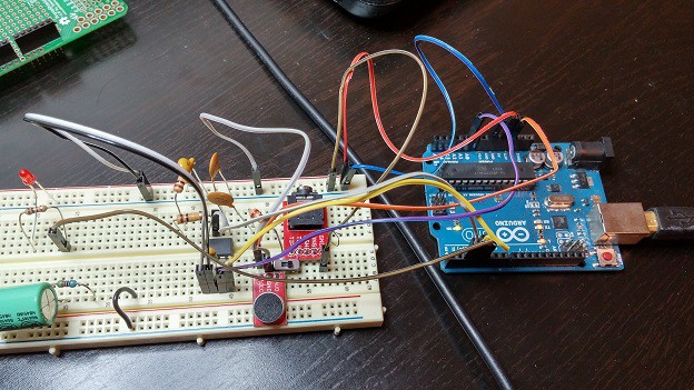
10/05/2015 at 02:33 • 0 commentsThe first circuit I built made full use of the analyzer chip. This EE Times article was very helpful during initial construction, and I used a lot of this code for early debugging.
![]()
![]()
Reading input directly from the chip proved the circuit worked and the microphone seems to be picking up sound at a reasonable difference.
I connected a single LED and mapped to one of the frequencies. When that frequency hits a threshold the LED lights. I don't know why, but that single light flashing along with the music (Spoon's "I Turn My Camera On") is funny to me. But overall the circuit works and most importantly it proved that there is no delay between reading the signal and outputting a signal.
The next step was ordering all of the parts and building out the circuit. The code i used is below. Significant credit to Max Maxfield.
/* Test #2 adds LEDs for visual representation */ // MSGEQ7 bands = 63Hz, 160Hz, 400Hz, 1,000Hz, 2,500Hz, 6,250Hz, 16,000Hz int ctrlReset = 2; // Digital pin 2 = signal to reset MSGEQ7s int ctrlStrobe = 3; // Digital pin 3 = signal to strobe (read data from) MSGEQ7s int channelLeft = A0; // Analog pin 0 = spectrum data from left channel //int channelRight = 1; // Analog pin 1 = spectrum data from right channel int spectrumLeft[7]; // Array to store 7 bands of spectrum data from left channel //int spectrumRight[7]; // Array to store 7 bands of spectrum data from right channel int Led4 = 4; //LED to light up and test 1 band void setup() { Serial.begin(9600); pinMode(ctrlReset,OUTPUT); // Define reset as output pinMode(ctrlStrobe,OUTPUT); // Define strobe as output pinMode(Led4,OUTPUT); digitalWrite(ctrlReset,LOW); // Pull the reset signal low digitalWrite(ctrlStrobe,HIGH); // Drive the strobe signal high digitalWrite(Led4,LOW); } void loop() { readMSGEQ7(); // Display values from the left channel on the serial monitor for (int i = 0; i < 7; i++) { if (spectrumLeft[i] < 100) Serial.print(" "); if (spectrumLeft[i] < 10) Serial.print(" "); Serial.print(spectrumLeft[i]); Serial.print(" "); } Serial.print(" "); /* // Display values from the right channel on the serial monitor for (int i = 0; i < 7; i++) { if (spectrumRight[i] < 100) Serial.print(" "); if (spectrumRight[i] < 10) Serial.print(" "); Serial.print(spectrumRight[i]); Serial.print(" "); } */ Serial.println(); if (spectrumLeft[4] > 100) digitalWrite(Led4,HIGH); else digitalWrite(Led4,LOW); } void readMSGEQ7() // Read the seven spectrum bands from the MSGEQ7 chips { digitalWrite(ctrlReset, HIGH); // Pulse the reset signal, which causes digitalWrite(ctrlReset, LOW); // the MSGEQ7s to latch the spectrum values delayMicroseconds(75); // Delay to meet minimum reset-to-strobe time for(int i=0; i <7; i++) // Cycle through the 7 spectrum bands { digitalWrite(ctrlStrobe,LOW); // Read current band (then increment to next band) delayMicroseconds(40); // Wait for outputs to settle spectrumLeft[i] = analogRead(channelLeft) / 4; // Store current values from left & right channels // spectrumRight[i] = analogRead(channelRight) / 4; // Divide 0-1023 by 4 to give 0-255 //Dividing by 4 is really for PWM output and I can probably eliminate that later digitalWrite(ctrlStrobe,HIGH); delayMicroseconds(40); // Delay to meet minimum strobe-to-strobe time } } /* * Copyright (c) 2014 Clive "Max" Maxfield * * Permission is hereby granted, free of charge, to any person obtaining a copy * of this software and associated documentation files (the "Software"), to deal * in the Software without restriction, including without limitation the rights * to use, copy, modify, merge, publish, distribute, sublicense, and/or sell * copies of the Software, and to permit persons to whom the Software is * furnished to do so, subject to the following conditions: * * The above copyright notice and this permission notice shall be included in * all copies or substantial portions of the Software. * * THE SOFTWARE IS PROVIDED "AS IS", WITHOUT WARRANTY OF ANY KIND, EXPRESS OR * IMPLIED, INCLUDING BUT NOT LIMITED TO THE WARRANTIES OF MERCHANTABILITY, * FITNESS FOR A PARTICULAR PURPOSE AND NONINFRINGEMENT. IN NO EVENT SHALL THE * AUTHOR(S) OR COPYRIGHT HOLDER(S) BE LIABLE FOR ANY CLAIM, DAMAGES OR OTHER * LIABILITY, WHETHER IN AN ACTION OF CONTRACT, TORT OR OTHERWISE, ARISING FROM, * OUT OF OR IN CONNECTION WITH THE SOFTWARE OR THE USE OR OTHER DEALINGS IN * THE SOFTWARE. */ -
Initial Concept
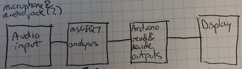
10/03/2015 at 20:53 • 0 commentsThe overall idea for the project was to have a series of lights around a top hat to display whatever sound was happening in the room. The top of the hat would be used for all electronics. Adafruit's NeoPixels would be ideal, but can also get expensive quickly.One of my biggest concerns was being able to process the audio signal quickly enough and display it with an appropriate refresh rate. The answer to my questions came int he form of the MSGEQ7 graphic equalizer display filter. This wonderful bit of hardware takes a single channel audio input and converts it to a DC signal displaying 7 frequency bands. Sparkfun has since re-released their Spectrum Shield, which would have saved some significant effort, but this was a good build nonetheless.
I was also concerned about the quality of the microphone, especially since nobody would be talking directly into it. The electret microphone breakout from Sparkfun ended up working well.
In general, the flow would be:
![]()