-
Open Source rules!
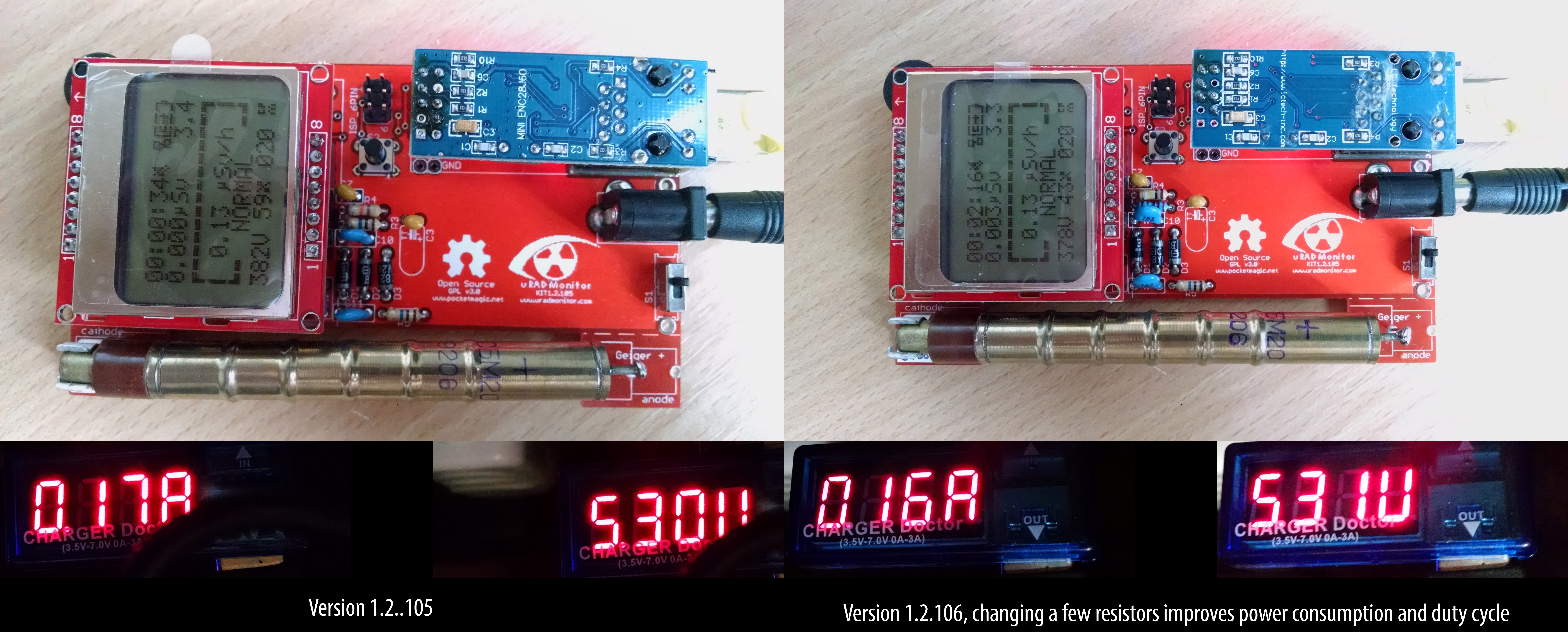
08/05/2017 at 21:54 • 0 commentsHi just finished fixing a list of about 15 issues on github. This resulted in a new firmware version update and a new hardware iteration - minor with just a few values of some resistors changed. One of these was particularly interesting.
As discussed with @Ted Huntington via the comments the other day, the high voltage inverter in these units jumps from 3.3V input to a configurable output voltage that is now set to 380V to fit the SBM-20 Geiger tube. To achieve this long jump, some components are critical to the design, such as the MPSA42 transistor and the 2.2mH inductor. For the latter, some of those building this circuit were having some issues, not being able to obtain the target voltage, or in some cases needing to change (lower) the inductor frequency to get the last push to the target. I did my best to indicate the right sources for the inductors, but in some cases this was not enough.
So what happened with the github issues? Well Wolferl1 pointed out some issues with the values I've been using. And indeed, he was right. I changed those right away, and this brought some immediate improvements, such as lower PWM duty cycle to the high voltage inverter, and lower power consumption:
![]()
But the lower duty cycle gives more margin to the inductor working interval, lowering the criticality of this component. His suggestions went further like using a 47M resistor in the high voltage divider circuit used for feedback, but I decided to go with more common components.
Yet, another example of team work, making this product better. Open source rules!
-
Going for CE-rtifications
08/05/2017 at 11:12 • 0 commentsThis project addresses mostly DIY enthusiasts and IOT fans, however I felt it reached a point where it is mature. That's because it got everything one HW product could possible want: multiple iterations, community support, community new features and new code and a high number of units distributed across the globe.
![]()
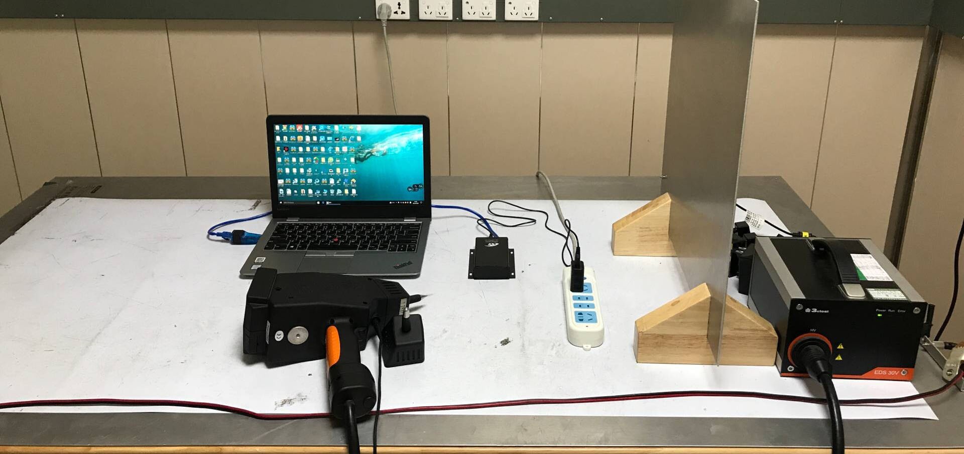
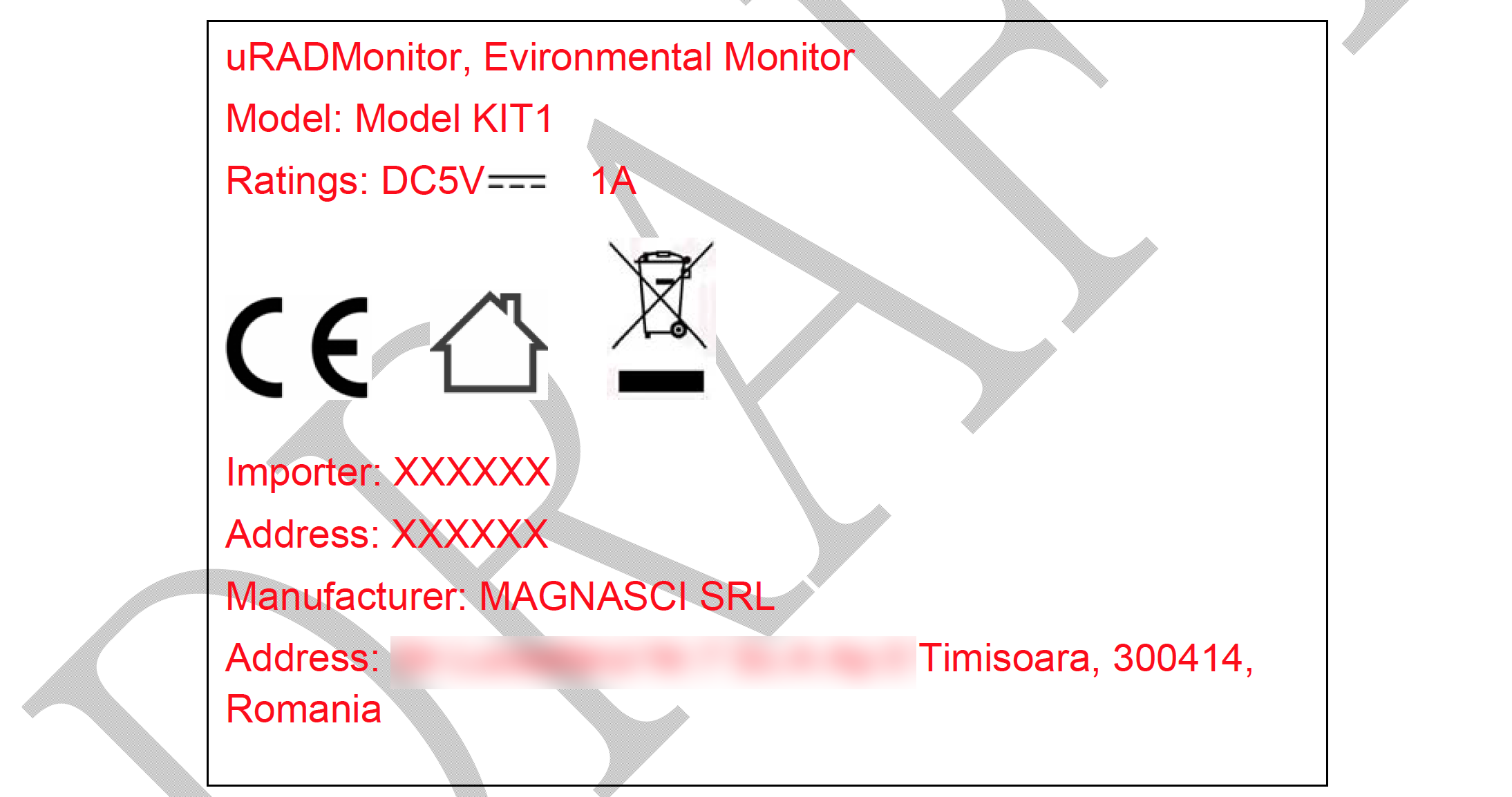
It was time to add one missing thing to complete the work and that is certifications. First I wanted was CE, offering extra trust to what this product is. So I started researching ways of accomplishing the CE tests with minimum costs. I was able to identify a company, discussions went well, I send them the payment and the documentation and things started to move.
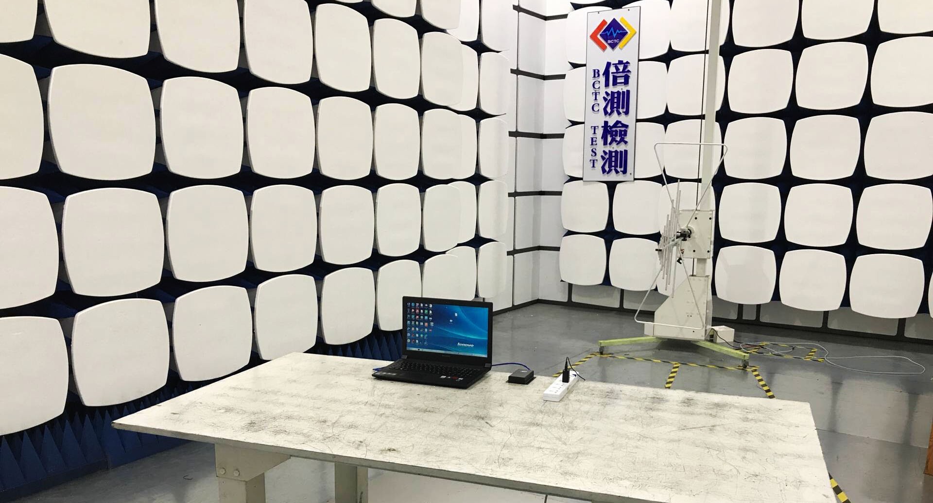
What they did was a large number of tests to verify literally everything, from drop tests to EM interferences.
![]()
![]()
In the end I got the "TEST PASS" label, together with hundreds of pages of reports, documenting every technical aspect of the device and of the test, probably more then I knew about the device I designed. The company I used was BCTC in Shenzhen, and I am very happy with their professionalism and promptitude.
![]() Mission accomplished.
Mission accomplished. -
KIT1 iterations
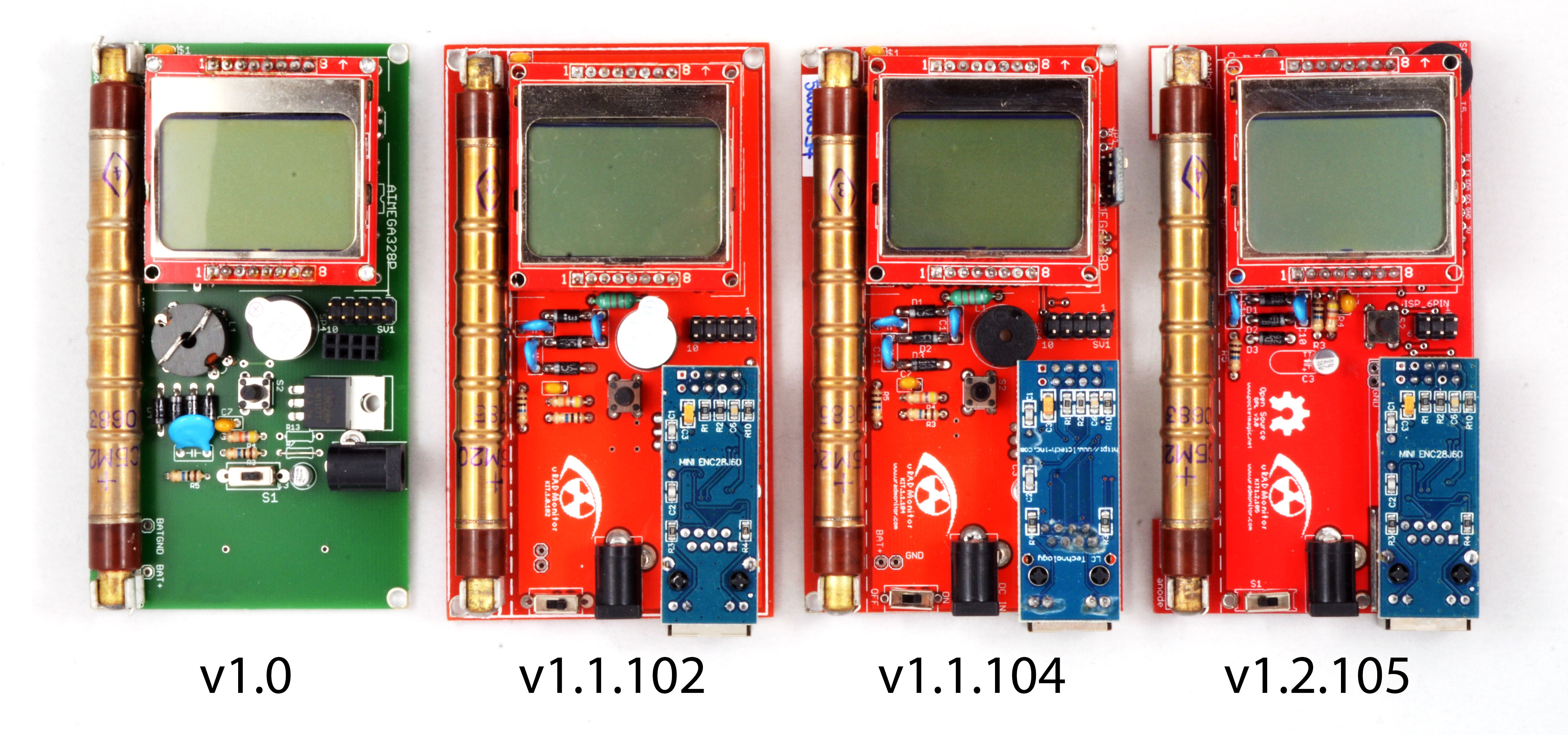
05/11/2017 at 16:33 • 4 commentsDeveloping the KIT1 raised several problems in hardware and software, and those were solved with multiple PCB iterations.
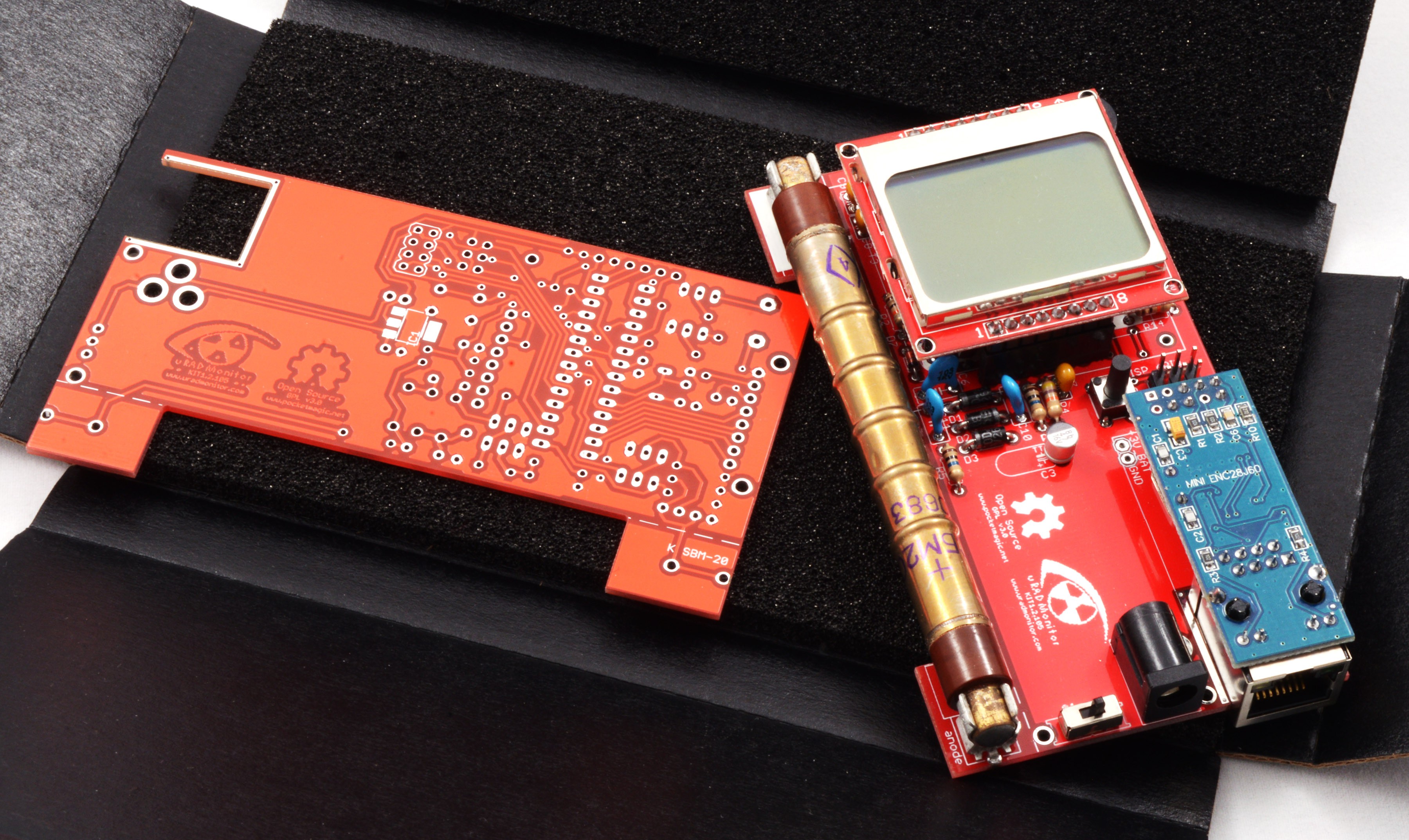
![]()
These are just of the few that were built. Initially, v1.0 used a ferrite transformer for the High Voltage inverter needed to boost the 3V Vcc up to 400V required by the Geiger tube. Making such a transformer was a difficult task, that would limit the production capabilities. The secondary needed about 400 turns of very thin wire:
![]()
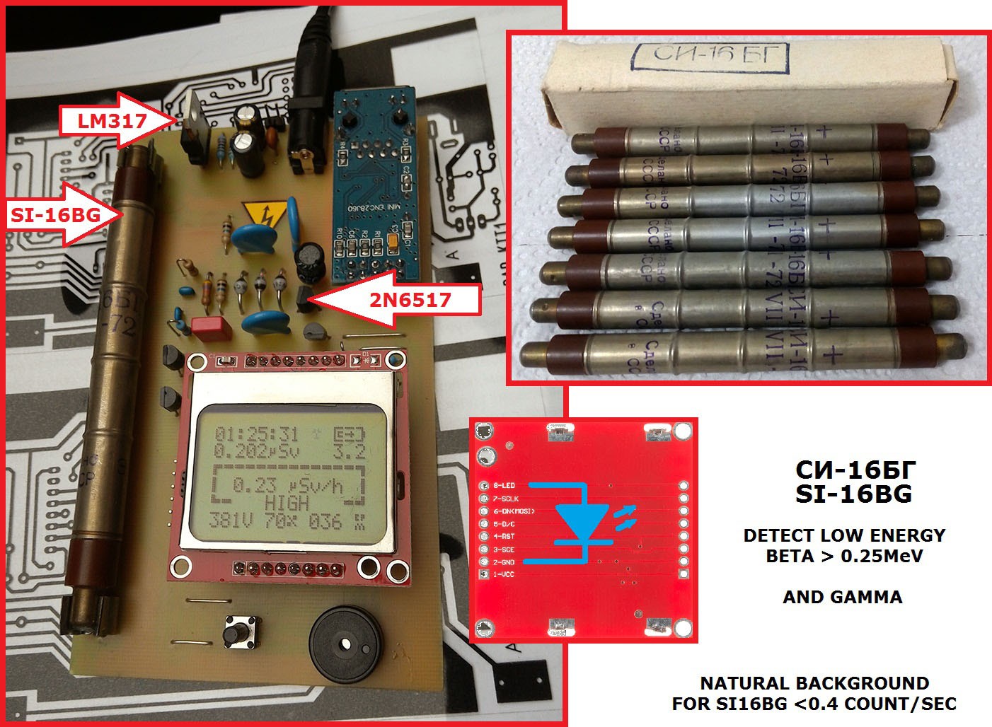
This was the most important change in the 1.1 versions, replacing the ferrite transformer with a simple inductor readily available in electronics shops. A voltage multiplier would compensate for the lower voltage of the new inverter, so we would still reach the 400V target needed by the Geiger tube. The switching transistor is blocked with a second PNP transistor to collapse the magnetic field on the coil faster, and generate higher voltage spikes. More on the development of a compact high voltage inverter here. This approach was used in the uRADMonitor model A as well, just with SMD components.
Version 1.1.103 is not visible in the first picture, but you can see it below. 103 was supplied after the successful indieGogo campaign in 2016, both as a solderable KITs and a readily assembled units.
![]()
1.1.104 brings an extension port, used to connect additional sensors. The Repository on GITHUB offers default code with a driver for the Bosch BME280 sensor included by default.
1.2.105 is a new kind of beast. The board has been reworked, the speaker and central button were moved, the PCB under the tube has a milling layer to avoid any interferences on the radiation detection capabilities, and the ISP connector went from the redundant 10pin variant to the 6pin standard.
![]()
The extension port outputs voltage, I2C and UART connections to the microcontroller. You can use it for virtually any kind of sensor using these protocols, like PM2.5 sensors, UV sensors and so on.
The GitHUB code comes with a dynamic ID allocation system, that means the units can join the uradmonitor network automatically.
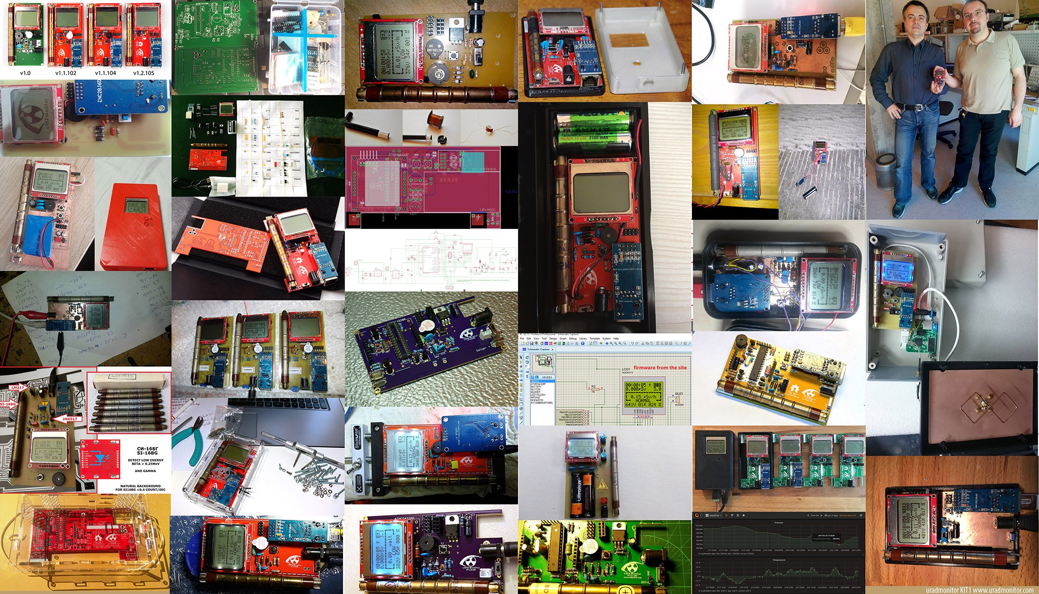
Community variants
I already presented the advantages of the community support for this open source design in the previous logs. The KIT1 development took advantage of the creative effort of many makers out there.
Here are some pictures showing a few of them:
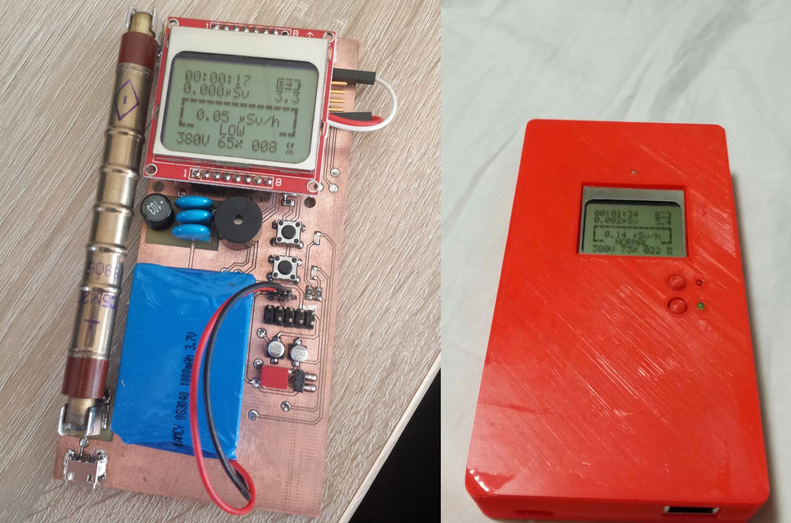
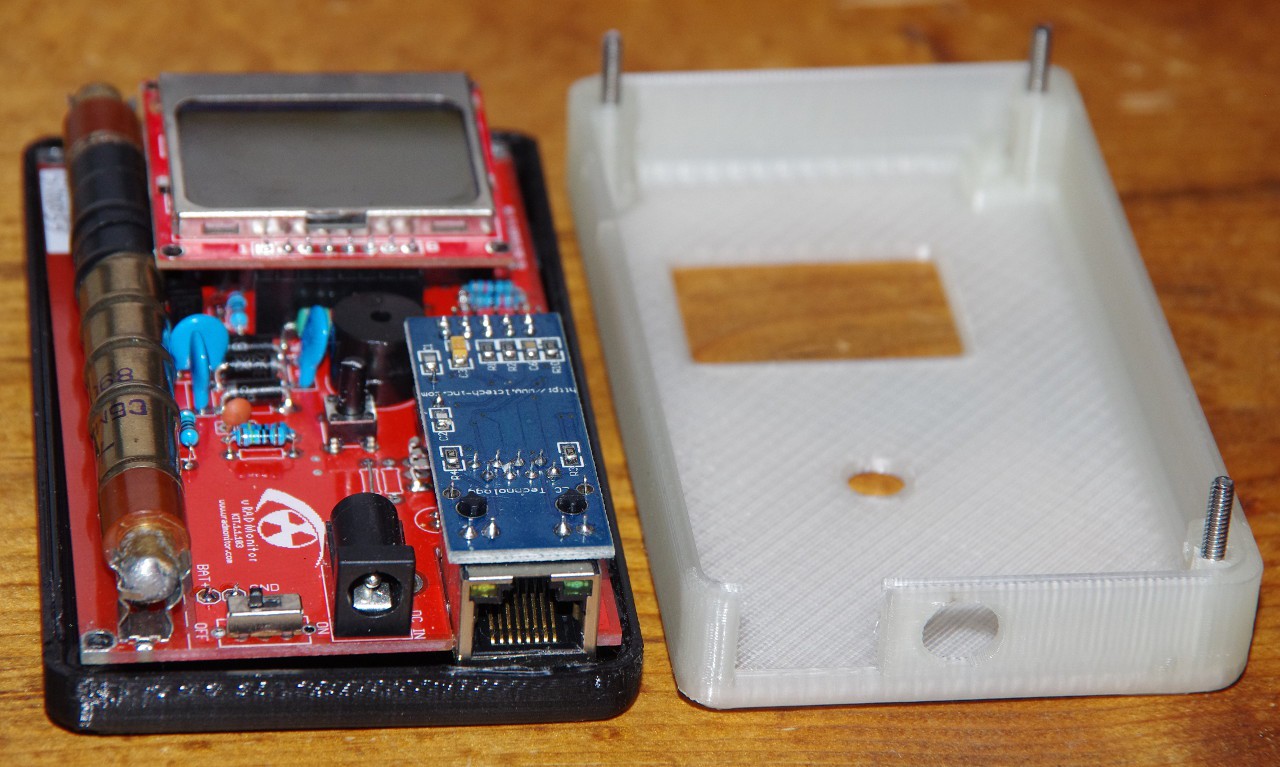
Chris and Frederik built a SMD variant, with a LIPO adapter to make the KIT1 fully portable. They also did a 3D printable enclosure:
![]()
![]()
![]()
Otakar built his from scratch, using version 1.1.103 design files:
![]()
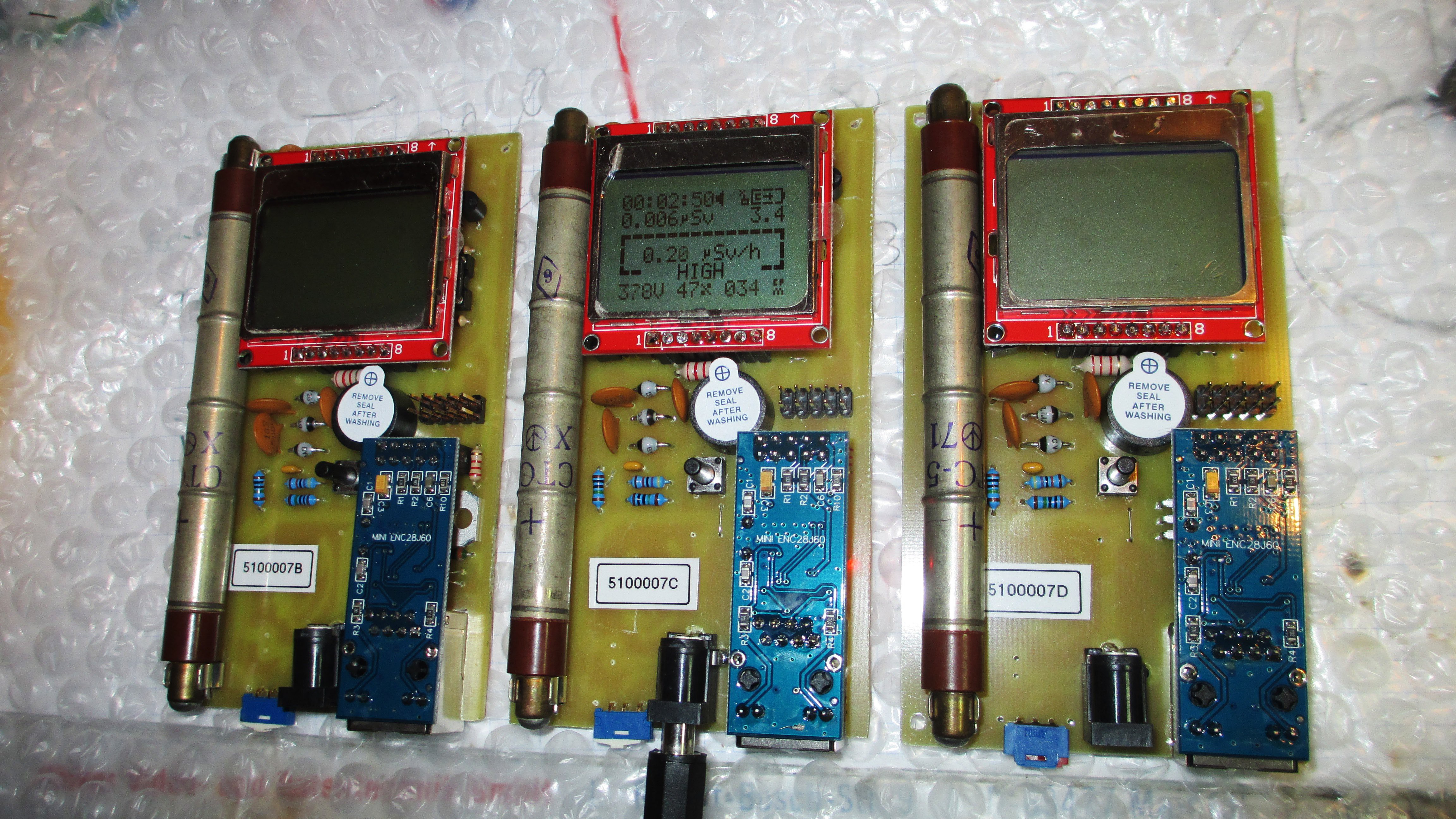
Tino, did an amazing job building 3 units from scratch:
Adrian used the excellent @oshpark services for his KIT1 unit which came out nicely:
![]()
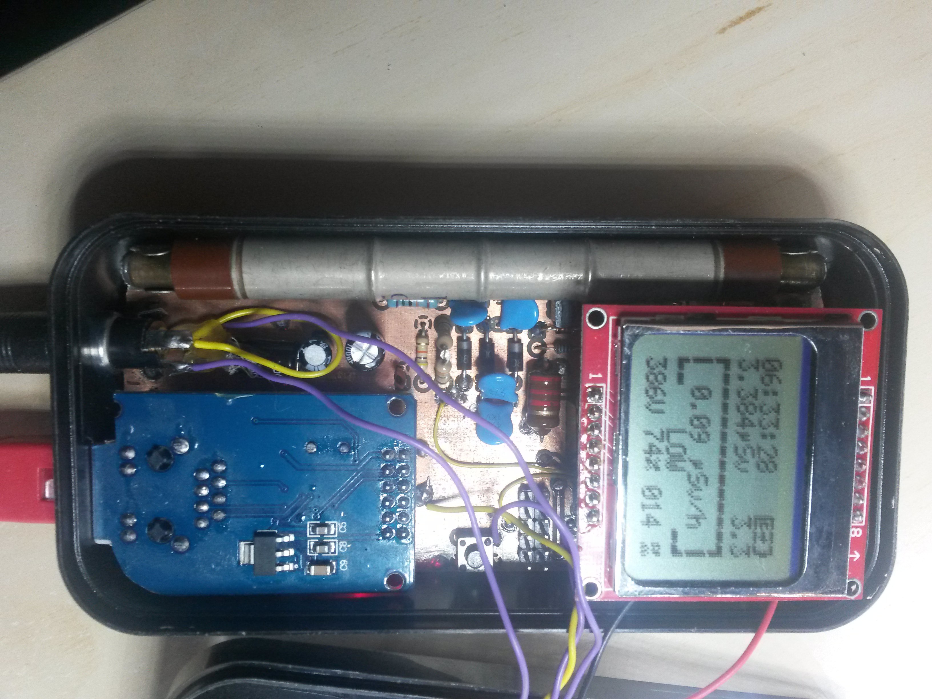
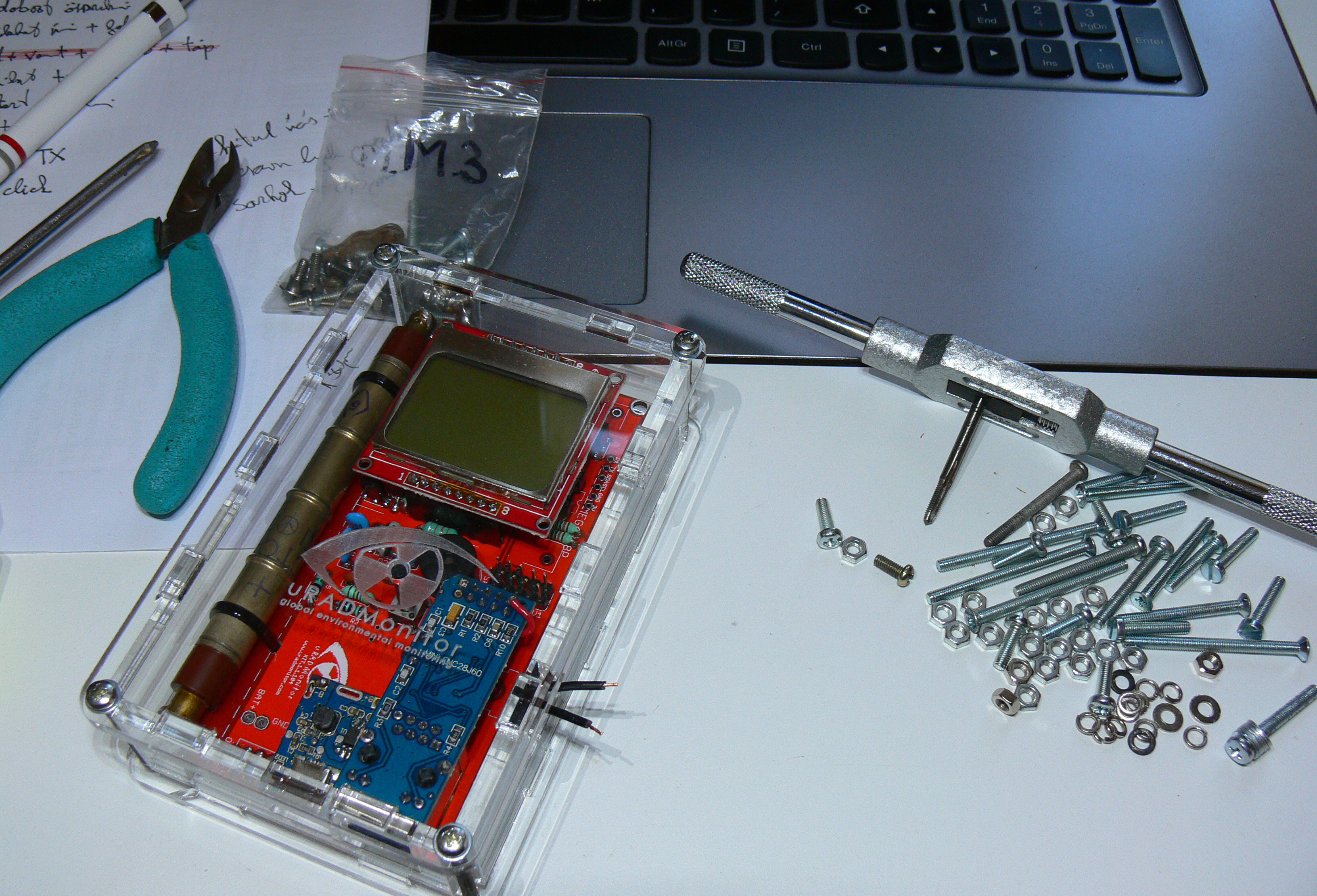
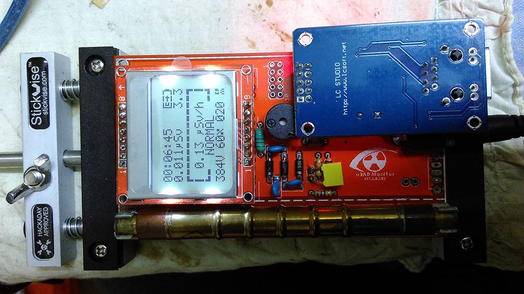
Here's an interesting, highly customised KIT1 version:
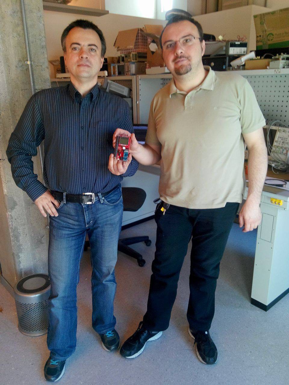
![]() Here's Horia and Fabio, good friends from the 4HV.org forum, with their fresh new KIT1, ready to take some of Fabio's X-RAY experiments:
Here's Horia and Fabio, good friends from the 4HV.org forum, with their fresh new KIT1, ready to take some of Fabio's X-RAY experiments:![]()
Malte built the new 1.2.105 on a beautiful orange PCB. Need to ask him where did he order it from. He also use a big fat inductor, that really can't go unnoticed:
Here's another one from Nicolas, including a custom enclosure:
![]()
Some simulations of the circuit and firmware some other guys were doing:
![]()
Sulley's unit running on 2 AA batteries (like originally planned):
![]() And the masterpiece created by Akos, that you saw in one of the previous project logs:
And the masterpiece created by Akos, that you saw in one of the previous project logs:![]()
Here's another KIT1 built from scratch, most likely using toner transfer:
![]()
Hori's LiPO solution:
![]()
One beautiful 3D Printable enclosure, available on Thingiverse:
@Kumar, Abhishek's unit, still hoping he will connect it to the Internet someday:![]()
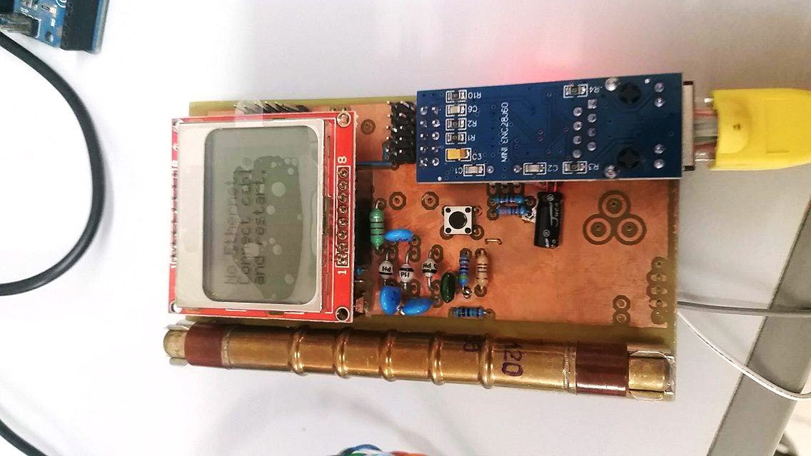
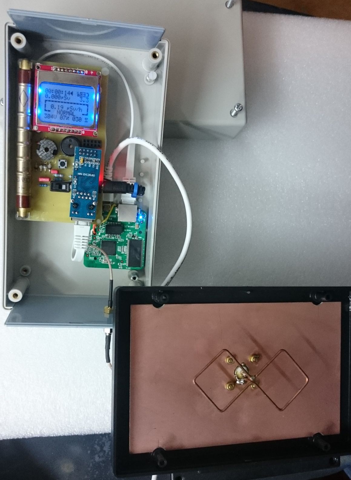
And who said the KIT1 can't talk wireless? The design is made for the ENC28J60, but this clever maker found a solution to connect to it's wireless router via the waves:![]()
![]()
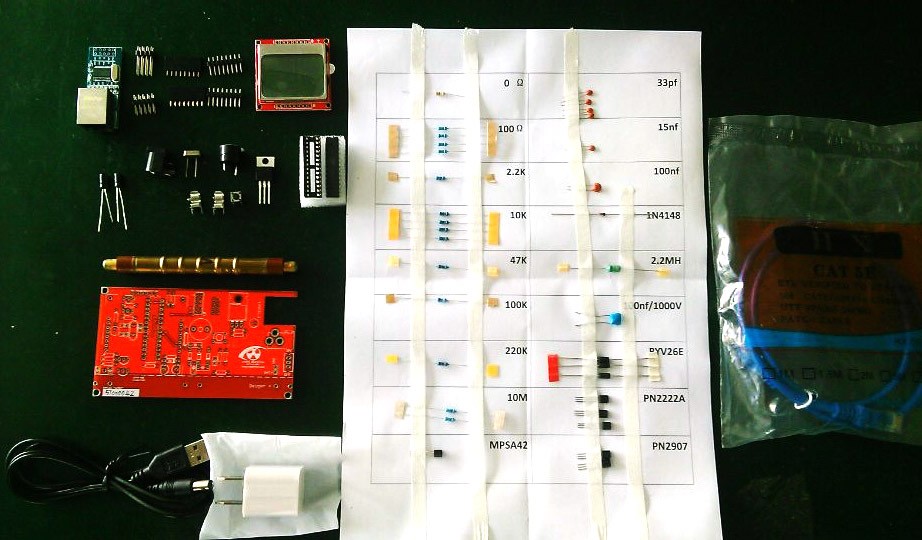
Tempted to build yours? I surely hope so! The latest design is available on Github. It will only take you a few hours to do a toner transfer PCB and have some fun soldering this versatile IOT device:
![]() You'll find the complete code there as well, or you can use this direct link. More information is available on the uRADMonitor blog, or you can see what other KIT1 builders posted on the forum.
You'll find the complete code there as well, or you can use this direct link. More information is available on the uRADMonitor blog, or you can see what other KIT1 builders posted on the forum. -
Open Source uRADMonitor KIT1
05/11/2017 at 15:05 • 0 comments![]()
Open Source means collaborative work, joined effort leading to extraordinary things. Recently we saw how a talented maker from Oradea, Romaniapushed his KIT1 #uradmonitor unit to the limit!
![uradmonitor_kit1_custom]()
He used a lot of his personal time to build and document something better than the original. In the end he asked for nothing except to get access to the entire KIT1 source code so it can be improved further by the community of makers. We got the message and decided to act.The server infrastructure
uRADMonitor is Big Data. Hundreds of detectors worldwide are collecting measurements every minute, and the server deals with millions of entries in its database every day. The database holding KIT1 data was designed for efficiency: only the minimum data goes in. One reason for open sourcing was to allow customising the KIT1 units with additional sensors. We had to adapt the server backend in this regards, and now there’s an expandable list of parameters that can be uploaded.
Then there’s the data accuracy which needs to be guaranteed to a reasonable degree by supervising and testing the hardware, something impossible with open, remote constructions. Making the server decide if the data is genuine or just some random useless bits was not an easy task.
Last but not least, here comes the security. Initially, open source can be a source of vulnerabilities of the exposed system. We had to make sure the new open communication protocol is safe to use. We’ve implemented API Authorisation for all data uploads generated by the Open Source KIT1 units. Go to the dashboard, and create an account if you don’t have one already. You’ll need to use the user-id and the user-key listed there with your new uRADMonitor KIT1. If you go for the stock firmware, then you won’t need them.Please welcome the Open Source uRADMonitor KIT1
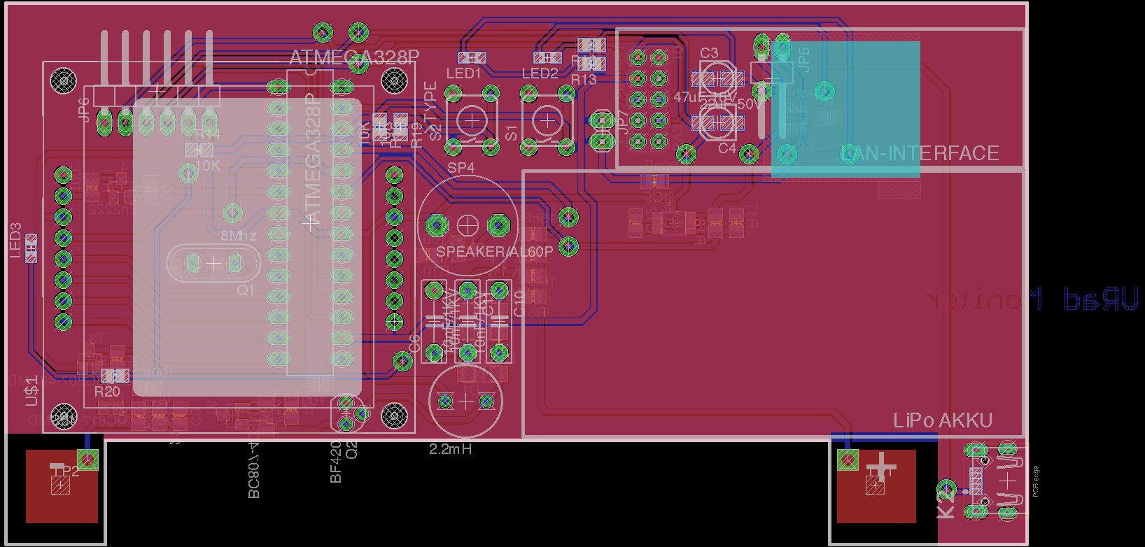
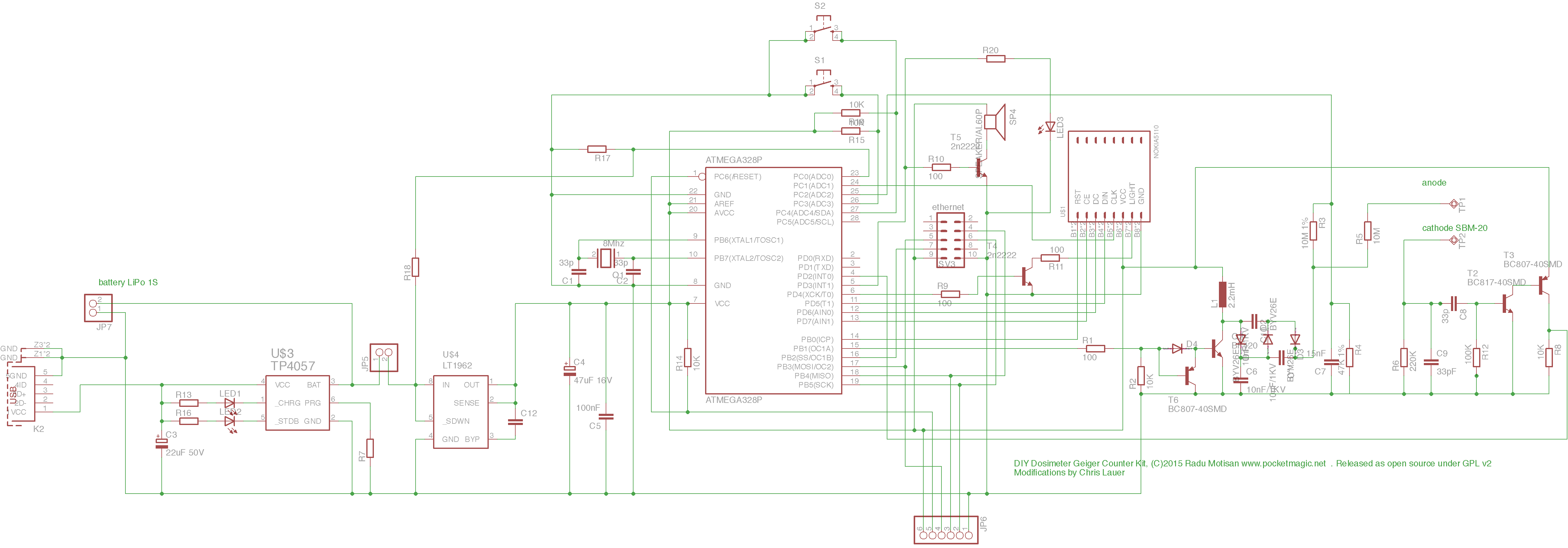
With so many changes on the server backend, we had to improve the KIT1 circuit and PCB. We tried to add many of the suggestions received on the forum. From now on however, feel free to fork the original Github repository and do whatever you like with this open design. The new version is KIT1.2.105, and you can see the first design images below:
![open_source_uradmonitor_kit_105_sch]()
![pcb_opensource_kit_105_pcb]()
The new design is more compact, so if you want to add a battery you’ll have more space. The arrangement of some components has been optimised and the regulator becomes the single SMD component on this otherwise exclusively through hole components PCB. As soon as we get the first of the new PCBs, we’ll add more pictures with them.Using the KIT1.2
Once your KIT1.2 circuit is complete, download the firmware code from Github. In config.h add your user-id and user-key from the dashboard.
![uradmonitor_kit1_config]()
Compile the code, and write the HEX to your board, using a 6 PIN ISP connector. For the fuse settings, if you followed the original design, you’ll need to set the external 8MHz crystal, and make sure the EESAVE fusebit is set.avrdude -p atmega328p -c usbasp -U lfuse:w:0xDC:m -U hfuse:w:0xD7:m avrdude -p atmega328p -c usbasp -U flash:w:uradmonitor-KIT1-EXP.hex:i
Your unit will receive a device ID allocated dynamically by the server. If you want to use a BME280 sensor, there is code already in place. Just make sure the USE_BME280_SENSOR is set in the config file.
Adding more sensors
With the extension port that exposes I2C, UART and power, you have the possibility to add a large number of additional sensors. Add the sensor driver code, and do the sensor reading in app/data.cpp and app/data.h initSensors() and readSensorsSlow(). To send the data online, see the code file misc/expProtocol.h for parameter IDs and how they are used in uRADMonitor.cpp line 350. More parameter IDs will be added based on demand. All previous KIT1 hardware versions are compatible with the new firmware. For any questions and assistance, use the forum.
To compile the code, please use Eclipse and the AVR Crosspack plugin as well as the AVRDude software. For uploading the HEX code, you can use the versatile usbAsp programmer configured for 3.3V!License
uRADMonitor KIT1 is released under GPL v3 or newer. Read the license terms here. For custom licensing, contact us.
Download PCB layout, Gerber files and firmware source code here. -
Building the KIT1 with extra features
05/11/2017 at 15:04 • 0 commentsAs the KIT1 is open source, talented community makers often brought upgrades to this versatile IOT platform. Here' the work of Akos, that adapted the KIT for battery use and also built a plexiglass enclosure.
![]()
Last week I’ve assembled a KIT1 and posted some details about it to the forum. radhoo praised the article and asked me to share it on this blog, maybe will be helpful for the readers. So, here is an updated “copy-paste” from the original post.
The diy kit is based on the v1.1.104 pcb. It was made with minor modifications / improvements regarding the original model. First of all, I’m a beginner in all this electronics and coding stuff, so if I wrote something stupid, please correct me. I’m always open for constructive criticism. Second, sorry for my English, it is not my native language.Differences to the original KIT1
– Incorporated lithium battery
– Builtin battery charger module + micro usb port
– Low dropout (0.17v) regulator
– Real PoE connectivity, no additional cable / connector needed on the device side, just the rj45 connector
– Transparent case made from plexiglass
Updated BOM, with the components I used (if something is missing, please let me know).
Note: I bought the components for these kits from local stores, the best available quality. Hence, the visual aspect of these components may differ from the originals shipped with the KIT1. I measured / tested all of them before soldering, to make sure everything is up to the specs.![03_portable_unit]()
I built 2 kits: one for me and on for a friend. He asked to make it portable, because he will use it mainly on field, as a mobile unit, outdoors and on industrial working sites. This raised two challenges:
The final product has to have a:
– reliable and high capacity rechargeable battery
– a robust but not too bulky case
Regarding the pcbs, after some emails, radhoo was so kind to send me 2 pieces, thank you again! And because i didn’t want to ‘destroy’ these beauties, all the modifications are made without hacking the pcb!Power supply / charger / power consumption
Nowadays the “standard” power supply for handheld devices is the type b micro usb port. You can find them virtually anywhere. Also, it is fairly easy (and very cheap) to implement them into DIY stuff, using these modules. To add these without modifying the pcb, I simply glued them with 10 minutes epoxy. Not too smart, but will surely withstand the abuse of the backlash from the usb cable.
As for the battery, probably everybody has access to some broken smartphones… although the phone or display is broken, chances are good that the battery is still functional. You just have to hook up to the output of the charging module and the input of the voltage stabiliser and it is ready to use. I’ve used one scavenged element from an old macbook battery. It contains 4 lithium cells, similar to the one on this site. The cells are roughly the size of the kit1 pcb. This way, I saved all costs on charger + battery (0.3 euro).![filtering-2]() To keep a safe distance between the aluminum foil of the battery and the bottom of the pcb (high voltage!), I used 4 self adhesive rubber shoes, like those intended for furniture.
To keep a safe distance between the aluminum foil of the battery and the bottom of the pcb (high voltage!), I used 4 self adhesive rubber shoes, like those intended for furniture.
Most lithium batteries have a nominal voltage of 3.6V (min 2.9V, max 4.2V). The recommended operating voltage for the KIT1 is min 3.0V, max 3.3V. To use the battery to the maximum, I opted for a 3.0V voltage regulator. It has to have ultra low dropout voltage, in order to maximize battery life.
I also had to replace the original lm1117 voltage stabiliser, because it has a large dropout voltage, 1.1v. (this would be: 3.0 + 1.1 = 4.1v, maybe just 5% of the overall battery capacity. Not suited for my case … ).
After a lot of research, I bought the MCP1700-3002E/TO regulator. It has a very low dropout, only 0.17V! We get: 3.0 + 0.17 = 3.17v, so I can use around 95% battery capacity. So far, so good.
The max output current for the MCP1700 is 250mA, and the max input voltage is 6.0V. As the lithium battery never goes above 4.2v, it’s ok for me.
My battery is quite old and tired, and so the 3700mA nominal capacity was irrelevant. To estimate the battery life, I’ve made some measurements. The kit1 has the following current consumption @ 3.0V (*):
Offline mode, backlight off: 36mA
Backlight: 18mA
Online mode, backlight off: 147mA
Maximum peak current: 170mA
*with the red led desoldered from the ethernet module.In online mode, with fully charged battery (4.2v) it took ~18 hours to discharge it to 2.9v. Discharging a lithium cell under 2.9v is not recommended, so even if the KIT1 kept working at 2.9V, I stopped the measurement. It then took ~5 hours to fully charge the battery (from an USB port). Based on the above current consumption scenarios and the measured 18 hours, it is fairly safe to estimate 50 hours uptime in offline mode. more than adequate for daily use on the field.
![mcp1700]()
This regulator has a different pinout, then the original 1117. I had to make a tricky implementation, but that worked.
At the moment, the only flaw is, that the KIT1 keeps working even under 2.7V, over-discharging the battery. In the long run this will damage the lithium cell so the firmware should be modified to post a ‘low battery’ message to the screen and standby the unit, if the voltage drops below 2.85V. (We need access to the full source code to implement this)
Also, it would be nice to have a voltage divider on the battery terminals (say 4.2V to 3.0V) and implement a battery voltage monitoring function in the firmware. This way the user can have a feedback about the battery state. There are 2 unused analog pins on the mcu, this shouldn’t be a problem.![filtering]() The MCP1700 needs 2 filtering capacitors to work properly. I’ve just replaced the original c3 with 1uf ceramic, the other one (Cout) was soldered on the back side of the pcb
The MCP1700 needs 2 filtering capacitors to work properly. I’ve just replaced the original c3 with 1uf ceramic, the other one (Cout) was soldered on the back side of the pcb![p1120015]()
![switch]()
Because the charger module covered some holes of the on / off switch on the pcb, I’ve used a different switch, placed on the right side of my case.Real PoE
For the stationary unit installed outside, I wanted to have just one single cable (for supply + ethernet). According to wikipedia, the POE standard uses 2 modes: A and B. Unfortunately after some fiddling, I’ve realised that none of these modes are implemented in the hr911105a RJ45 connector, used on the enc28j60 ethernet modules. What a pity! All the 8 pins are galvanically isolated. I needed access to pins 4+5 for dc+, respectively pins 7+8 for dc-
![poe-cable]()
Custom made ethernet cable: on the router end there is an additional USB cable, serving to inject 5V dc. This will be powered from the unused USB port on my router. The other end is just a standard RJ45 connector.Hacking the rj45
It is possible to open the metal sheet on the connector.
![10_rj45-open-1]()
The isolation transformers from rx and tx are clearly visible:![11_rj45-open-2]()
Then I’ve removed some plastic with a red-hot cutter blade, to expose the pins. Cleaning and soldering the wires to the selected pins was relatively easy:![12_rj45-open-with-cables]()
For tapping I’ve removed one of the lateral side tins. After putting some patches of insulating tape to the exposed pins I closed the connector.![13_rj45-closed-with-cables]()
The terminal wires (green + white) were soldered to the appropriate INPUT pins (+5v and gnd) on the micro usb charger module. Now i have a real poe module!
Attention: do not solder the +5V cable to the charger module OUTPUT, because it will overcharge the lithium battery! Lithium batteries, if charged beyond 4.3V can explode or catch fire!![short]()
This modification doesn’t deal with the two 75 ohm resistors, which kinda “shorts” the usb port. But if you do the math: 2 x 75R = 150R. For 5V / 150R = 33mA extra current consumption for the usb port. The usb port standard specifies at least 500mA / port. The whole device does not absorb more than 200 mA, so I think this is on the safe side.
Regarding the heat production on the two 75 ohm resistors:
0.033A x 5v = 0,166W total. There are 2 resistors, so this is 0.083W / resistor. Even if the resistors will burn out, I do not care, they are useless in this configuration (I think).Note: using 5V DC with poe is not recommended on long cable runs because when load is applied, the voltage drops quickly. In my case, I needed only 5m of ethernet cable. With the device connected, the 5V dropped to 4.3V. This means, that the charger module will output max 4.0 volts, so the battery will be never charged to 100%. This is not a problem for me, as the router will continuously supply the power. However, for much longer cables, one should consider using an adjustable dc to dc booster between the USB port and ethernet cable (on the router end), to compensate for the voltage drop. With the uradmonitor unit turned on, clip a voltmeter to the charger module input pins, and adjust the booster on the router side, until exactly 5.0v is measured by the voltmeter. This way the voltage is compensated for the respective cable. If you alter the cable length, you have to re-do the adjustment!
Additional sensors – bme280
![bme280]()
The v1.1.104 pcb has a nice feature, the extension port. This can accept any module with serial or i2c interface. Although, it is possible to retrofit any older kit with additional sensors – soldering the wires directly to the mcu pins, this breakout port is a more elegant solution. I’ve populated this with a bme280module. You can buy one here.
These sensors are very high quality and one can obtain a lots of info, with proper code implementation:
– temperature
– pressure
– altitude (uncalibrated)
– relative humidity
– dew point
– heat index (shadow)
– heat index (sunlight)
Attention: during operation the sensor chip is sensitive to light, which can influence the accuracy of the measurement! The position of the vent hole minimizes the light exposure of the sensor chip. Nevertheless, BOSCH recommends avoiding the exposure of BME280 to strong light. Probably it would be a good idea to paint black the sensor area inside the case… I always suspected that nail polish has some utility 🙂
I wrote a small arduino sketch to display all these values, using the SparkFunBME280 library.![16_uradmonitor_kit1_with_bme280_sensor]()
Unfortunately, at the time of writing this article, the uradmonitor source code (v117) is not fully open. We have to wait for radhoo to implement this sensor, or much better, to publish the full source code on github.Case design
![17_uradmonitor_kit1_plexi_enclosure]()
For the device to be fully usable outdoors and to have a better visual experience, it needs a case. I’ve designed the case in corel draw x8, made two very similar models, one for wall mounted fix station, one for portable device. Despite my very limited knowledge in Corel, I managed to finish it with quite good results. It was then laser cut from 3mm clear plexiglass.![case-draw]()
Since the enc28j60 chip produces a lot of heat, in a closed case this would deteriorate the temperature readings. I’m interested in the REAL outdoor readings. If the temperature value is not correct, all the other values are useless. The humidity calculation formula is also based on temperature. Accordingly, I had to assure a very good ventilation for the sensor:![p1120008]()
So, here are lots of ventilation holes on strategic parts of the case. These are circles 1.5mm in diameter – the smallest diameter the laser can cut (?), without melting too much plexi around. I hope the insects will not pass these holes. They will surely try. When winter is coming, a ‘heated’ hotel is very tempting…
As hot air always goes up, the components arrangement is not very fortunate for the sensor, since it is placed exactly above the biggest heat source in the kit1. I decided to mount the whole device upside down to the wall, this way the bme280 will be under the ethernet module. The ventilation holes should produce a chimney effect*, that will take care to transport the air from bottom to top. Theoretically, the sensor will always receive the unheated air from outside, obtaining correct readings. While used as a fixed station, the micro usb port will be out of order. Hence, it will be covered with a cap, to keep the bugs at bay.
* I will test this theory when the device will be mounted on the wall, placing an external temperature sensor near the case, and compare the 2 values.
If anyone is interested to build this case, here are the corel draw x8 files: fixed station with bme sensor, portable, without bme sensor.If you have any additional ideas how to upgrade the case, you are free to modify, but please share here!
![p1110998]()
I will add new photos when it will be installed in its final place. For high resolution pictures you can visit my album.![case-id]()
Thank you Radu for all the big effort and helpful attitude in this worldwide project!Thanks for reading,
wanek t.
-
getting the KIT on HaD
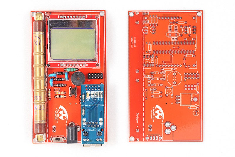
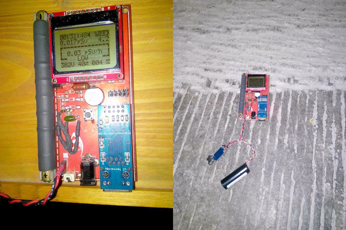
10/04/2015 at 18:11 • 0 commentsThis is probably the easiest way one can take to have a good digital radiation dosimeters. It was built for the SBM20 Geiger tube, widely available at reasonable prices. Alternatively, other tubes can be used and the PCB has been designed to fit various tubes. The high voltage inverter can also go as high as 600V, to accommodate any custom tubes. The version currently posted on HaD is the latest, the KIT 1.1 and brings several improvements as presented in the project description.
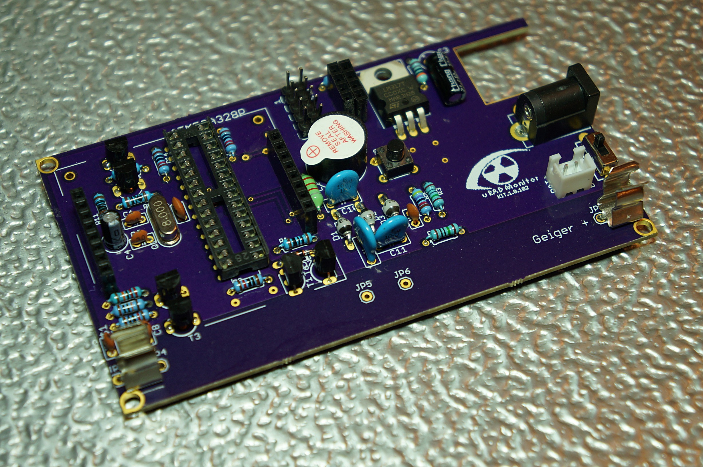
KIT1.0:
![]() KIT1.1:
KIT1.1:![]() The best thing about this update is the high voltage inverter update, that now uses a choke instead of the custom ferrite core transformer. So all this can be built in just a couple of minutes with readily available components, for a low cost.
The best thing about this update is the high voltage inverter update, that now uses a choke instead of the custom ferrite core transformer. So all this can be built in just a couple of minutes with readily available components, for a low cost.The software has been updated as well, having nice improvements in place like timeout for the LCD backlight or UI split into pages, to show all the relevant details and measurements grouped together. Just press the main button to navigate through them.
Open Source IOT Platform
Open-Source, easy to build IOT Dosimeter with sensors and Internet connectivity to centralise data.
 Radu Motisan
 Mission accomplished.


 Here's Horia and Fabio, good friends from the


 And the masterpiece created by Akos, that you saw in one of the
 You'll find the complete code there as well, or you can use this


 To keep a safe distance between the aluminum foil of the battery and the bottom of the pcb (high voltage!), I used 4 self adhesive rubber shoes, like those intended for furniture.
 The MCP1700 needs 2 filtering capacitors to work properly. I’ve just replaced the original c3 with 1uf ceramic, the other one (Cout) was soldered on the back side of the pcb


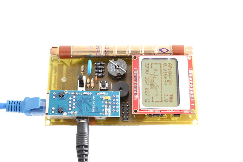 KIT1.1: