-
1Step 1
Fabricating Single & Double Sided SMT PCBS.
1) Stick the Toner transfer paper (TTF) onto a sheet of regular paper at the top edge for easy printer feed & crinkle free printing. I use painter's/masking tape for the job.
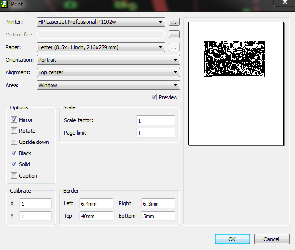
When printing from EAGLECAD add a 40mm top offset to accommodate the painter's tape offset and print 1:1 scale, black, solid with top layer mirrored, pads, vias and dimensions active.
![]()
-
2Step 2
2) Remove the print and inspect it, if you hold it up to a back light you will probably see porosity in the copper pours or thick traces. Do not touch the printed surface or you can flake the toner. Cut out the print leaving about a (5mm) border around the perimeter to permit securing onto the copper clad board. Border cut does not need to be precise or perfectly straight.
If you're doing a double sided board, Change the EagleCAD top layer setting to bottom layer (blue) and disable the mirror option in the print pop up. Print on fresh TTF for the bottom layer.
-
3Step 3
Go to step 4 for single sided boards.
For double sided boards with thru hole parts: Place a TTF print face up on the board and align to take strips of painter's tape along the 5mm border. Secure with bits of tape on the sides. Now use a large safety pin or the pin cap from a Krazy Glue tube, carefully press a pinpoint punch mark in the centre of any thru hole pads near the corners of the layout so the copper clad is marked. I usually add custom pad/vias just for this purpose, perimeter machine screw locations are good as well. Once you have 3 or 4 corners marked, carefully remove the TTF print and use a regular 'bobby' pin to pass thru each punched hole in the TTF. Now take the other TTF layer print and carefully punch thru the SAME pads with the bobby pin. I use a bit of backing cardboard to do this easily. It is important to punch the centres of all the pads you choose. Using a 0.8mm drill, carefully drill the registration punch marks you made on the copper clad. Offset mistakes here will be problematic later on when drilling the PCB for thru hole parts.=> Alignment/registration of thru hole components on both layers will be compromised. If you have NO thru hole components, the problem is minor. Unless an RF PC require aligned microstrips.
-
4Step 4
Prepare your Copperclad board by sanding the copper sides with 220 grit paper, removing any finger prints or corrosion. Clean with 90% + Isopropyl alcohol and Bounty paper towels, wipe repeatedly until clean. Do not handle the part of the board where you will apply the TTF. Do not blow on the board. Set down the clean board on a sheet of clean printer paper. Clean your hands with alcohol wipes as well.
Switch on your laminator to preheat properly.
-
5Step 5
Apply the TTF layer prints:
For a double sided board:
Place the copper clad on a piece of cardboard or paste board, place a TTF layer face down on the copperclad and align the registration pinholes using bobby pins. Once that is done, use painter's tape to secure the TTF to the copper clad board along the 5mm border you left when trimming the print. Remove the pins and flip the copper clad over. Now apply the other TTF layer with the same technique.
For a Single sided board, just apply the TTF print face down and secure with bits of painter's tape along the 5mm border.
-
6Step 6
Once your laminator has reached temperature (I use 325°F on the Apache AL13P for HP toner). Laminate the TTF onto the copperclad. Note my Apache Project does multi passes for you automatically. If you have another laminator or no Apache AL13P mod, you will have to pass the board thru at a higher temperature at least 8 times quickly, not burning your fingers in the process.
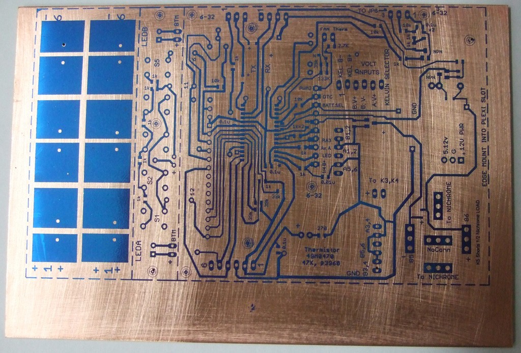
Once complete, place the board under water for a couple minutes and slowly peel off the TTF. inspect for any problems or bridges. Touch up with an Xacto blade if you see any bridges.
![]()
-
7Step 7
Now cut a piece of the craft foil to suit the board, double length if it is a double sided board. Dry the board properly (warming it on the laminator top cover can help. Carefully wrap the board with the colored foil face up, matte side to the board. Feed this into the laminator for a few passes as well or just once with the Apache mod project feature. When feeding the foiled board in at first, keep a finger pressure on the foil to keep it under tension so as not to crinkle when going in.
-
8Step 8
Allow the board to cool a bit and then peel off the foil.
The foil fills the pores in the thick toner areas, preventing pitting when etching. use your Xacto blade to check if the odd drill hole is also still covered by the foil, remove with the blade tip if so. At this stage if any trace or pad is damaged or incomplete, Use a SILVER sharpie pen to fill it in. If you over fill, scrape off the excess with an Xacto blade.
![]()
-
9Step 9
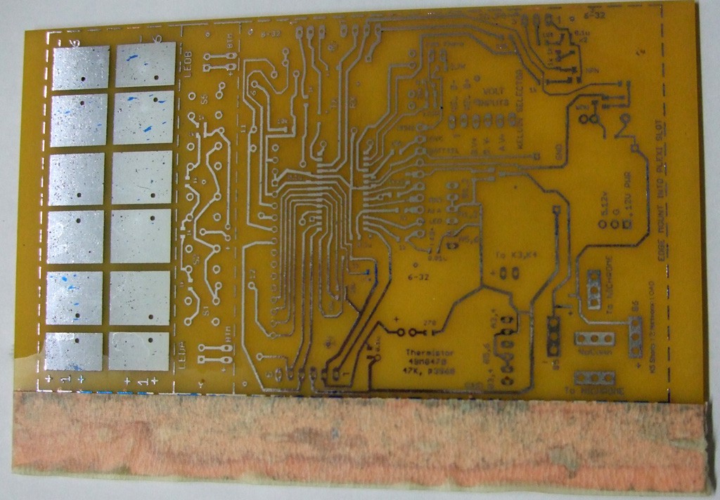
The hard work is done, now etch your board for the proper time monitoring it so as not to over etch.
The colored film may float off but the silvered backing does its job.
On this board I taped off the excess copper that was to be trimmed off to save etchant.
![]()
-
10Step 10
Making the solder mask stencil is simple with the laser cutter.
Export the cream layer ( top or bottom as required) from Eagle CAD direct to the Full Spectrum 40W driver, set at 50% speed & 50% power raster. With the raster cutting in the laser you don't need offsets mentioned below. They might be useful in tightly spaced boards so they are mentioned.
Place a single sheet of 3 mil laminator plastic in the middle of the laser cutter and place the laser head over the sheet (top left corner) . Use the perimeter trace function of the laser driver to ensure that the laser will not overlap the sheet edge or hit the bump stop.
Activate the laser print...and in a few minutes the stencil will be ready.
Note:You can also directly export a cream layer with pre-offset pads from Eagle. Go to DRC and in the Masks tab there is a Cream section. Set both the Min and Max to the offset distance you want. Your cream areas become 6 mil (or whatever) smaller than your pads. Just remember to change it back before sending to a real PCB manufacturer.
PCB /SMT MAKER LAB @ Home
This project outlines how to do advanced PCB making at home with proper tooling. Tooling includes a laminator and hobby laser.
 mosaicmerc


Discussions
Become a Hackaday.io Member
Create an account to leave a comment. Already have an account? Log In.