danjovic
-
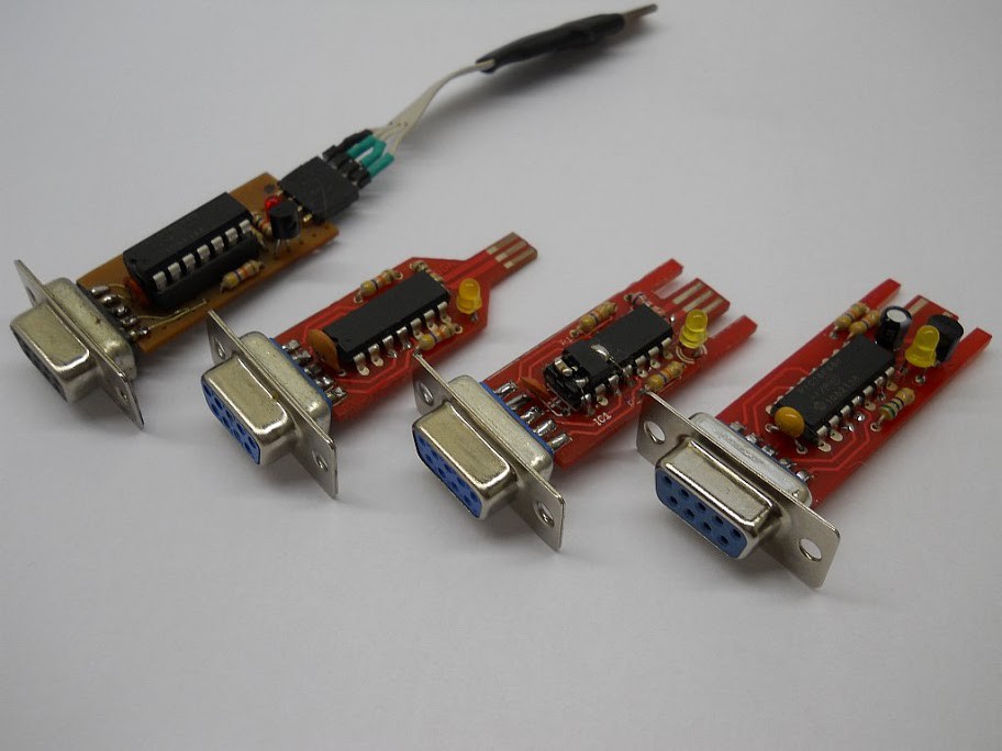
A bunch of prototypes
10/11/2015 at 16:21 • 0 commentsThe pictures on the manual are still from the last built version of the board (rightmost side in photo), which went through 3 prototypes (4 if you consider the protoboard ).
![]()
The prototype 2 (in veroboard) can be seen in action in the video below. Notice the programmer/tester fixture (as well as the DIY Pickit2 clone)
The square inch version is yet to be produced, but in the meanwhile the dropbox folder was added with an operation manual.
I think it is worth to remember that the square inch version of such project represents the opening of software and hardware of a previous commercial product (albeit being homemade).
-
Spinoff board: Joystick tester and programmer
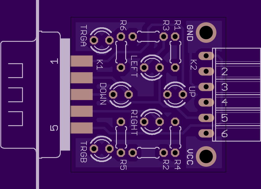
10/07/2015 at 00:13 • 0 commentsThe design of the AT26 Chuck took into account the eventual need for programming/reflashing the microcontroller. It means that the PGC PGD and MCLR pins are available on the Joystick connector. Hence an auxiliary board was designed to connect the signals of the ISP to the respective pins in the DB-9. As a bonus such board provides LEDS to test the activation of the Joystick lines (Up, Down, Left, Right, Trigger A and Trigger B).
The board also have two attaching points for attaching a a power supply by using alligator whenever the PICKIT is not being used to power the 'chuck and test boards.
![]()
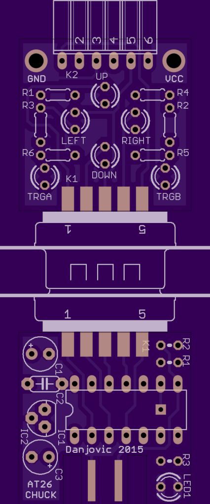
When programming/testing Both boards shall be connected as below:
![]()
AT26-Chuck
Adapter for playing Atari 2600 with Wii Nunchuck, with or without the accelerometers