Tim Savage
-
Making progress
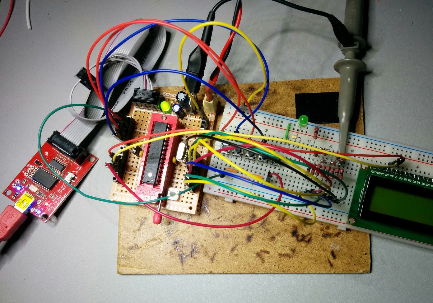
10/12/2015 at 14:55 • 0 commentsAfter a couple more hiccups with gcc-avr and optimisations I have a waveform being generated on a breadboard emulation of the FG-100 R2R DAC.
![]()
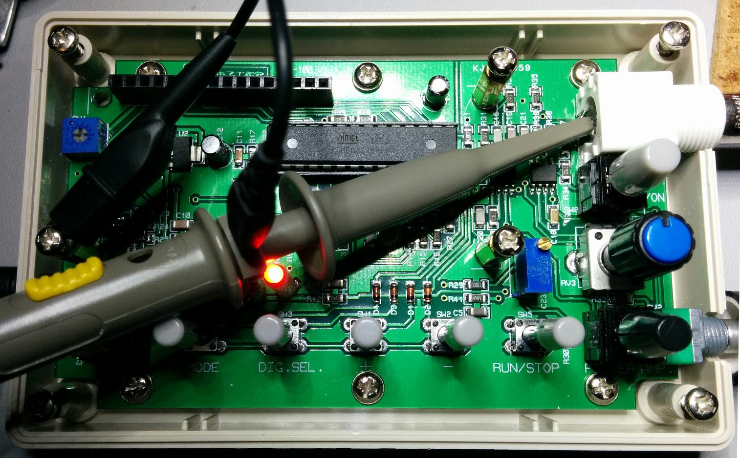
Dropping the micro controller back into the socket on the PCB:
![]()
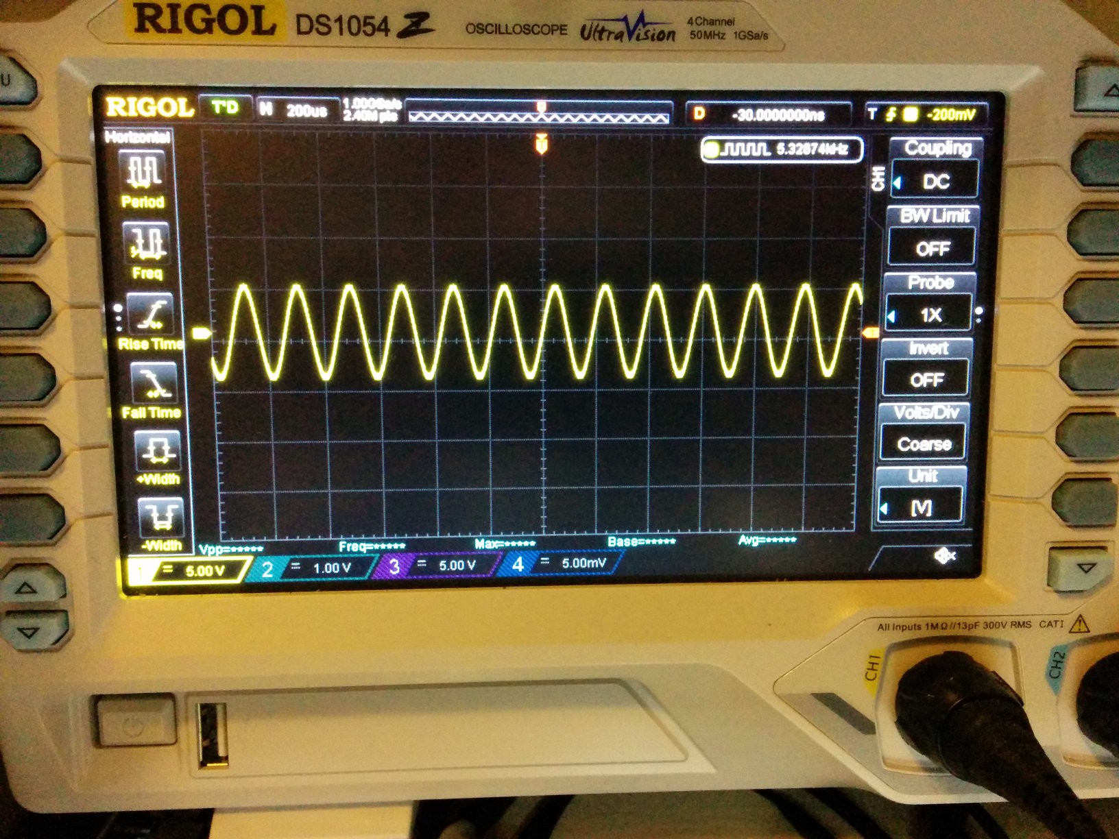
Results in a nice waveform on the scope
![]()
With the basic proof of concept looking good, time to move onto frequency control, and getting the LCD/UI working.
-
Bitten by the watchdog
10/12/2015 at 03:42 • 1 commentPart of my motivation for this project was to get some experience programming an AVR without the Arduino training wheels. This was partially because I like to really know how a system works and peaking under the covers is how you really learn and can better appreciate a good framework/library, secondly I need to minimise other processes (interrupts) to ensure the DDS works correctly.
I'm fully expecting to run into problems, some will probably be obvious to those who have more experience with embedded development, while I've been writing C for 15+ years the closest I've come to a micro in the past was a Palm Pilot! To this end I'm going to document all my issues/mistakes so others can learn from them as well.
My first issue is the output wave form goes back to 0V on the scope periodically before continuing again, time to start debugging... power rails look good, GND looks good, Reset pin isn't being pulled low, looking back at the scope the run period and blank periods are very uniform at ~65ms. From the datasheet 65ms also happens to be the default startup time delay, looks like my micro might be resetting periodically, to confirm I change the startup time delay to the alternative 4.1ms and the delay in my trace follows suite. Next what is causing the micro to reset? The code is really simple, some configuration for PORTD (set all to output), an 8bit counter and a while loop assigning the counter to PORTD. This generates a simple sawtooth wave and gives me an estimate of what kind of maximum frequency I'll be able to achieve (this will also give a comparison between the 16Mhz crystal in my development board with the 30Mhz crystal in the FG100.) There is no recursion or anything nasty in there that could blow the stack, if there was an overflow issue I'd expect it to crash the first time not after a few cycles. Going back to the waveform on the scope the run time is a very consistent ~17ms, back to the Datasheet which reveals:
Note: If the Watchdog is accidentally enabled, for example by a runaway pointer or brown-out condition, the device will be reset and the Watchdog Timer will stay enabled. If the code is not set up to handle the Watchdog, this might lead to an eternal loop of time-out resets. To avoid this situation, the application software should always clear the Watchdog System Reset Flag (WDRF) and the WDE control bit in the initialization routine, even if the Watchdog is not in use.
That is looking like my problem, the watchdog is being enabled and is resetting the micro every 16ms, even though the disable fuse set. So there you have it feeling a bit noobish with this one but at least my software debugging skills do translate!
-
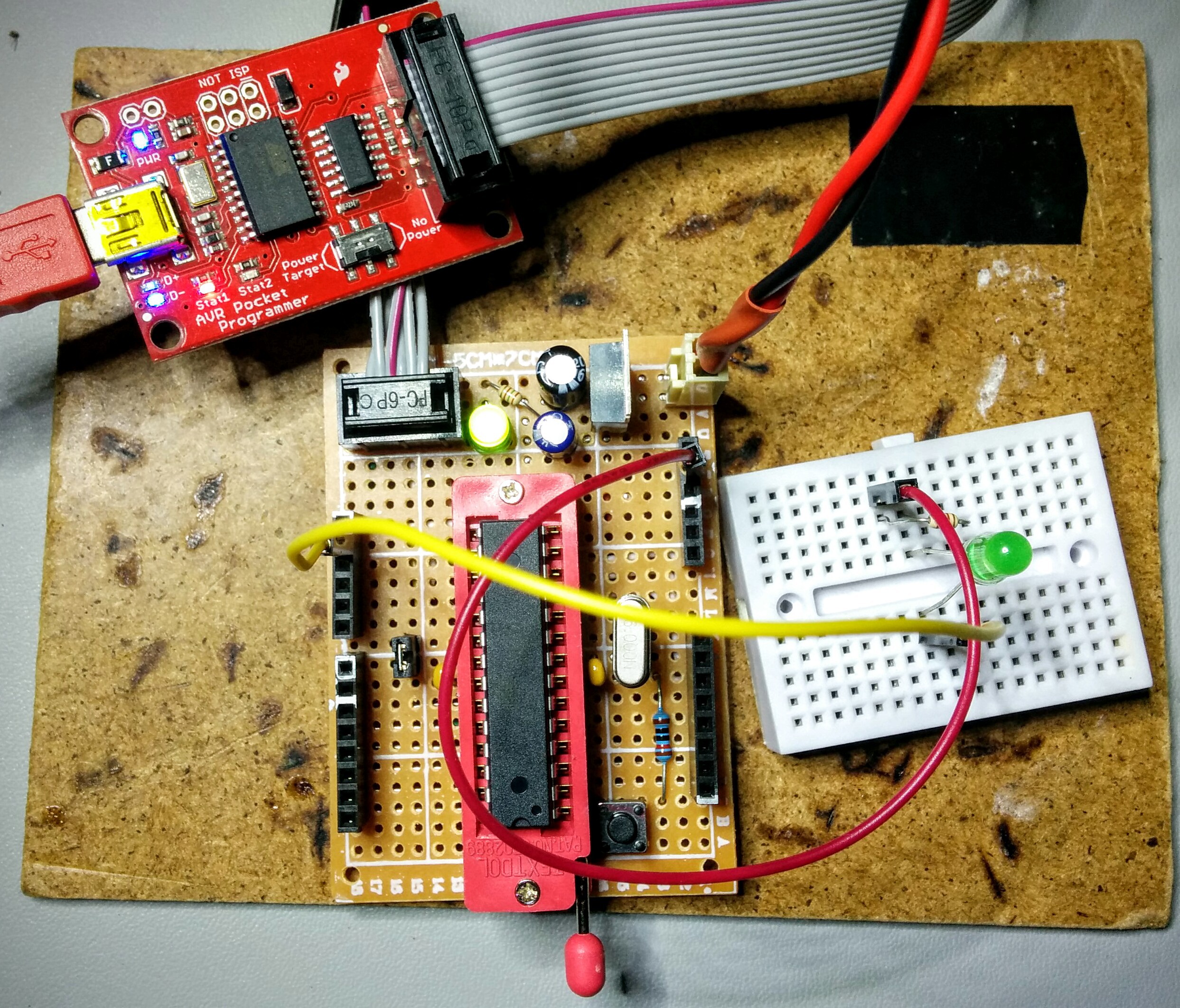
Made a start on firmware
10/09/2015 at 15:10 • 0 commentsBuilt up an AVR dev board to host the micro for programming and initial development. Initial code uploaded to github.
![]()
-
Pinout
10/08/2015 at 14:24 • 1 commentBetween the datasheet and probing with a continuity indicator pinout is quickly found.
![]()
There are a few pins free that could be used for other things. Maybe 27/28 could have a rotary encoder added.
Alternate Firmware for FG-100 DDS Function Gen
Reverse engineer the FG-100 pinout and develop alternate firmware that improves some of the shortcomings of the default firmware.