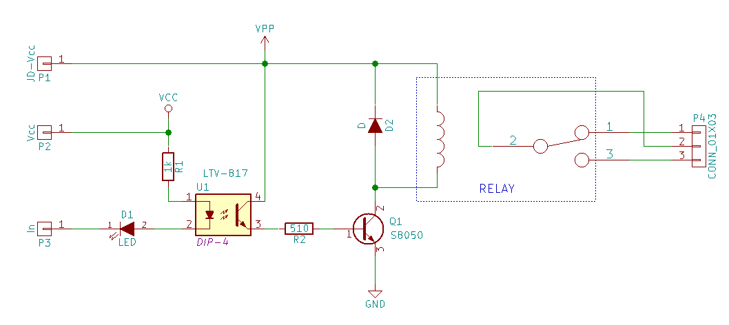
I did a lot investigations about this problem last days. It looks like device goes to a correct shutdown after I' switching on/off relays. Not every time, but with a high probability.
The first idea was - initial value in the GPIO register. Need to say, that almost all the logic of the GPIO operation in this device is inverted. Relays are off, when appropriate pin is in the high state. the door and power buttons are waiting for falling edge in the input signal. but on boot-up time, all the values in the RPi value registers are initialized with 0. This makes switch ON-OFF pulse on the time when I'm changing the GPIO pins mode from initial Z-mode to OUT. Looks it like this: after boot-up all the pins in Z-mode, the signal LEDs on the relay shield slightly on, but not enough to switch relay on. after I'm changing mode of the GPIO pin to OUT, relay shied switches ON and then immediately OFF. There is a pulse. My idea was that this pulse leads to the false event detection of the power button.
the problem was solved by setting boot sequence: switch all the pins to OUT, set low values to the pins used as inputs and high values for other. switch necessary pins to IN mode and start waiting the event. This makes things better, realy shield LEDs became looking proper, no switching pulses anymore, but switching relays on-off still causes a shutdown and false events on the power button. As alternative I've start using some python RPi.GPIO class options:
to init pin input pull-up resistance (didn't knew about these - this could made my schematics bit simpler):
GPIO.setup(channel, GPIO.IN, pull_up_down=GPIO.PUD_UP)
to init a value before changing PIN mode to a OUT
GPIO.setup(channel, GPIO.OUT, initial=GPIO.HIGH)
both tricks were taken from RPi.GPIO module documentation page
but I've continued my investigations. I had a way in mind to disable sensing a signals at time of the relays switching, but don't really want to implement this, while it will require synchronization between different processes in the system, or composing all the code in one huge binary responsible for everything. I even tried to skip the distortion using
GPIO.add_event_detect(channel, GPIO.RISING, callback=my_callback, bouncetime=200)
'bouncetime' option. Had no success.
But yesterday I've found that the one and only one relay on the shied do this distortion. And on this weekend I will check again this channel.

the D2 is under suspicion. At least the channel will function even if this diode is broken, but will make a power line distortions exactly like I have now. I'm crossing fingers )
Discussions
Become a Hackaday.io Member
Create an account to leave a comment. Already have an account? Log In.