 andreas.betz
-
1Step 1
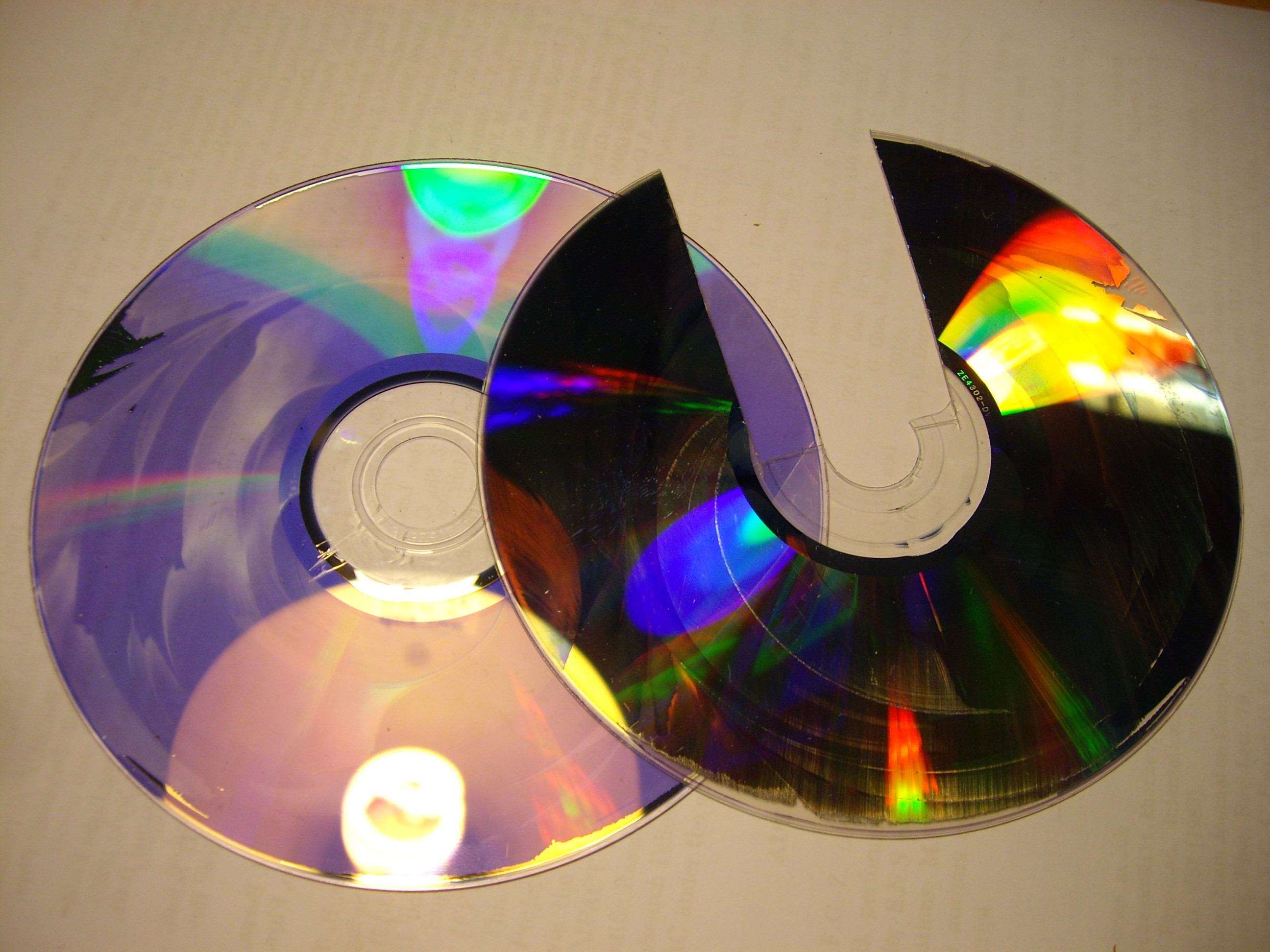
The diffraction grating
Take your DVD and split it into its 2 layers using flat tweezers or a scalpel. One layer should be (mostly) shiny, the other transparent with a purple hue. Cut a nice rectangle out of the shiny part.
![]()
-
2Step 2
Print / fab grating mount, sensor holders
-
3Step 3
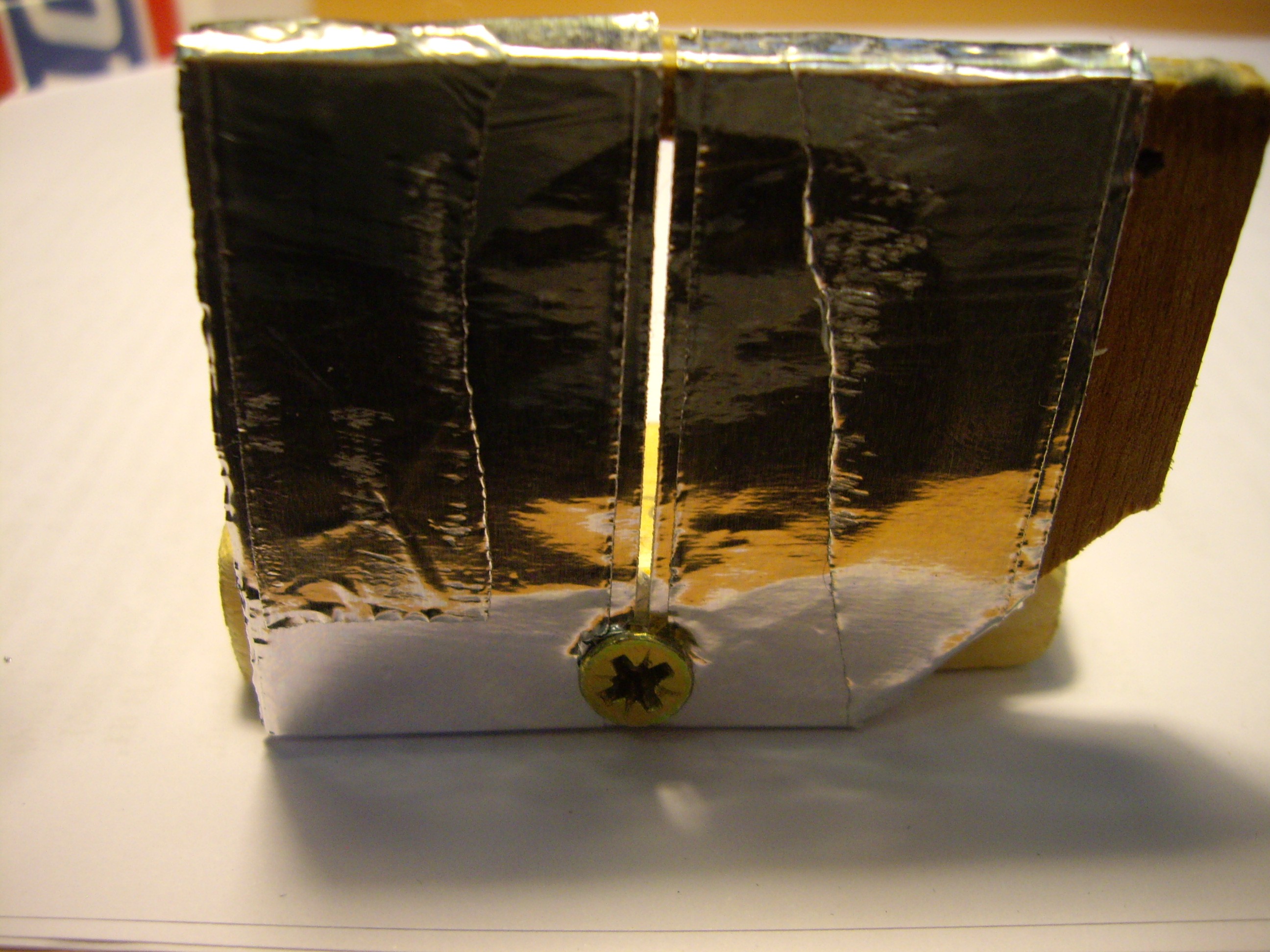
Entrance slit
The entrance slit for the light you want to examine can be made from 2 pieces of tin foil. Cut a large hole into a piece of wood/cardboard and tape the 2 pieces to it, leaving a small vertical gap.
![]()
-
4Step 4
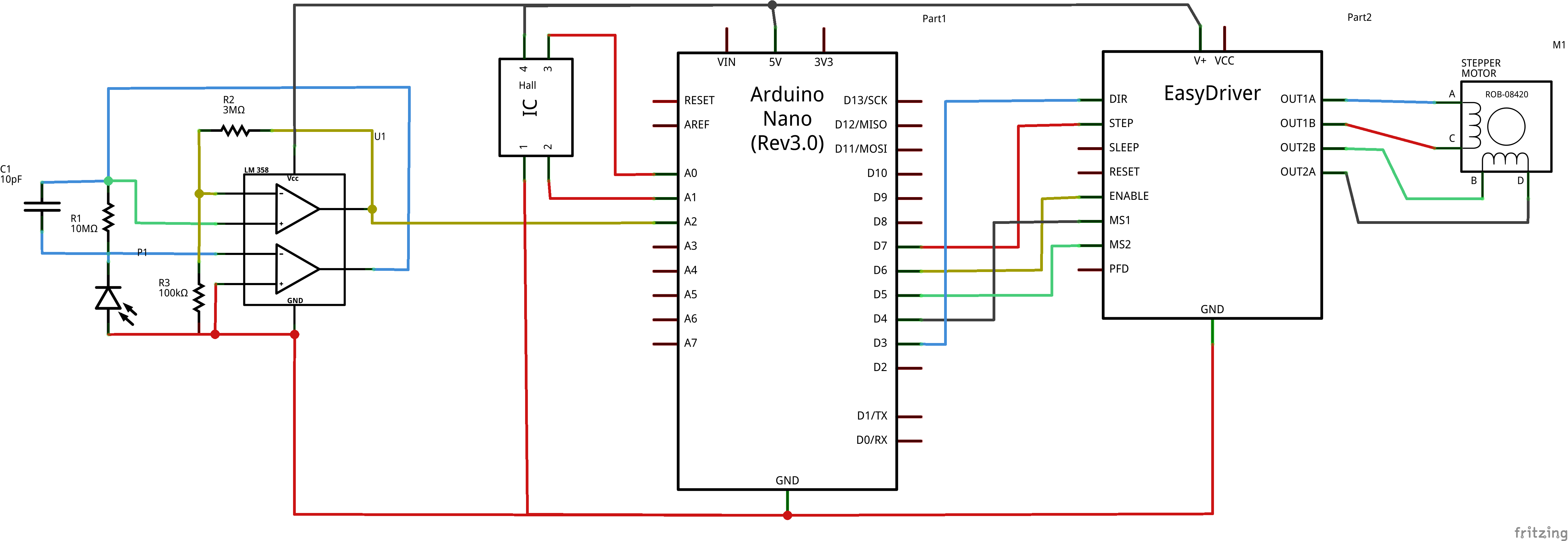
Electronics
Wire Nano, Easy driver, stepper motor, Opamp, photodiode and optionally Hall sensor.
![]()
-
5Step 5
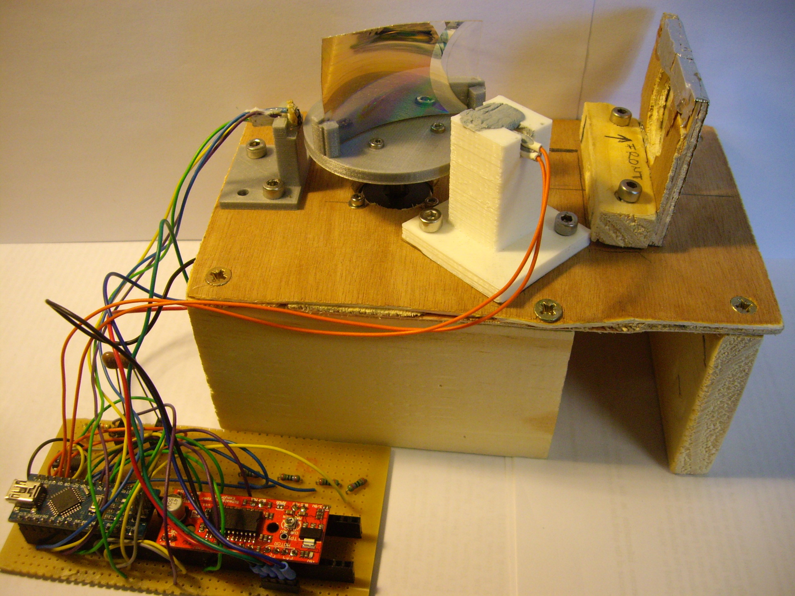
Assemble parts
![]()
-
6Step 6
Arduino Code
// Arduino code for THE SPINNING SPECTROMETER
//
// This code is released under the beerware license: As long as you
// retain this notice you can do whatever you want with this stuff. If we
// meet some day, and you think this stuff is worth it, you can buy me
// a beer in return.
// Andi


//Definitions
//
// HALL SENSOR
#define HallPin1 A0
#define HallPin2 A1
double a0;
double a1;
int HallMaxVal;
int Threshold;
int deltaHall;
//
// STEPPER via easydriver
#define stp 7
#define dir 3
#define MS1 4
#define MS2 5
#define EN  6
//
//PHOTODIODE
#define photoPin A2
int photoRead;
double photoVolt;
int ArraySize;
float integral = 0;
unsigned long lastTimeSampled = 0;
const float conversion = 5.0 / 1024 * 1e-6;


void setup() {
  Serial.begin(19200);
  //
  //PHOTODIODE
  pinMode(photoPin, INPUT);
  //
  // HALL SENSOR
  pinMode(HallPin1, INPUT);
  pinMode(HallPin2, INPUT);
  //
  // MOTOR CONTROL
  // set digital i/o pins as outputs:
  pinMode(stp, OUTPUT);
  pinMode(dir, OUTPUT);
  pinMode(MS1, OUTPUT);
  pinMode(MS2, OUTPUT);
  pinMode(EN, OUTPUT);

  digitalWrite(dir, LOW); //Pull direction pin low to move "forward"
  digitalWrite(MS1, HIGH); //Pull MS1, and MS2 high to set logic to 1/8th microstep resolution
  digitalWrite(MS2, HIGH);

  //
  //ADC SETUP
  // Define different ADC prescaler
  const unsigned char PS_16 = (1 << ADPS2);
  const unsigned char PS_32 = (1 << ADPS2) | (1 << ADPS0);
  const unsigned char PS_64 = (1 << ADPS2) | (1 << ADPS1);
  const unsigned char PS_128 = (1 << ADPS2) | (1 << ADPS1) | (1 << ADPS0); // standard UNO prescaler, equals 125kHz
  // set up the ADC
  ADCSRA &= ~PS_128;  // remove bits set by Arduino library
  // you can choose a prescaler from above. PS_16, PS_32, PS_64 or PS_128
  ADCSRA |= PS_32;    // PS_64~16.6 Sa/ms, PS_32~31.2 Sa/ms, PS_16~50 Sa/ms (=1MHz Sa.speed)

  //  Serial.println("go");

}
//
//
//
void loop() {

  //loop gets user input then either a) finds & goes to home pos. b) goes to home
  // or c) measures, sends data, then goes back to home

  // measurement is over first 135degrees, i.e. 600 points
  ArraySize = 600;
  photoRead = 0;
  int photoArray[ArraySize];
  int i;
  int k;
  int photoCount = 0;

  if (Serial.available() > 0) {
    int inByte = Serial.read();
    // do something different depending on the character received.
    // The switch statement expects single number values for each case;
    // in this exmaple, though, you're using single quotes to tell
    // the controller to get the ASCII value for the character.  For
    // example 'a' = 97, 'b' = 98, and so forth:

    switch (inByte) {
      //
      // HALL SENSOR + HOME POSITION
      case '1':
        HallMaxVal = HallMax();
        //      Serial.print("max value Hall sensor = ");
        //      Serial.println(HallMaxVal);
        Threshold = int(0.95 * HallMaxVal);
        //      Serial.print("Threshold set to ");
        //      Serial.println(Threshold);

        delay(100);
        // got to home position
        GoToZeroPos(Threshold);
        break;
      //
      // HOME POSITION
      case '2':
        // got to home position
        GoToZeroPos(Threshold);
        break;
      //
      // MEASUREMENT + BACK TO HOME
      case '3':
        //    Serial.println("case 3");
        for (i = 0; i < 733; i++) {
          SmallStepMode(500); // turn 165deg
        }
        delay(500);
        //motor turns 60deg from home, i.e. 267 points recorded
        for (i = 0; i < ArraySize; i++) {
          digitalWrite(stp, HIGH); //Trigger one step forward
          //    photoArray[photoCount] = analogRead(photoPin);
//          delay(2);

          //        integral = 0;  // integrate signal 300 times, i.e. 10ms
          //        for(int i=0;i<150;i++){
          //          photoRead = analogRead(photoPin);
          //          unsigned long now = micros();
          //
          //          integral += photoRead*(now - lastTimeSampled);
          //          lastTimeSampled = now;
          //        }
          //        photoArray[photoCount] = integral*5/1024;
          photoRead = 0;
          for (int i = 0; i < 50; i++) {
            photoRead += analogRead(photoPin);
            delay(1);
          }
          photoArray[photoCount] = photoRead / 50;
          photoCount++;


          digitalWrite(stp, LOW); //Pull step pin low so it can be triggered again
        }
        //      Serial.println("midway");
        delay(500);
        photoArray[0] = 0;  // always huge value??
        //print results for the whole 90deg
        //      Serial.println("results:");
        for (k = 0; k < ArraySize; k++) {
          Serial.println(photoArray[k]);
          //Serial.print(",");
          //delay(2);
        }
        //      Serial.println("");
        //      Serial.println("going back to start");
        for (i = 0; i < 1600 - 733 - ArraySize; i++) {
          SmallStepMode(500); // go back to starting position
        }
        break;
      default:
        delay(100); // don't do anything

    }
  }

} // loop end
//
//
//
//
// //////////////////////////////////////
// FUNCTIONS
//
// ////////////////////////////////////////////////////////////////////////////
// one 1/8th microstep foward mode function
void SmallStepMode(int stepDelay)
// inspired by the sparkfun easydriver code
{
  digitalWrite(dir, LOW); //Pull direction pin low to move "forward"
  digitalWrite(MS1, HIGH); //Pull MS1, and MS2 high to set logic to 1/8th microstep resolution
  digitalWrite(MS2, HIGH);

  digitalWrite(stp, HIGH); //Trigger one step forward
  delayMicroseconds(stepDelay);
  digitalWrite(stp, LOW); //Pull step pin low so it can be triggered again
  delayMicroseconds(stepDelay);

}
//
// ////////////////////////////////////////////////////////////////////////////
// find Hall sensor max value -> threshold
int HallMax() {
  int MaxVal;
  int read_old = 0;
  int read_new;
  int cnt = 0;

  digitalWrite(dir, LOW); //Pull direction pin low to move "forward"
  digitalWrite(MS1, HIGH); //Pull MS1, and MS2 high to set logic to 1/8th microstep resolution
  digitalWrite(MS2, HIGH);

  while (cnt < 1600) { // motor is microstepping 1/8th, so rotate 1 turn
    digitalWrite(stp, HIGH); //Trigger one step forward

    a0 = analogRead(A0);
    a1 = analogRead(A1);
    read_new = abs(a0 - a1);
    if (read_new > read_old) {
      read_old = read_new;
    }
    delayMicroseconds(470); // turn the stepper at 1ms per 1/8th step
    digitalWrite(stp, LOW); //Pull step pin low so it can be triggered again
    cnt++;
  }
  MaxVal = read_old;
  return MaxVal;
}
//
// ////////////////////////////////////////////////////////////////////////////
// go to zero, i.e. magnet=Hall sensor
void GoToZeroPos(int val) {
  int HallDiff = abs(analogRead(A0) - analogRead(A1));

  digitalWrite(dir, LOW); //Pull direction pin low to move "forward"
  digitalWrite(MS1, HIGH); //Pull MS1, and MS2 high to set logic to 1/8th microstep resolution
  digitalWrite(MS2, HIGH);

  while (HallDiff != val) {
    digitalWrite(stp, HIGH); //Trigger one 1/8th step forward
    delayMicroseconds(470);
    HallDiff = abs(analogRead(A0) - analogRead(A1));
    digitalWrite(stp, LOW);
  }
  //  Serial.println("position zero reached");
}
//
// ////////////////////////////////////////////////////////////////////////////
//
then use your favourite method to capture the serial data and plot the spectrum. Python works well for example.
The Spinning Spectrometer
A different take on the good 'ol spectrometer: spinning the grating to get visible light spectra. DIY style.
Discussions
Become a Hackaday.io Member
Create an account to leave a comment. Already have an account? Log In.