Close
0%
0%

Theta Printer

A 3D printer with 4 extruders that can move independently and simultaneously

Similar projects worth following
The Theta Printer is a platform for printing with as many different materials as possible. Whether it be different colors of plastic, wood, carbon fiber, chocolate, or anything else you can make an extruder for. Each extruder moves simultaneously and independently, allowing the printer to lay down 4 different materials onto the same object at the same time.

With most 3D printers, adding more extruders makes the machine slower and reduces the build volume. The Theta Printer overcomes this by using polar coordinates. A polar printer works kind of like an old fashioned record player. Your objects are printed onto a platter which spins. The advantage is that you can have many print heads. Each extruder is on the end of an arm which swings in and out. The spinning platter is called the ϴ ("theta") axis and the swinging arm is called the R axis. Together these replace the normal X and Y coordinates you're used to. A polar printer has a couple of advantages over normal cartesian 3D printers.

  1. Less moving mass means better acceleration
  2. Finer resolution, especially near the center
  3. Multiple toolheads without reducing build area

The spinning platform makes this machine ideal for integrating a 3D scanner. In addition, you can easily swap out an extruder for a mill or any other tool, making the Theta Printer the perfect all-in-one fabrication machine.


Specs

This machine is completely open source, under whatever license the RepRap project uses.

The complete parts list is on GitHub.

  • 48 × 3D Printed Parts
  • 20 × Lasercut Plywood Parts
  • 5 × Lasercut Acrylic Gears
  • 6 × Meters of Threaded Rod M8x1.25
  • 3 × Meters of Smooth Rod M8 Chrome Plated

View all 19 components

  • Quad Extrusion

    Tyler Anderson09/29/2014 at 06:28 5 comments

    I have been working on adding support for 4 extruders to Marlin, using [dob71]'s dual extrusion code as an example. Its on GitHub under the bipolar-quad branch. I've double checked everything and it compiles, but havn't had a chance to test it yet since I've been working on the semifinals video, which is uploading as we speak. Really getting tired of my own voice.

    In other news, I was getting terrible adhesion to the print surface. The problem seemed to be the tape I was using. It was shinier and smoother than regular blue masking tape. I ran to home depot and got some Scotch "Classic" painter's tape and things are sticking much better now.

    The aluminium platter may have been a bad idea. We chose it because we wanted something light, rigid, and thermally conductive. But in reality it just acts like a giant heat sink, cooling the part rapidly unless you have the heater turned on. Also it doesn't help that the heater is being run at half power (12V from the ATX instead of 24V). It reaches steady state somewhere around 60C, which is good enough for PLA but not great for ABS.

    Here are the latest test prints. Its having a lot of trouble with more complicated objects because the arm motors keep skipping steps. Don't know whats up with that.

  • Calibration

    Tyler Anderson09/27/2014 at 09:37 1 comment

    Now that I know that the firmware works, its time to dial in the machine. As you can see in the test prints from the last log, the extruders are horribly out of alignment with each other.

    I wrote a G-Code script to generate a test pattern for calibration. It has each extruder draw a large circle and two arcs. The circle is for calibrating the position of the endstops and the arcs are for calibrating the position of each extruder along the arm. The distance from the pivot point to the nozzle needs to be exactly 160 mm. Ideally, the patterns from each extruder should be directly on top of each other and the arcs should intersect at exactly the center of the platter. Here is the code:

    G94			; Set to native coordinates
    G28 Z0			; Home Z axis
    G1 Z10 F60		; and move up 10 mm
    
    ; Home each extruder
    T0
    G28 Y0
    T1
    G28 Y0
    
    ; Print test pattern with first extruder
    T0
    G92 X0 E0
    G1 E10 F100		; Prime extruder
    G1 X5
    G1 Y35 F1000
    G1 Z0 F60		; Move down to surface
    G92 X0 E0
    ; r = 2 * 160 mm * sin( 35 deg / 2) = 96.226 mm
    ; C = 2 * pi * r = 604.605 mm
    ; A_nozzle = pi * (0.35/2)^2 = 0.0962 mm^2
    ; V = A * C = 58.170 mm^3
    ; A_filament = pi * (3.0/2)^2 = 7.069 mm^2
    ; l = V / A = 8.23 mm
    G1 X180 E4.11 F1000	; Draw semicircle
    G92 E0
    ; 1/8 * full circle = 1.03 mm
    G1 Y40
    G1 Y-5 E1.03		; Draw arc
    G1 Y35
    G92 E0
    G1 X360 E4.11		; Finish circle
    G92 E0
    G1 Y40
    G1 Y-5 E1.03		; Draw second arc
    G1 Z1.5 F60		; Lift
    G1 Y45 F1000		; Retract arm
    
    ; Second Extruder
    T1 F1000
    G92 E0
    G1 E10 F100
    G1 Y35 F1000
    G1 Z0.2 F60
    G92 X0 E0
    G1 X180 E4.11 F1000
    G92 E0
    G1 Y40
    G1 Y-5 E1.03		; Draw arc
    G1 Y35
    G92 E0
    G1 X360 E4.11
    G92 E0
    G1 Y40
    G1 Y-5 E1.03
    G1 Z10 F60
    G1 Y45 F1000
    
    G93			; Switch back to cartesian emulation
    M18			; Disable motors
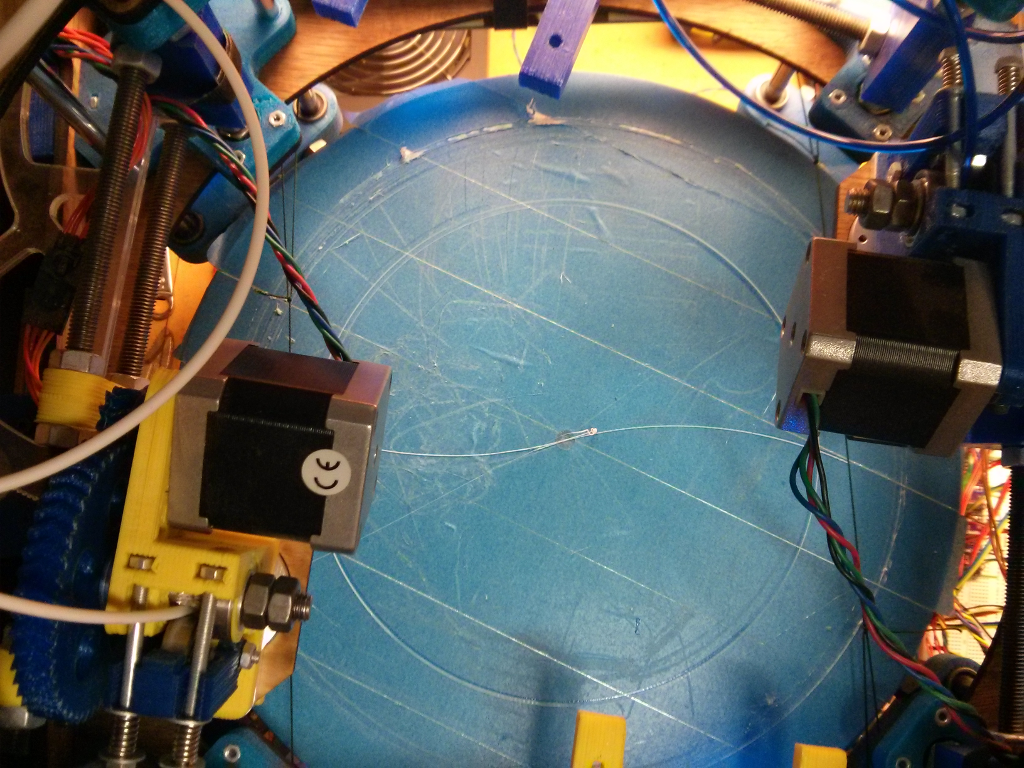
    And here is the resulting pattern:

    Its hard to tell from the picture, but the circles are way off and the arcs are lined up pretty well. I adjusted the position of the endstops in firmware by measuring the radius of each circle with calipers and comparing it with the expected value (96.226mm).

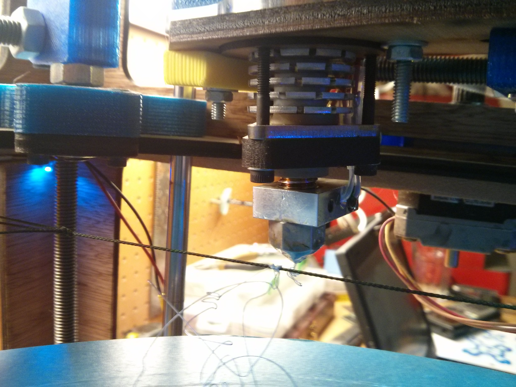
    Another problem is that the extruders ooze a lot when idle. The ooze gets carried over and stuck onto the print and it eventually builds up into big globs of plastic that the extruders crash into, causing them to skip steps. I tied some string so that the nozzles wipe across it when the arms retract, knocking off the excess plastic.

    I'm having a lot of trouble getting the nozzles level with each other and the build surface. Its like their vertical position keeps changing.

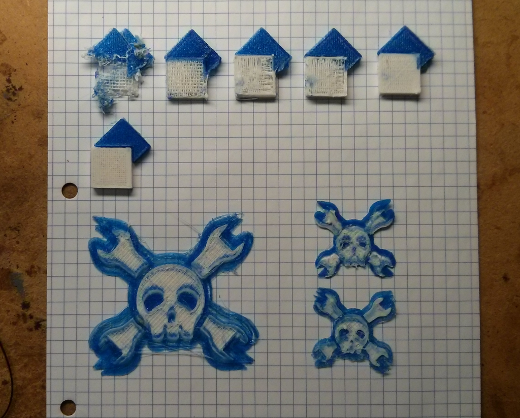
    Here's the latest test squares along with a couple failed tries at the Jolly Wrencher, which I put up on Thingiverse.

  • Captains Log, Stardate 56925.25

    Tyler Anderson09/25/2014 at 08:27 0 comments

    Dual extrusion is working! Through the magic of Git, I have managed to combine a firmware that handles multiple extruders on independent axes with my firmware that does the bipolar conversion. Amazingly, the thing compiles and runs. I reworked the way Marlin stores the current position in both coordinate systems internally. The way it was doing it before was confusing me and causing bugs while homeing. Also had to add support for multiple sets of endstops per axis. For more details check the github

    First dual extrusion test prints are promising, but clearly a lot of work still needs to be done. Definitely need some way to clean the extruders when switching between them. Having flashbacks about dealing with oozebane in skeinforge. No cleanup was done on these aside from removing whatever excess I could with my fingers.

  • Holy Crap

    Tyler Anderson09/18/2014 at 08:52 0 comments

    Uh oh. I'm in the competition. Guess I better get to work.

    There's no chance of having the Decapede ready any time soon, so I bought some stepper drivers off eBay (Geeetech DRV8825) and started wiring them up on a breadboard and connecting them to the AUX pins on the RAMPS. Unfortunately, they did not come with thermal adhesive for the heat sinks.

    The only thing the RAMPS needs in order to drive 2 extruders is an additional stepper driver. To run all 4, though, I will need to wire up some extra MOSFETs and voltage dividers for the extra heaters.

    On the software side, I'm going to try merging the multiple extruder support from Marlin X2 into Bipolar Marlin. The RepRap X2 is a Prusa variant with dual extruders on independently moving X carriages. It may not look similar to the Theta printer, but from a programming standpoint, this is exactly what I need.

  • Electronics

    Tyler Anderson08/21/2014 at 05:19 0 comments

    Electronics


    With all 4 extruders, the platter, and the Z axis, the machine requires 10 independently controlled motor axes. No current 3D printer controller is capable of driving more than 5 stepper motors at once. While researching options to overcome this limitation we discovered a project called Decapede , which aims to sell a 3D printer / CNC controller that can drive 10 motors (thus the name). The Decapede can also drive 8 heaters and read from 8 thermal sensors. The processor is an Arduino Mega 2560. More information can be found at http://printm3d.com/portfolio-item/decapede/ or http://reprap.org/wiki/Decapede.

    We got in contact with the developers early on, who incorporated our feedback into the design and offered to let us test a prototype. Unfortunately, as time went on it became evident that the Decapede would not be read in time to complete the senior design project. Currently, several prototypes have been produced and various bugs have been discovered in the design. Once the issues are resolved, the developers plan to launch a crowdfunding campaign to fund production.

    Our fallback plan was to use a standard 3D printer controller, the RepRap Arduino Mega Polulu Shield (RAMPS) version 1.4 (http://reprap.org/wiki/RAMPS). RAMPS can drive 5 motors and 3 heaters. This means that we would be unable to run all 4 extruders. By splicing the motor connections we were able to run two axes in parallel, thus allowing us to drive two extruders with the standard RAMPS controller.

    Power Supply

    A standard ATX computer power supply was chosen for several reasons. First, they can provide the high power necessary to run the machine. Secondly, they are cheap and readily available. They also meet the 12 Volt requirement of our electronics. Modern switching power supplies are also very efficient and provide clean output.

    In order to select the appropriate power supply we first had to determine the power requirements of the machine. The following chart shows a breakdown of each component and it’s peak wattage. We expect each component to draw less power under normal operation. Also, although we have a 240 Watt heated bed, it will only draw 120 Watts since it will only be operating at 12 Volts as opposed to 24.

    ItemQtyOhmsVoltsAmpsWatts
    Stepper Drivers10n/a124.00480.00
    Hot Ends46.8121.7684.71
    Heated Bed1n/a1210.00120.00
    CPU1n/a50.502.50
    Extruder Fans4n/a120.084.00
    Total:691.21

    Our selected power supply is a Thermaltake Toughpower 750W purchased from Newegg for $70. In order to convince the power supply to operate outside of a personal computer, we had to ground the PS_ON line. This was done by connecting a paperclip between the green wire and a black wire.Another important consideration is that not all power supplies are capable of delivering their maximum wattage on the 12 Volt line. We verified that our chosen power supply would deliver 720 Watts at 12 Volts.

  • Heated Bed

    Tyler Anderson08/21/2014 at 05:15 0 comments

    Aluminium Platter

    The cross sectional view below shows the original design for the platter. It consists of two layers of circular plywood. The lower piece has a hole in the middle where a nut is glued in place to connect it to the shaft. The upper piece is connected to the lower piece by countersunk bolts around the perimeter.

    In testing, the wooden platter proved to be inadequate. The top of the platter is required to be extremely level. Its height could not vary by more than 0.25mm across the entire surface (the height of a single plastic layer on a printed object). Unfortunately, the plywood was naturally warped far beyond the tolerance. This test video demonstrates the problem (http://youtu.be/nC2cthvXTew).

    An attempt was made to level the wooden platter by soaking it in water and clamping it in place until dry. This was unsuccessful. We decided to construct a new platter out of machined aluminium, which would have no trouble meeting our flatness tolerance. It would also be better for the heated bed since aluminium is much more thermally conductive than wood.

    A suitable plate of 7075 aluminium was acquired from the scrap pile in the machine shop. This picture shows the plate being machined on a CNC mill to a diameter of 304.8 mm and a thickness of 4.2 mm. A hole was drilled and tapped in the center for the M8x1.25 shaft.

    Heated Bed

    The original design did not consider the need for a heated build platform. This is standard equipment on all FDM 3D printers. As an object is being printed, thermal contraction causes the bottom of the object to shrink while the top of the object is still hot. This causes the entire object to warp. In the worst cases, the object will completely peel off of the build surface before printing is completed.

    The larger an object is, the more warping occurs. Also different plastics will warp more than others. Since the purpose of this printer is to build large object from multiple material, a heated build surface is essential.

    Most 3D printers use an electric heating element and a temperature sensor under the build surface. Unfortunately, the spinning platter on this machine means the wires running to the heater would get wrapped around the shaft. The solution is simple. The electrical connections are passed through a slip ring to prevent the wires from twisting around the shaft. After extensive research, we found a circular 200W heater with a 240 mm diameter and a 12 connection slip ring.

    The slip ring replaced the central bearing underneath the platter. A hollow coupler was used to connect the shaft to the slip ring. Holes were drilled in the side of the coupler for the wires to pass through. Since each connection on the slip ring is only rated for 2 Amps, multiple wires were used in parallel to carry the full current of the heater. The heater itself is designed to operate at 24 Volts. Unfortunately our power supply only provides 12 Volts. Although the heater is run at half power, it still gets sufficiently warm given enough time.

  • Concept

    Tyler Anderson08/21/2014 at 05:11 0 comments

    Platter and Middle Section (θ1 Axis)

    The round table where object will be printed on. It is driven by a stepper motor and a large round gear, so it can move both directions clockwise or counter clockwise. This round table is approximately 320 mm in diameter. Rollers around the perimeter support the weight of the platter and keep it level.

    The gear ratio for this axis is 385:18. In order to maximize the resolution of the printer, the gear was made as large as possible while still leaving room for the drive motor. For each increment that the stepper motor moves, the platter turns 0.084°.

    Extruder Arms (θ2 Axis)

    The radial movement component which functions to move the four extruders. Each sub-component is driven by a stepper motor and a protractor gear. It swings the extruder in and out while printing.

    The gear ratio for this axis is 450:18. This allows it to match the resolution of a RepRap (0.2 mm / step).

    Z Axis

    The z-axis component which will be used to move the entire middle section up and down. It has four-threaded rods at the corners. Those rods are synchronized by a timing belt which is driven by two stepper motors. The rods are also threaded into nuts in the middle section. As the rods rotate, the nuts are pushed up or down.

    The smooth rods are 8 mm in diameter. The middle section connects to these rods with LM8UU linear bearings. The threaded rods are M8x1.25. They are driven by the timing belt with 36 tooth gears.

  • Software

    Tyler Anderson04/19/2014 at 03:43 0 comments

    Some people have been asking about the software side of things. Right now what we have is a modified version of the Marlin firmware. Its based on the work done to make Marlin work with Delta printers, with the math changed to do the conversion to bipolar coordinates. The firmware works in two modes:

    Cartesian emulation mode

    In Cartesian emulation mode, the firmware does the conversion from Cartesian to bipolar coordinates on the fly. Basically it acts like a normal printer and you can use it with standard slicing software. The only difference is that you must specify the speed in °/s instead of mm/s. This has the side effect of throwing off the estimated completion time in the host software.

    Native bipolar mode

    In this mode, the G-Code is given to the printer directly in bipolar coordinates. It requires special slicing software (which doesn't exist yet) but it is the only way to take advantage of the full capabilities of the printer.

    You can switch between these modes using the G93 and G94 commands. G92 works as you would expect in each mode. Homing also works (G28) except it is disabled for the platter (θ₁ axis), since it is homeless.

    Currently there is no support in the software for using more than one extruder. The electronics package we intend to use for driving all 10 motors has not gone into production yet. Hopefully this will happen soon, since people have started throwing buckets of money at that company. If not, I may have to make a one-off order to OSH Park and get the ball rolling.

View all 8 project logs

Enjoy this project?

Share

Discussions

George I Fomitchev wrote 08/12/2016 at 12:17 point

Do you have assembled unit? we could try our 3.5W and 5.6W lasers to install on this device...

  Are you sure? yes | no

Films4You wrote 06/02/2015 at 21:18 point

  Are you sure? yes | no

changdy009 wrote 01/29/2015 at 09:11 point

Dear Tyler Anderson, Can you upload a video about your 3D printer, when it is working?

  Are you sure? yes | no

[deleted]

[this comment has been deleted]

Tyler Anderson wrote 11/27/2014 at 07:56 point
Still going. Just got a job at MatterHackers and they are excited about this machine, so thats good news for the future.

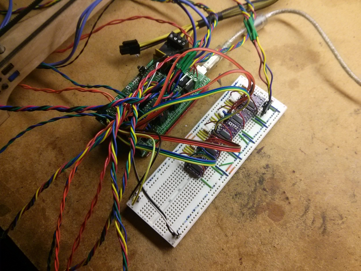
Since the Decapede never came to fruition, I am using a breadboard to expand a standard RAMPS to handle the extra stuff. The thing is a total rats nest. The breadboard has 5 stepper drivers, 2 voltage dividers for reading thermistors, and 2 MOSFETs for driving heaters. This is all connected to AUX-3 and 4 on the RAMPS. The circuitry is copied from the RAMPS 1.4 schematics ( http://reprap.org/mediawiki/images/f/f6/RAMPS1.4schematic.png ). Here are the pin assignments ( https://github.com/unlimitedbacon/Marlin/blob/bipolar-quad/Marlin/pins.h#L319 ) and their locations on the board ( http://reprap.org/mediawiki/images/c/ca/Arduinomega1-4connectors.png )

I wouldn't recommend this as your first printer unless you really know what you're doing. This machine works as a proof of concept, but there are A LOT of rough edges. 3D printers are troublesome machines to begin with, and with this one that is only compounded.

  Are you sure? yes | no

[deleted]

[this comment has been deleted]

Tyler Anderson wrote 11/29/2014 at 00:45 point
I would love to have other people building these and contributing. Just wanted to make sure you know what your getting into. I'll be glad to help in any way I can.

The main issue right now is that the bed refuses to stay level. It wobbles around as it spins. I'm planning to completely redesign the middle section to eliminate this. Calibrating the machine is also frustrating, but it will be greatly simplified for you since you only plan on doing 1 extruder at first. There are a ton of other issues that I have documented in TODO.md ( https://github.com/unlimitedbacon/Theta-Printer/blob/lasercut/TODO.md )

I highly recommend that you use 1.75 mm bowden extruders ( http://e3d-online.com/E3D-v6/Full-Kit/v6-1.75mm-Universal-Bowden ) instead of the 3.00 mm direct drive extruders I have. This will greatly reduce the moving mass and make things much less crowded.

Changing the movement to be truly radial is something that I was planning to do for version 2, mainly because I saw the R-360 ( http://replicatorwarehouse.com/r-360-modular-printer-with-rotating-bed/ ) and slapped myself in the forehead.

As for reading material, have a look at the RepRap Magazine ( http://reprapmagazine.com/issues.html )

  Are you sure? yes | no

zhangguodong wrote 10/31/2014 at 06:07 point
How to print 200 * 200mm objects (using a single extrusion)?

  Are you sure? yes | no

zhangguodong wrote 10/31/2014 at 06:00 point
I have a question:
Whether the object can be placed in the center of the bed single extrusion printing?

  Are you sure? yes | no

zhangguodong wrote 10/31/2014 at 06:02 point
Can single extrusion print objects placed in the center of the bed?

  Are you sure? yes | no

Tyler Anderson wrote 10/31/2014 at 06:39 point
Yes, but the speed decreases the closer you get to the center. Its faster to print objects away from the center if possible.

  Are you sure? yes | no

zhangguodong wrote 10/31/2014 at 10:58 point
I have 5 questions:
1、Y homing centers in the bed?
2、Single extrusion using G93?
3、Its faster to print objects away from the center if possible?(Automatically adjusting the speed of the extruder?)
4、Set slic3r Print Center (0,0,0)?
5、How to adjust the number of steps X Y axis?

  Are you sure? yes | no

Tyler Anderson wrote 11/01/2014 at 05:22 point
It looks like you have some interesting questions, but they are kind of getting lost in translation. I'll try my best to answer them.

1. Calibrating the Y axis ( you could also call it the r axis or θ₂ axis) is done by setting Y_MAX_POS in Configuration.h. It needs to be done separately for each extruder. The value is determined by running the calibration script I posted in the project logs. 50° is a good starting point. Using calipers, measure the diameter of the circle drawn by each extruder. Divide that by 2 to get the radius and then convert it to degrees using trigonometry. Find the difference between what you got and what it is supposed to be (35°) then adjust Y_MAX_POS by that amount.

2. Single extrusion works in both native mode (G94) and cartesian emulation mode (G93).

3. The speed is not adjusted automatically. It is just a natural effect of using the spinning platter.

4. Go to File > Preferences and make sure you are in expert mode. Under Printer Settings / General, set the bed size to 320x320 and the print center to 0x0.

5. Set DEFAULT_AXIS_STEPS_PER_UNIT in Configuration.h.

  Are you sure? yes | no

zhangguodong wrote 11/01/2014 at 12:46 point
Thank you to answer!
How accurate calibration steps XY axis?

  Are you sure? yes | no

Tyler Anderson wrote 11/01/2014 at 22:03 point
The calculations for determining the steps per unit are shown in Configuration.h ( https://github.com/unlimitedbacon/Marlin/blob/bipolar/Marlin/Configuration.h#L363 ).

The gear ratios were chosen so that the θ₁ would match the accuracy of a normal RepRap near the perimeter. As you move closer to the center, the accuracy increases to infinity. This is also a natural effect of using the spinning platter.

The θ₂ axis also matches the accuracy of a normal RepRap.

  Are you sure? yes | no

zhangguodong wrote 11/02/2014 at 05:32 point
Use gear for: GT2 18 teeth?

  Are you sure? yes | no

zhangguodong wrote 11/02/2014 at 15:20 point
Do you want “R、 C、 A、V、 A_filament、 L” setting in the firmware?

  Are you sure? yes | no

zhangguodong wrote 11/03/2014 at 12:50 point
I'm sorry!
I do not know where to set the "R, C, A, V, A_filament, L"
Firmware?

  Are you sure? yes | no

Josh Wright wrote 08/29/2014 at 00:41 point
Would love to start making my own!

  Are you sure? yes | no

Guille wrote 08/25/2014 at 22:38 point
@Tachyon, you mean CLV, constant linear velocity? A regular wheel is CAV.

  Are you sure? yes | no

Tachyon wrote 08/29/2014 at 15:14 point
Yeah, CLV is what I meant.
And I do still see this as a big issue with this design. Without CLV, print resolution will be inconsistent across the radius of the print platform. Getting progressively worse as you move out from the centre of the platform.

  Are you sure? yes | no

Samuel Wittman wrote 04/18/2014 at 17:03 point
Just to verify, you use this modified marlin firmware, and then use a standard slicing software?

I was digging around in Cura, and I couldn't find a decent way to specify tool changes. Slic3r has the custom toolchange.gcode thing, but so far it looks like Cura only lets you speficy the offset between each head.

I might eventually go back and build one of these (with all credit to you, of course), simply because I'd never have to change my filament ever again. I suppose I could do this on a standard cartesian system, but it would feel so unwieldy to me.

How do you keep all of your printheads level to each other?

  Are you sure? yes | no

Tyler Anderson wrote 04/19/2014 at 03:53 point
Correct. The goal is to make it compatible with as much of the regular toolchain as possible. I made a log entry about the current state of the software.

Its nice to know other people are interested in this, but you might want to hold off on building your own until version 2 or 3. There are A LOT of kinks to be worked out. Leveling is one of them. You do it by adjusting nuts on the threaded rods, but is all trial and error. Getting two extruders and the bed level with each other is hard. Doing it with all 4 is going to be a colossal pain in the ass. In the future I'm definitely going to look into some kind of auto-leveling system.

  Are you sure? yes | no

Samuel Wittman wrote 04/15/2014 at 17:23 point
This is really cool.

  Are you sure? yes | no

RodolpheH wrote 04/15/2014 at 16:22 point
I'm wondering what software you're using ? I look forward to get more informations about your 3D printer, it looks really gorgeous!

  Are you sure? yes | no

Tyler Anderson wrote 04/19/2014 at 03:55 point
Modified Marlin for the firmware and regular old Slic3r/Printrun for everything else. Check out the log entry.

  Are you sure? yes | no

Eric Evenchick wrote 04/15/2014 at 15:12 point
The dual extrusion video is an interesting one to watch. Using polar coordinates is definitely a novel solution. I'm trying to think of what the disadvantages of it would be, but the ability to use two extruders on the same part simultaneously is a pretty huge plus.

  Are you sure? yes | no

Tachyon wrote 05/01/2014 at 11:38 point
The main disadvantage that I see is that your printer's resolution would be inconsistent across the print area. The print resolution would range from something approaching infinity at the centre of the print circle, to some approaching really bad at the outer diameter of the print circle.
One way around this would be to use some sort of CAV (constant angular velocity) drive system for the print table such that the print head traverses the same distance per unit of time at all points in the print circle's diameter.

  Are you sure? yes | no

Tachyon wrote 08/29/2014 at 15:22 point
The other issue I see is that while this would be great for printing things like gears, wheels, vases, and other round shapes, it would likely have issues with more square or rectangular shapes.
Imagine printing a lego brick on this, or another angular shape with a filled centre. Imagine the printhead paths and how this printer would move over those paths, especially without CLV.
For one thing, I imagine you'd have to print non round objects offset from the centre of the print platform.

Personally, I think I'd want one printer like this and one that uses more standard cartesian printing. One would be awesome for round things like gears and wheels. The other would be awesome for angular things with straight edges.

  Are you sure? yes | no

Similar Projects

Does this project spark your interest?

Become a member to follow this project and never miss any updates