-
Putting It All Together
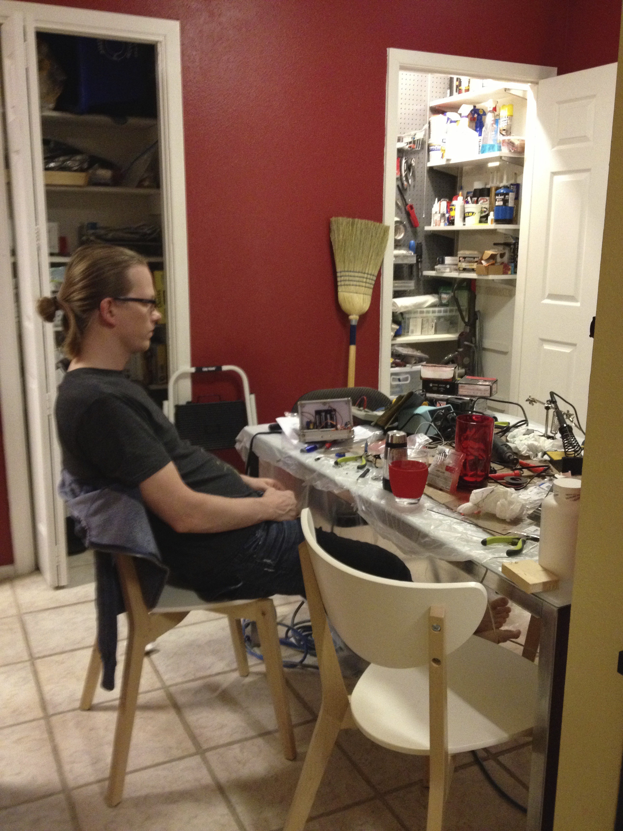
10/21/2015 at 07:29 • 0 commentsSoldering 12 boxes was a lot more work than I anticipated. 5 of my friends were helping, and it still took us quite a while. Here is the aftermath of one of our soldering sessions:
![]()
Here are the finished 12 boxes (my wife did a great job decorating them with her vinyl cutting machine):
A friend taking inventory and setting them up the night before the wedding:
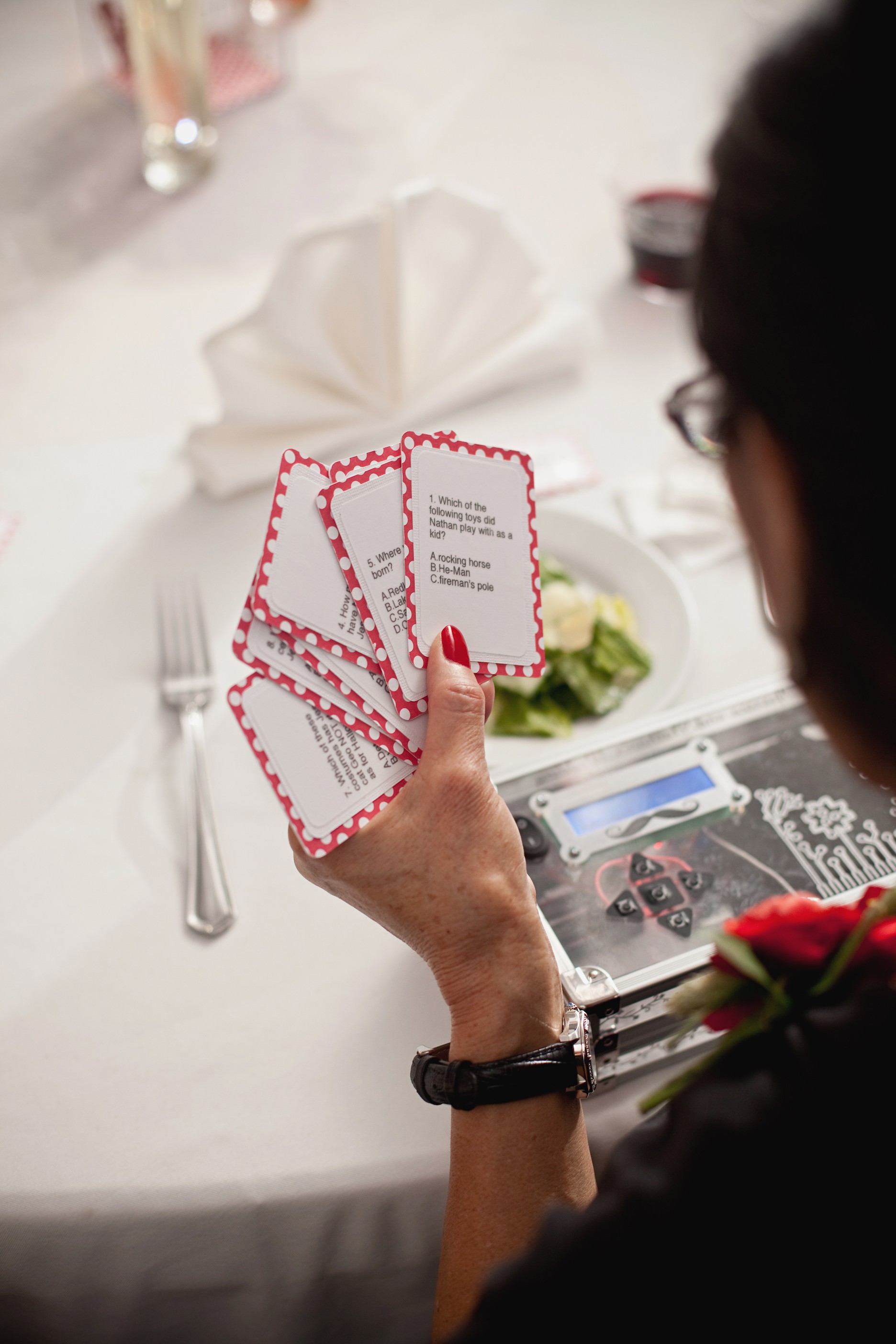
My wife made these cool question cards:
![]()
Here is the centerpiece for one of the tables at the wedding:
![]()
The two tall vases are filled with oil and colored water. They essentially turn into DIY lava lamps when you drop alka-seltzer tablets in them, so one of the prizes in the box was alka-seltzer tablets. The other prize was a token to redeem a Hawaiian Lei for one of the dances later, which resulted in us receiving all of the Leis:
![]()
Here is the Lock Box Wedding footage:
Here is a demo of the lockbox:
-
The Interface
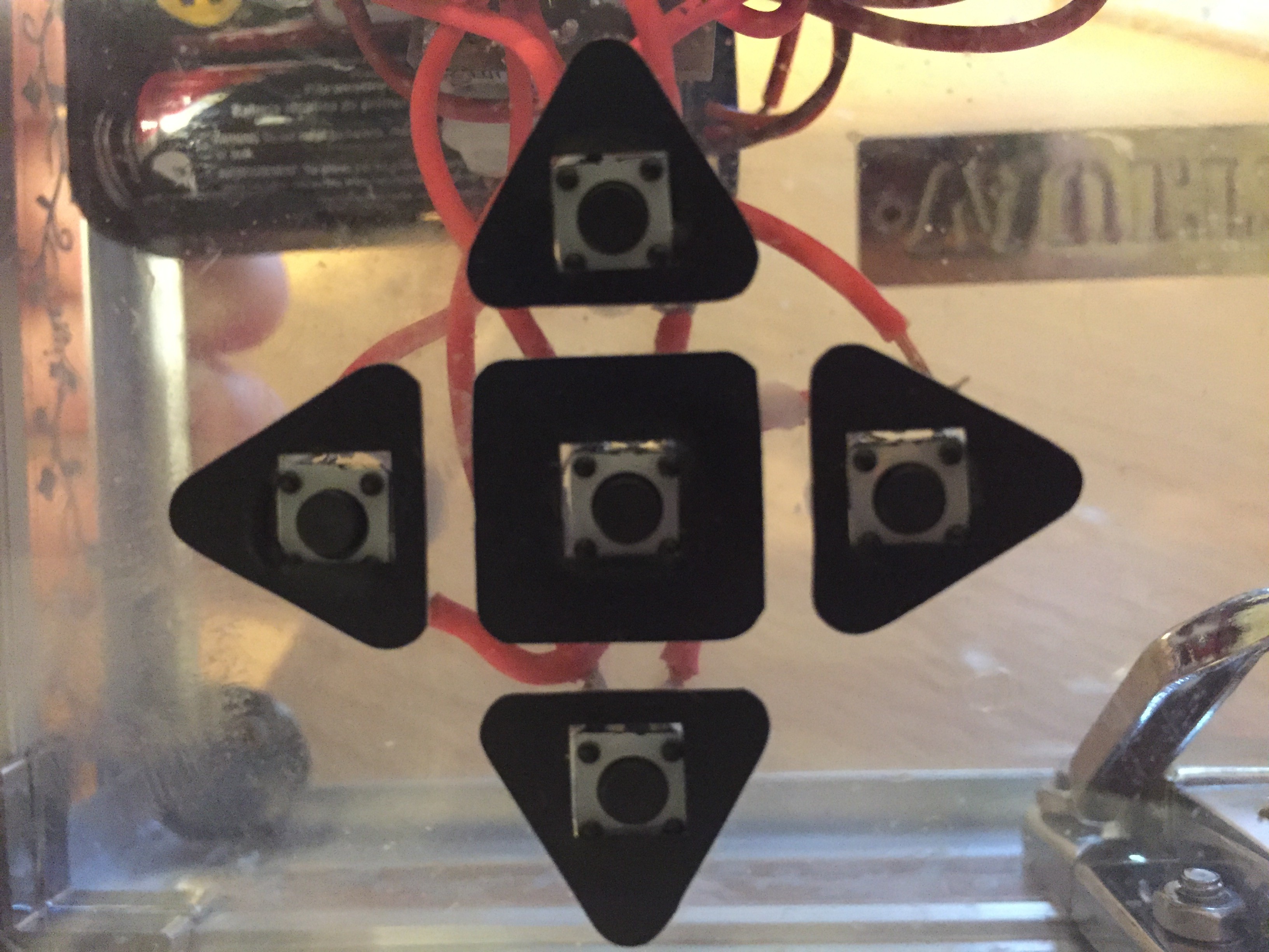
10/21/2015 at 06:15 • 0 commentsI first tried to create a touch interface, but as it turns out, that is only easy if your project is connected to ground, but since this project uses batteries, it does not have a ground, and thus it is much more complicated. Advanced circuitry would be required, which would not only increase the complexity of the design, but also the cost. The cheapest buttons I could find are those PCB tactile buttons (7 cents). I drilled some holes in the face of the box, pushed them in, and soldered them.
![]()
My wife added some stickers using her vinyl cutting machine. I tried super gluing these buttons in place at one point, but that was a really bad idea because the glue ended up seeping into the buttons and causing them to stop working. That was actually a disaster. I had to stay up late the night before my wedding and replace all of the tact buttons because I had just glued them the night before the wedding. (I swear I will never glue a tact button again!) Anyway so these are just held into place via friction, and that actually worked just fine. No glue necessary.
![]()
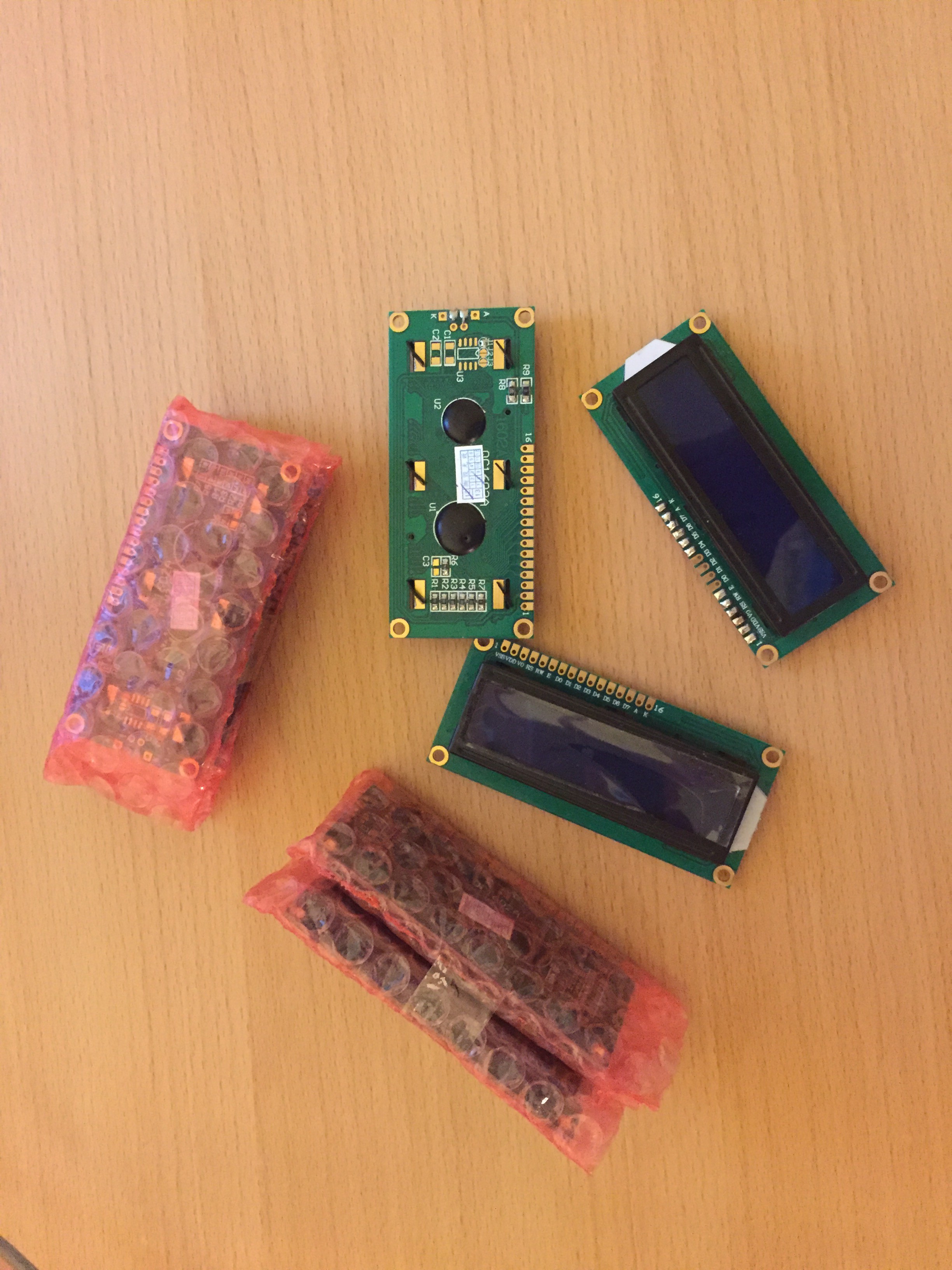
Here are the LCD displays that I got for $2.10 a piece:
![]()
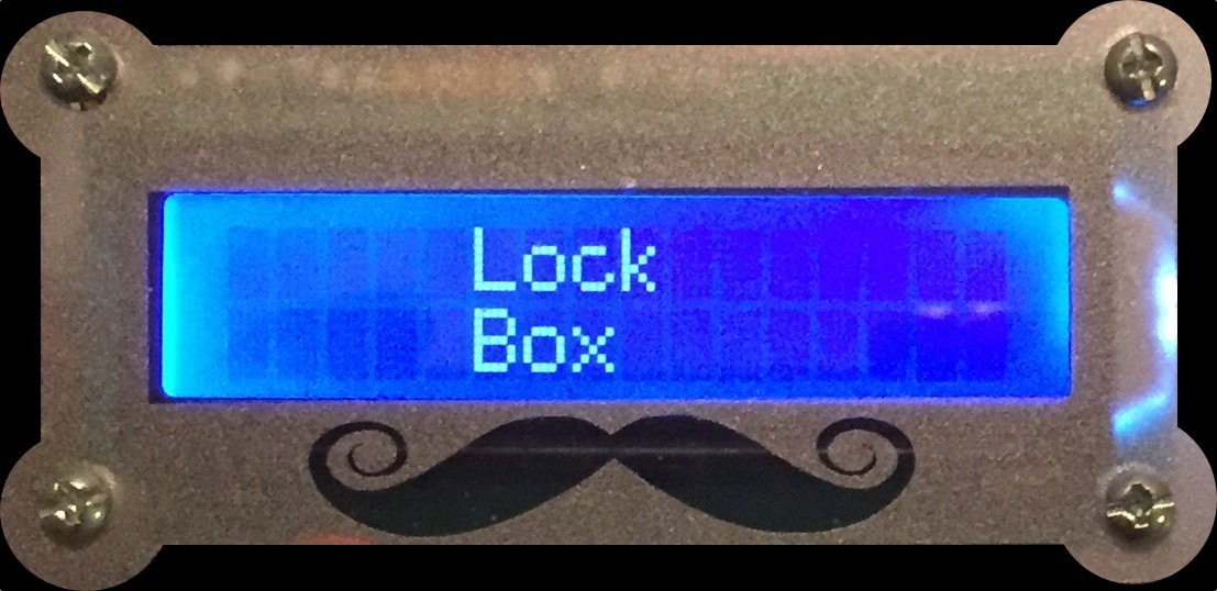
I drilled 4 screw holes and mounted the display inside the box. My wife created this nice moustache sticker to make it look classy:
![]()
-
The Microcontroller
10/21/2015 at 03:46 • 0 commentsI looked around to try to find the cheapest option for an Arduino microcontroller. I found one called RBBB (Really Bare Bones Board). I figured out that if I bought the PCBs and components separately, I would end up spending $7.24 per lock box.
![]()
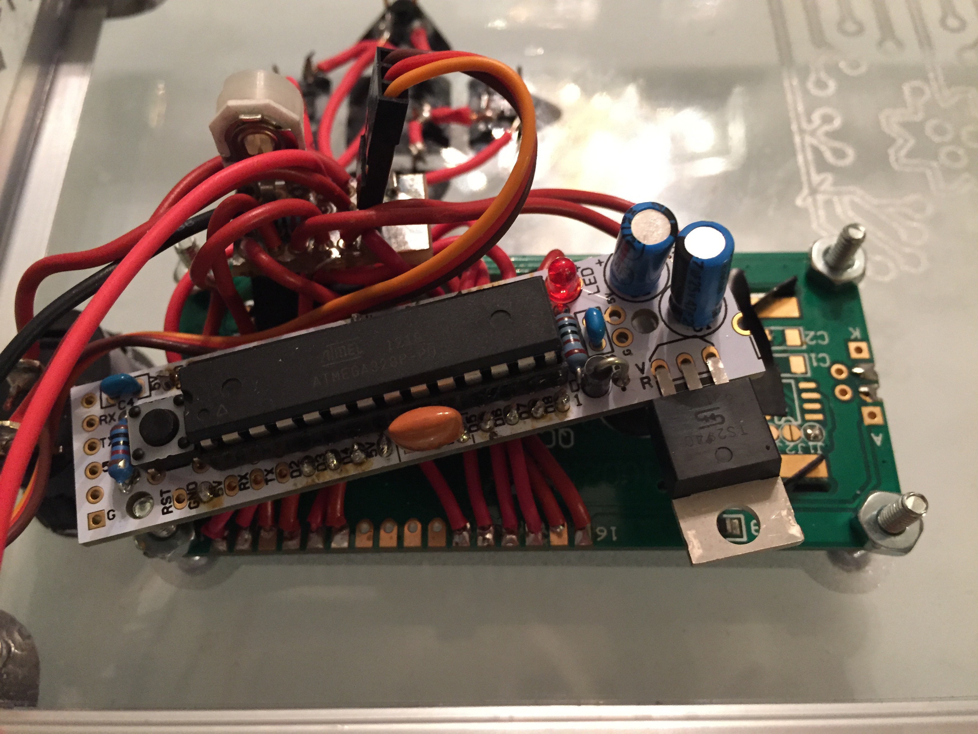
I omitted some unnecessary parts of RBBB to save cost, flashed the bootloader myself, and wired it directly to the back of the LCD module like so. Also, it's hard to see in the photo, but I had to add small piece of protoboard to help with some of the wiring, and also to add a trimmer to adjust the LCD backlight.
![]()
-
The Locking Mechanism
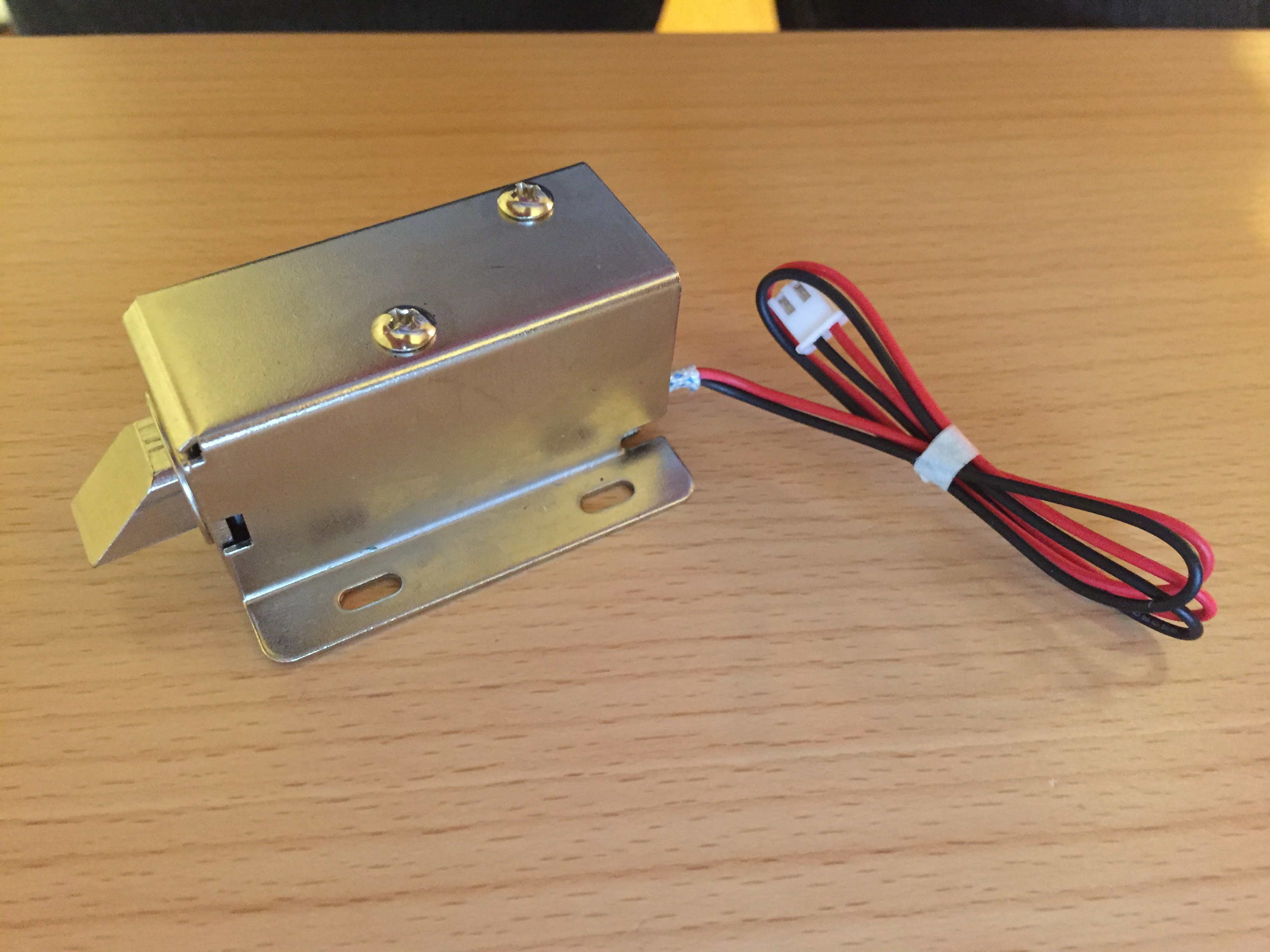
10/21/2015 at 03:10 • 0 commentsThe most important part of the lockbox is, of course, the locking mechanism. I thought of using a solenoid like this one, but they are too expensive for the number of boxes that I needed to make.
![]()
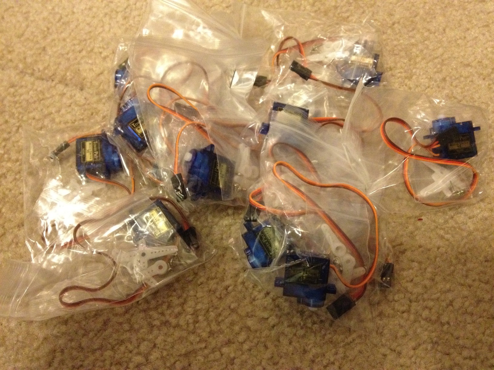
I tried googling for some ideas for a locking mechanism, and came across a reverse geocaching box which was invented by Mikal Hart (whom I didn't know at the time, but I later became friends with coincidentally for unrelated reasons). He used a hobby servo. I found some cheap servos on alibaba for $2.45 each.
![]()
These are the worst Chinese knockoff servos ever. Strangely they don't actually function like normal servos. They are either at 0 degrees, or 180 degrees. No in-between. That's all I needed anyway, and they were super cheap, so I'm not complaining.
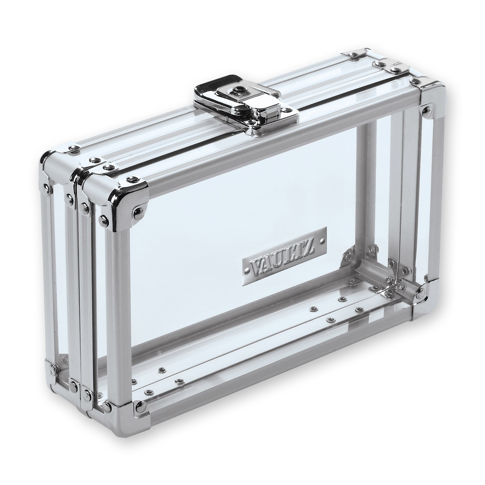
I ended up going with this cool see-through pencil box by vaultz because:
A) It looks nice.
B) I like the idea of being able to see whats going on inside while trying to open it.
C) It has a spring based latch mechanism that can be moved to the inside of the box and controlled by the servo (one of my friend's ideas).
This box was actually the most expensive item on the BOM clocking in at $9.99!![]()
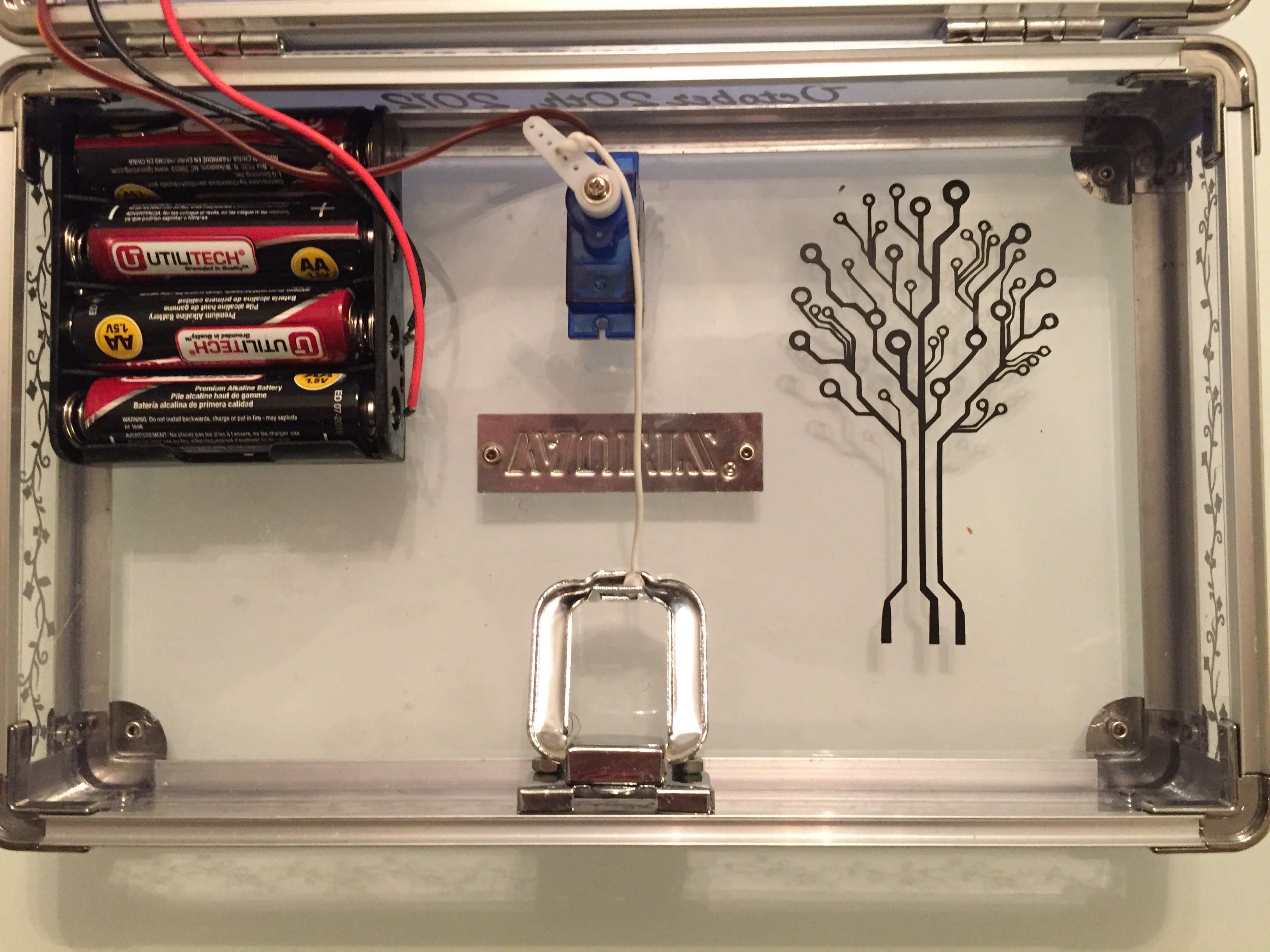
Here is a picture of the locking mechanism. The latch was removed and placed on the inside of the box. The servo was superglued on the inside of the box. An electrical wire was used to connect the horn of the servo to the latch to pull it open. When servo rotates back 180 degrees, the spring inside the latch pulls the latch closed.
![]()
Lock Box
This box can only be opened after correctly answering the questions that it was programmed with.
 Nathan Peterson