-
Meassuring the current consumption
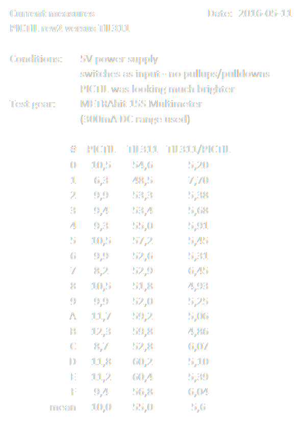
05/11/2016 at 20:57 • 1 commentI did some current measurement of PICTIL rev2 compared to a original TIL311. As also seen in the table I powered both from 5V using the same breadboard circuit. The PICTIL was also much brighter (as far as the human eye is an instrument for that). Another point is that I do only have one original TIL311 (datacode: 9243 made in Korea) I do not know whether this one is typical for all. The used current range (300mA) was the lowest on my multimeter. The unit for the currents is mA. The last columns is the current of the original divided by the value of PICTIL.
![]()
As you can see the PICTIL rev2 is much better than the TIL311 in terms of power consumption. On average the PICTIL consumes only 10mA! When dimming the PICTIL to archive the same brightness as the TIL311 the results should be even better.
Some added Note:
I repeated this measurement today with a other meter. According to the specs the Fluke 8040A is better. It has also a 20mA range, but this meter is much older and as far I know was never calibrated. (The METRAhit used before was last calibrated in December 2011). But never the less The measurements were very similar most times about 1,2mA higher for both PICTIL and TIL311. -
rev2 is working!
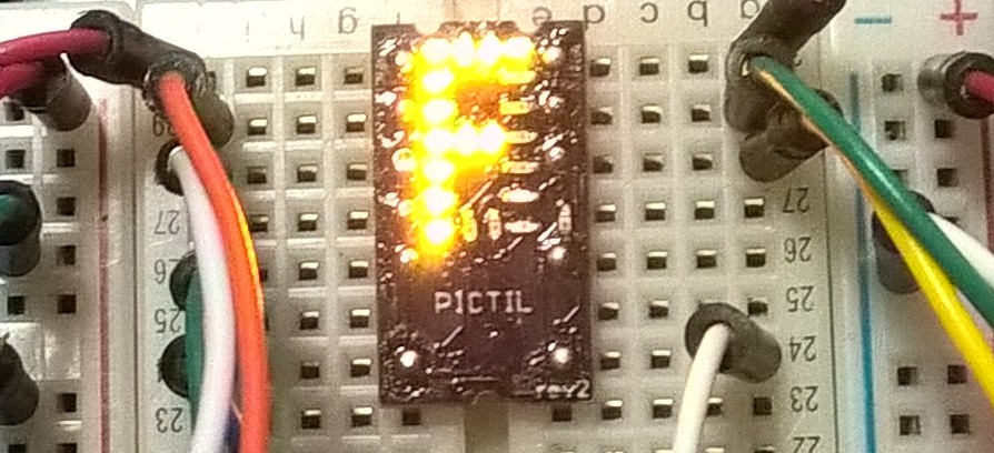
05/11/2016 at 19:59 • 7 commentsToday the missing parts for finishing rev2 arrived. And it's also working. Also the blank circuit is working! Here a first image. I will take better ones soon.
![]()
The changed firmware is now also available in the bit bucket repository. So in combination with the link to the board at OSH park. Everyone with decent soldering skills can build his own. If you do that please post some pictures.
-
rev2 soldering - Part 1
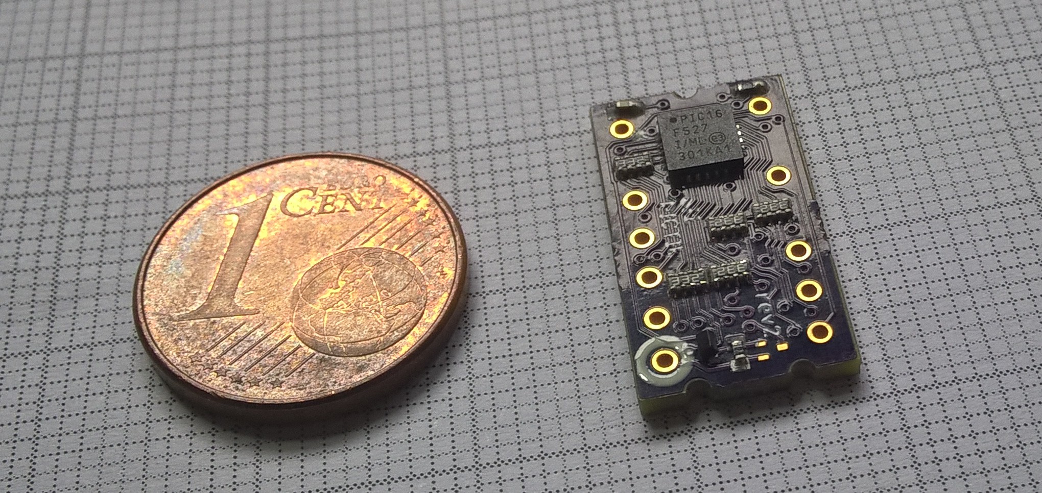
04/18/2016 at 15:31 • 0 commentsI did stated with the soldering of the first rev2 board. Now I have to wait on the missing transistor before soldering the other (the LED) side. The coin in the image has a diameter of 16.25mm/0.64''.
![]()
I am also not sure yet which LED color I will use. If you have a wish please leave a comment. I do have red, green, yellow, blue and white LEDs.
-
rev2 PCBs are in
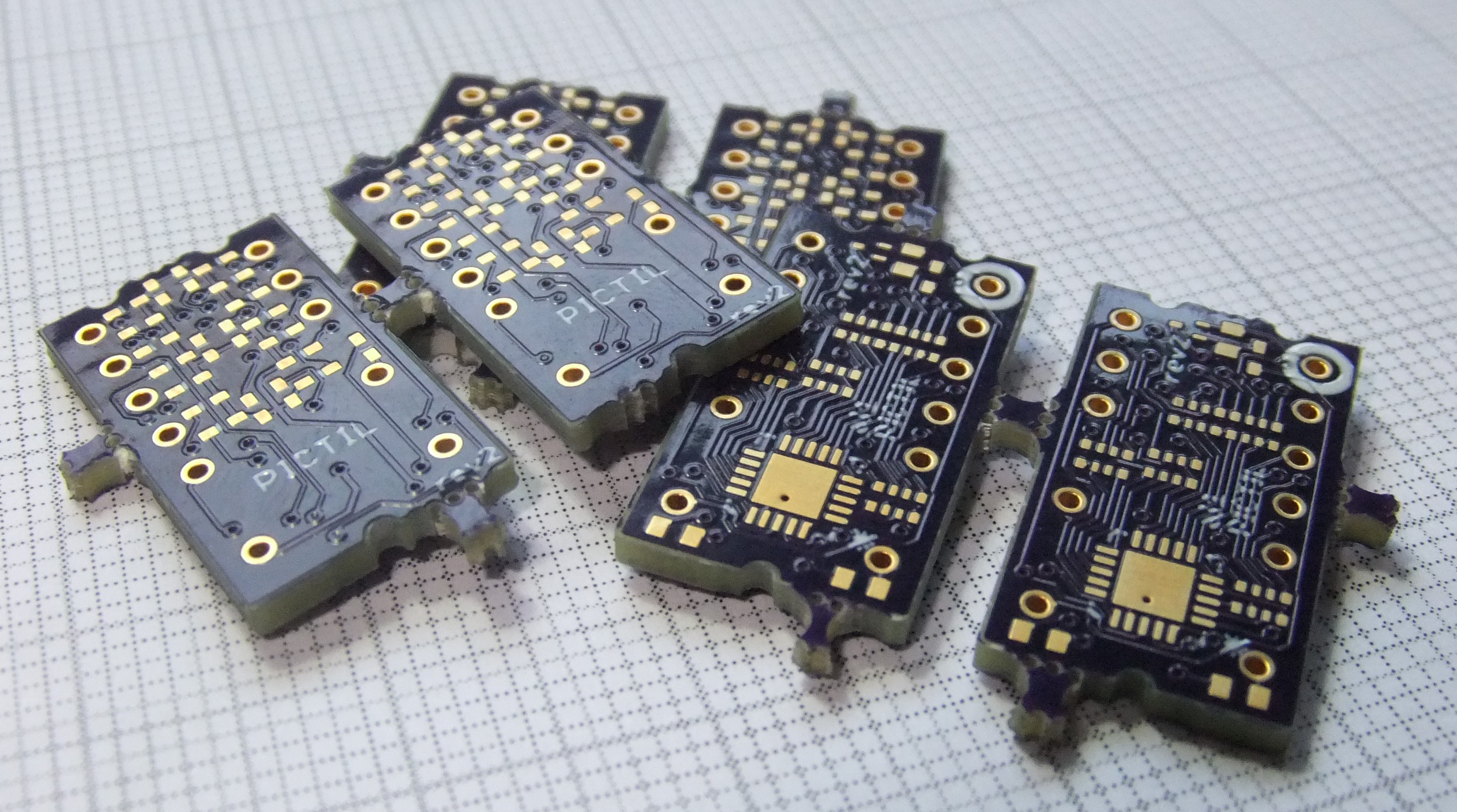
04/14/2016 at 17:23 • 4 commentsThe new rev2 PCBs did arrive from OSH park. I hope the p-fet bug is fixed now. I am still waiting on some parts (the new p-fet LEDs in not red). When I do have all parts I will solder one and take some more pictures.
If you want to get your own ones, here you can order the PCBs: https://oshpark.com/shared_projects/LDcRWFo1
Please Share some photos if you built one
-
update to rev2
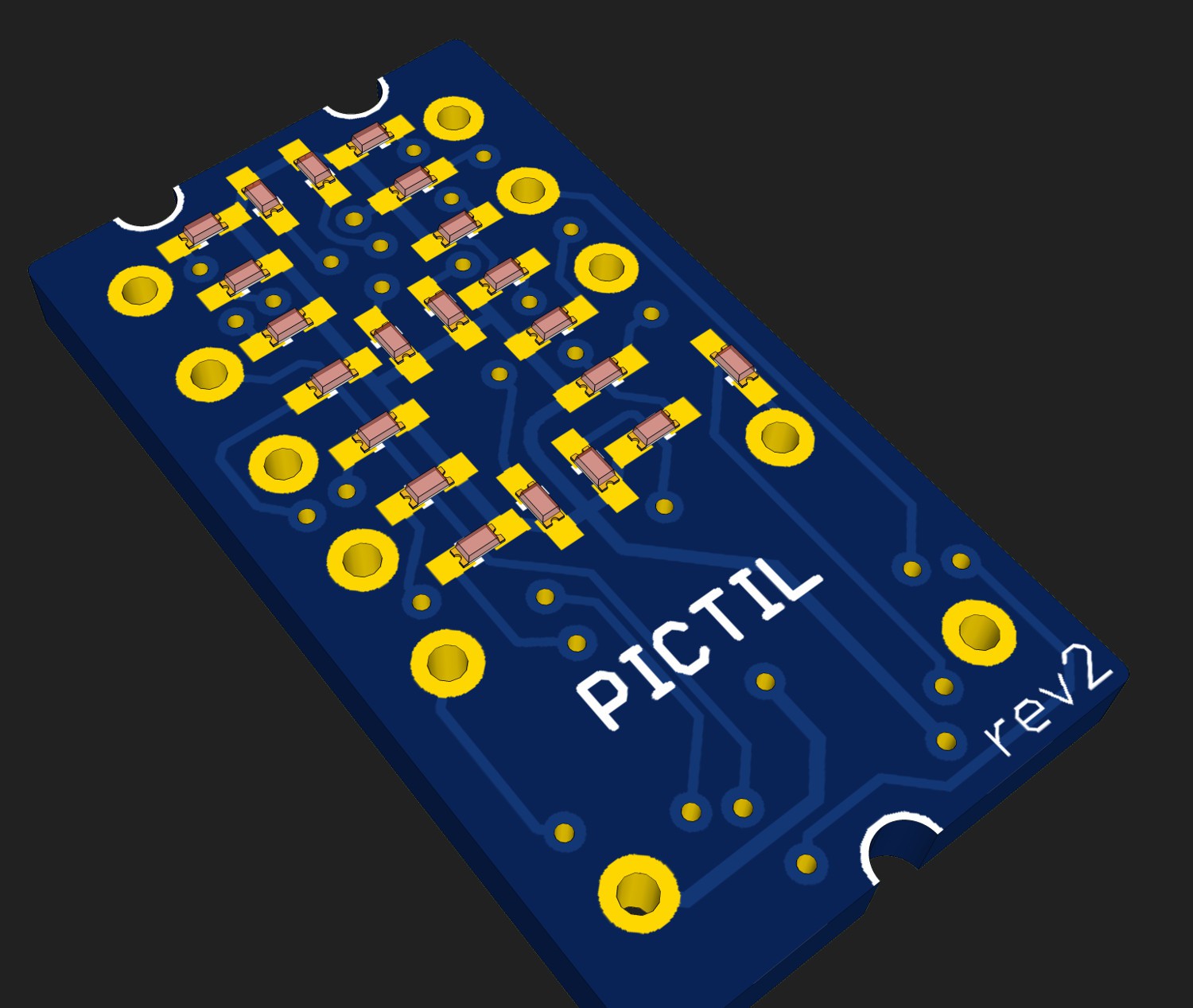
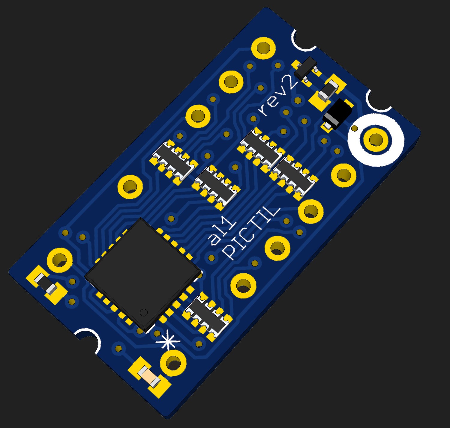
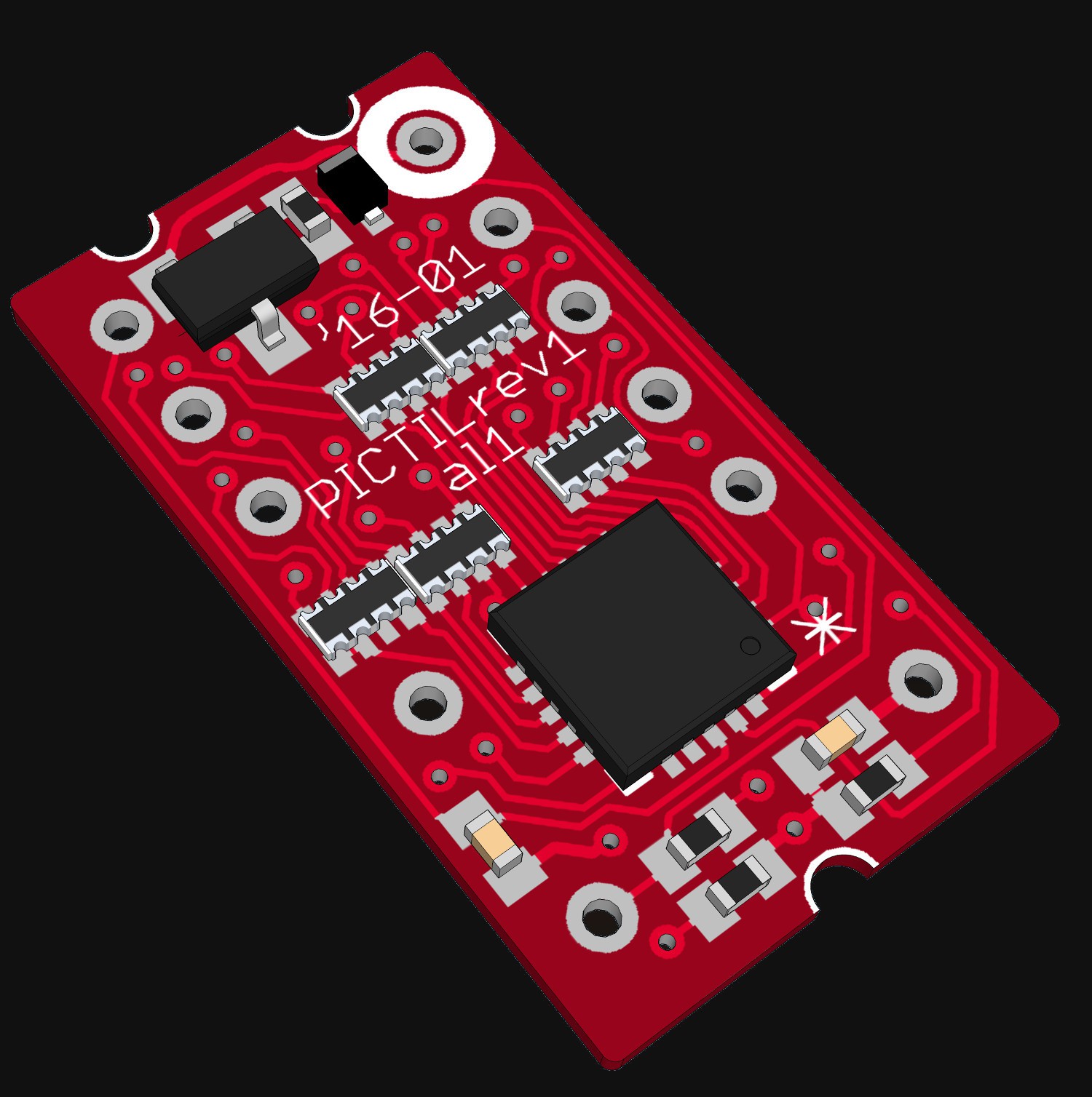
04/01/2016 at 16:31 • 9 commentsThere was still the mistake with the not working blank input in the last version. And I did not like that. Specially if looking for testing Tindie with this. So I did some rework on the PCB layout. Now I do think I did fixed that issue. Additional I did change the layout in a way to be inside more Manufacturer's specs. In rev1 I use 5mil Traces/Spaces with 12mil drills. No it is 6Mil/16mil with 13mil drills nad is now again producable by OSHpark (with was important for me to get cheaper and faster Prototypes in low quantity - 1,55$/3PCBs ). To get that I did throw out some unnecessary components and changed the mosfet package to SOT-723. Boards are ordered and should be arrive soon. Here are some renders:
![]()
![]()
-
more Pictures
03/14/2016 at 18:16 • 0 comments -
.gif time
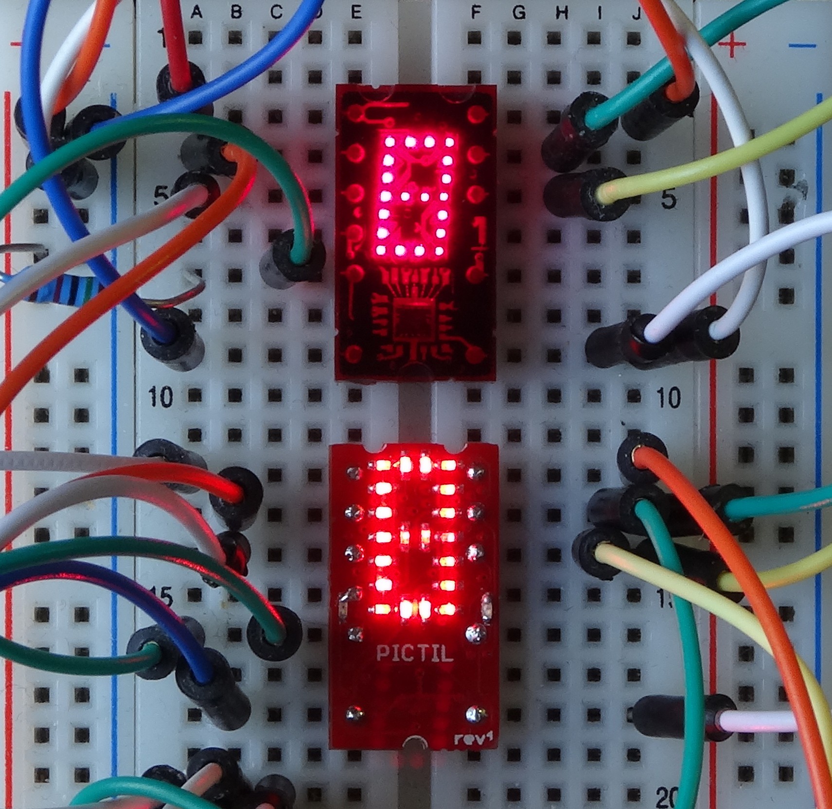
03/13/2016 at 18:50 • 4 commentsdid change the software. Now rev1 is also working correct. On the top is a original TIL311:
![]()
-
some soldering
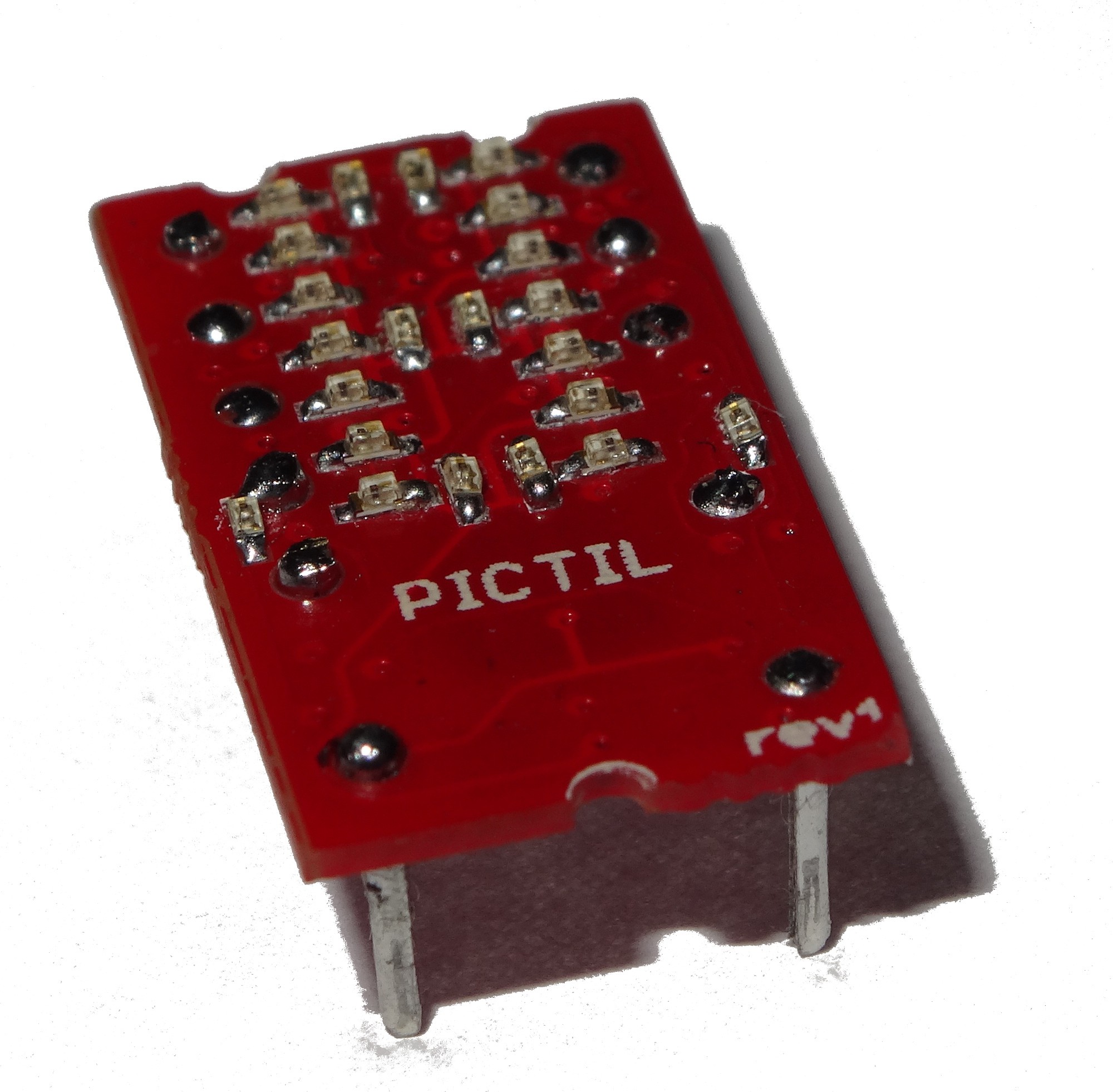
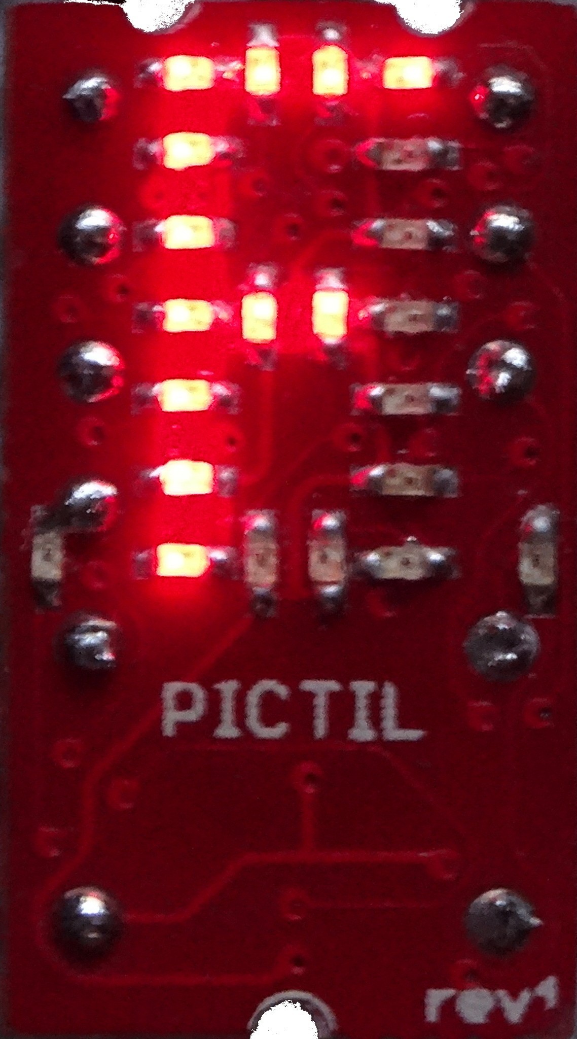
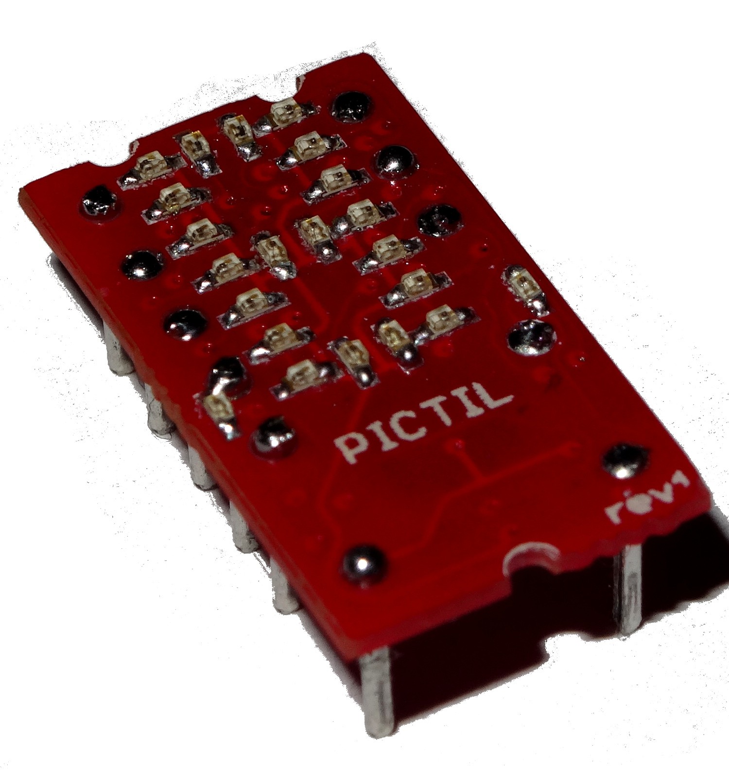
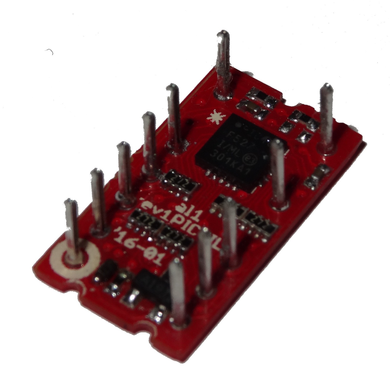
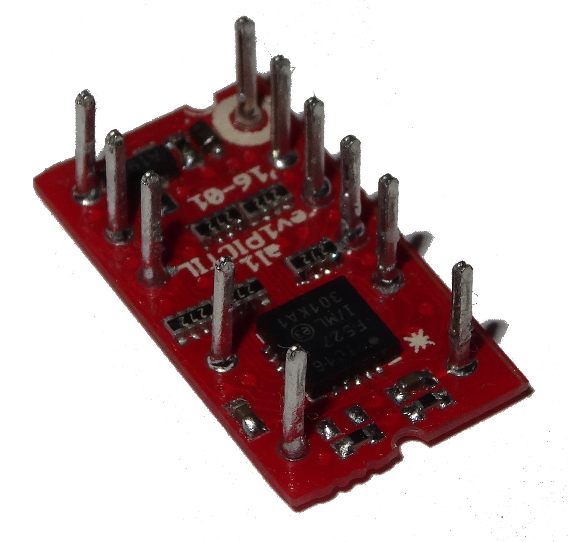
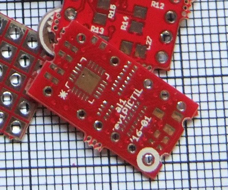
03/12/2016 at 20:55 • 3 commentssoldering ready. And it did also work (but I did not change the pin mapping in the code so no right numbers are shown). First some pictures:
This is the most extreme thing I soldered so far and is working.
Sadly I did not corrected the mistake in the schematic. I did wrote about that in a previous log. But that is only affect the BLANK pin.
The PCB is 0.6mm thick. The single resistors, capacitors and LEDs are 0402. The dimensions are now the same as the original TIL311 (I will take a side by side picture the next days).
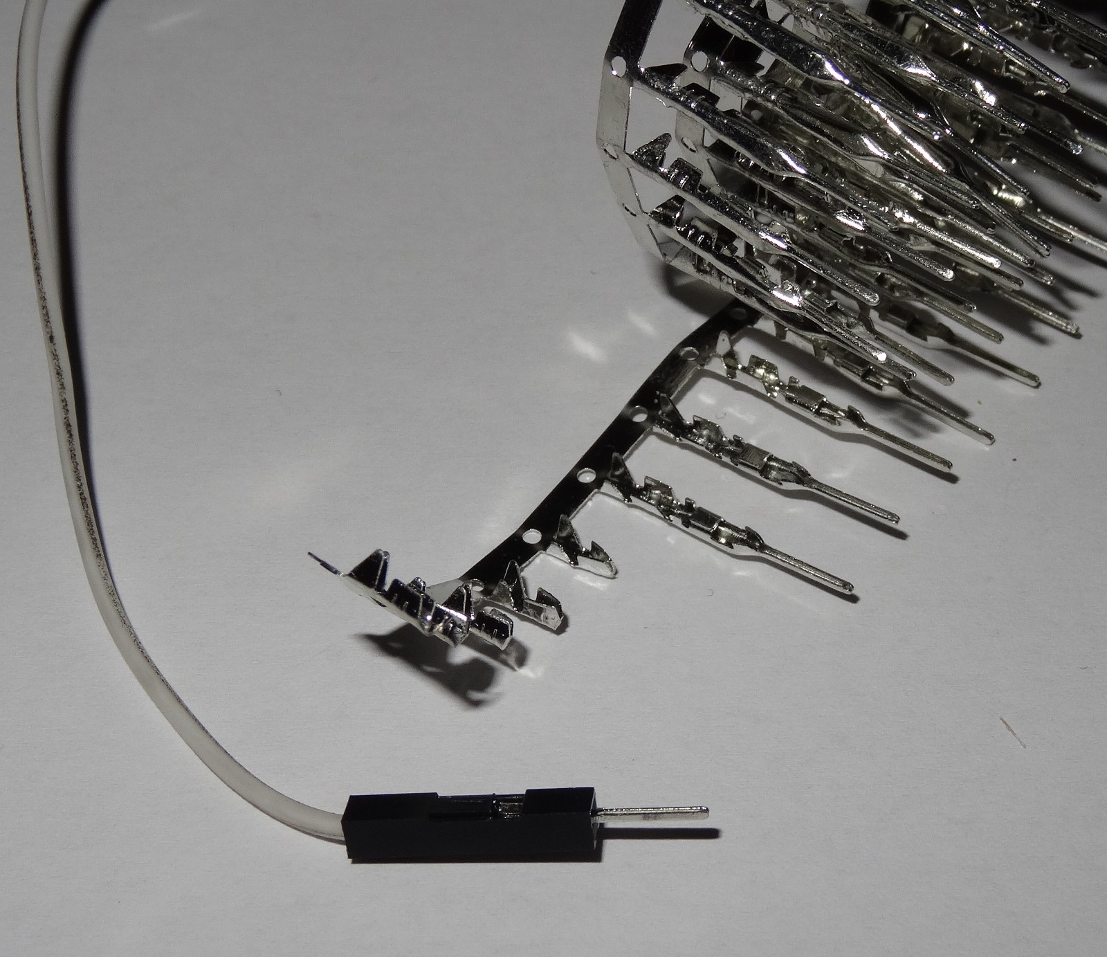
To the pins: There where some very good suggestions in the comments of a previous log. I do still like the idea of using nails. But I was to lazy to get them. So I did searched for substitute which I had available. I ended up with the pin of these wires:
After soldering the whole pin in I did cut of the crimp part of it. This came out good enough and is also not expensive (0.82€ / 100 pins).
Next I will update the software. This is needed because I changed the pin mapping of the LEDs.
-
rev1 PCB arrived
03/12/2016 at 16:16 • 2 commentsThe PCB from the last post was part of a small panel. If you follow me on Twitter, I did post a photo on the whole panel there.
Next task: some extreme soldering. I did also found a low budget solution (not the brass nails) for the pins. I will write something about that when its soldered and ready. I think I will do the soldering today. There are also some changes in the software needed, but only some pin changes.
-
rev1
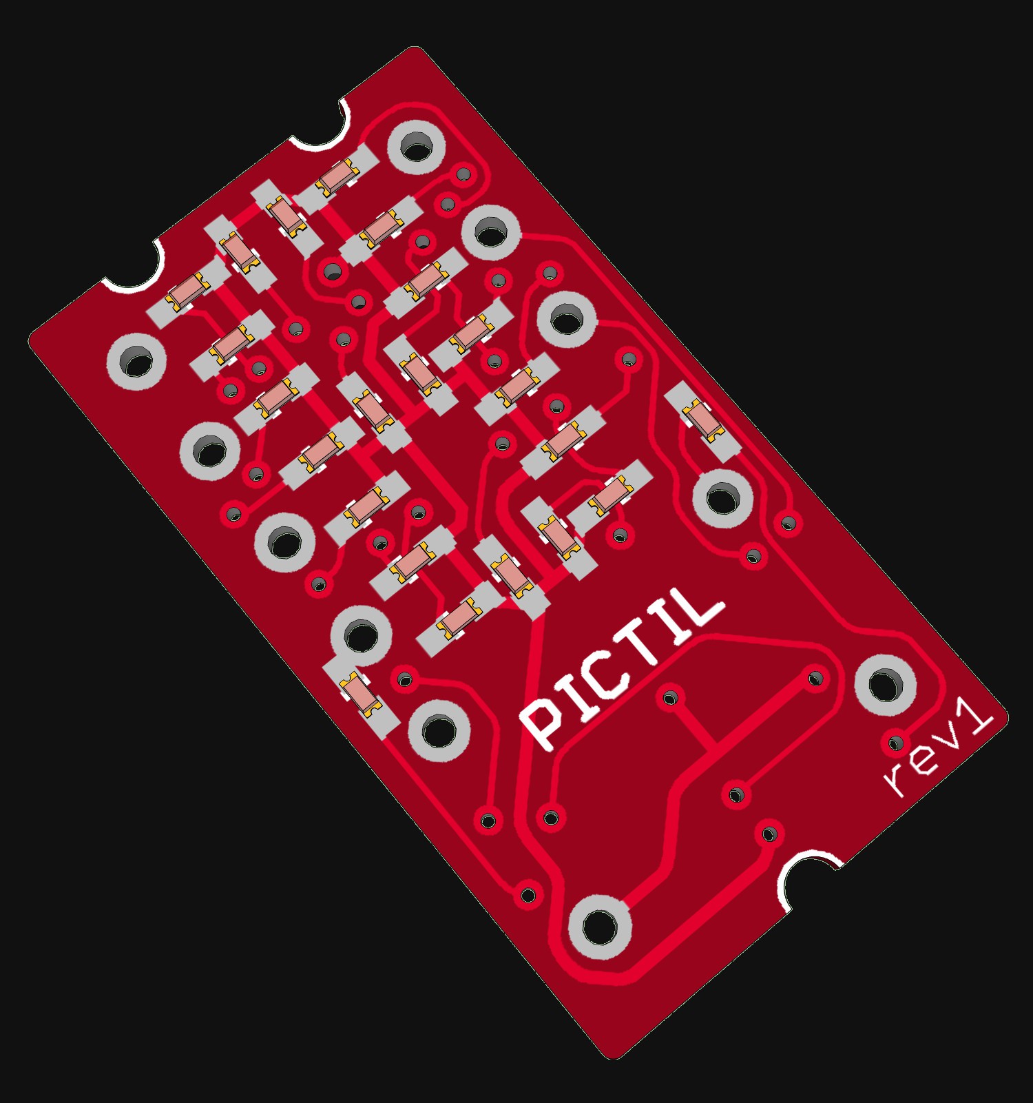
01/24/2016 at 21:14 • 7 commentsI did made some improvements in the design. first I did add holes for small THT pins ( pins like used in #OSHChip V1.0 would be nice). Unlucky there is no source for small pins. but normal thin hard wire could also work. The numbers of LEDs did also increase. Now there is the same number of LED like in the original TIL311. all parts beside LEDs are now hidden on the back. The down side of this is that this design uses 5mil traces and 12 mill holes, which is smaller then OSH-park's specs. But some of the Chinese manufacturers should deal with that.
![]()
![]()
 Alex
Alex