0%
0%
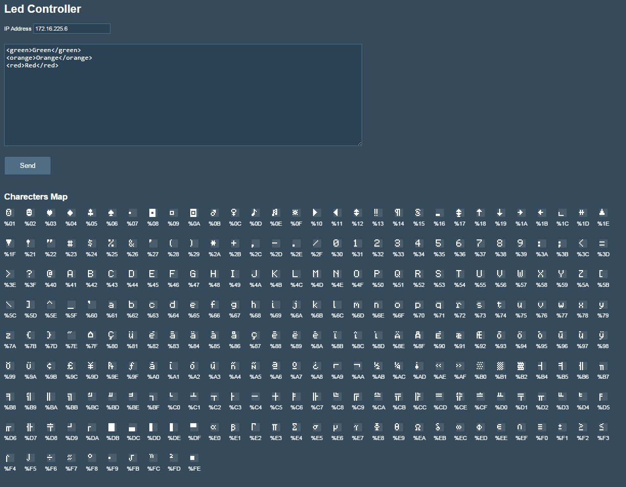
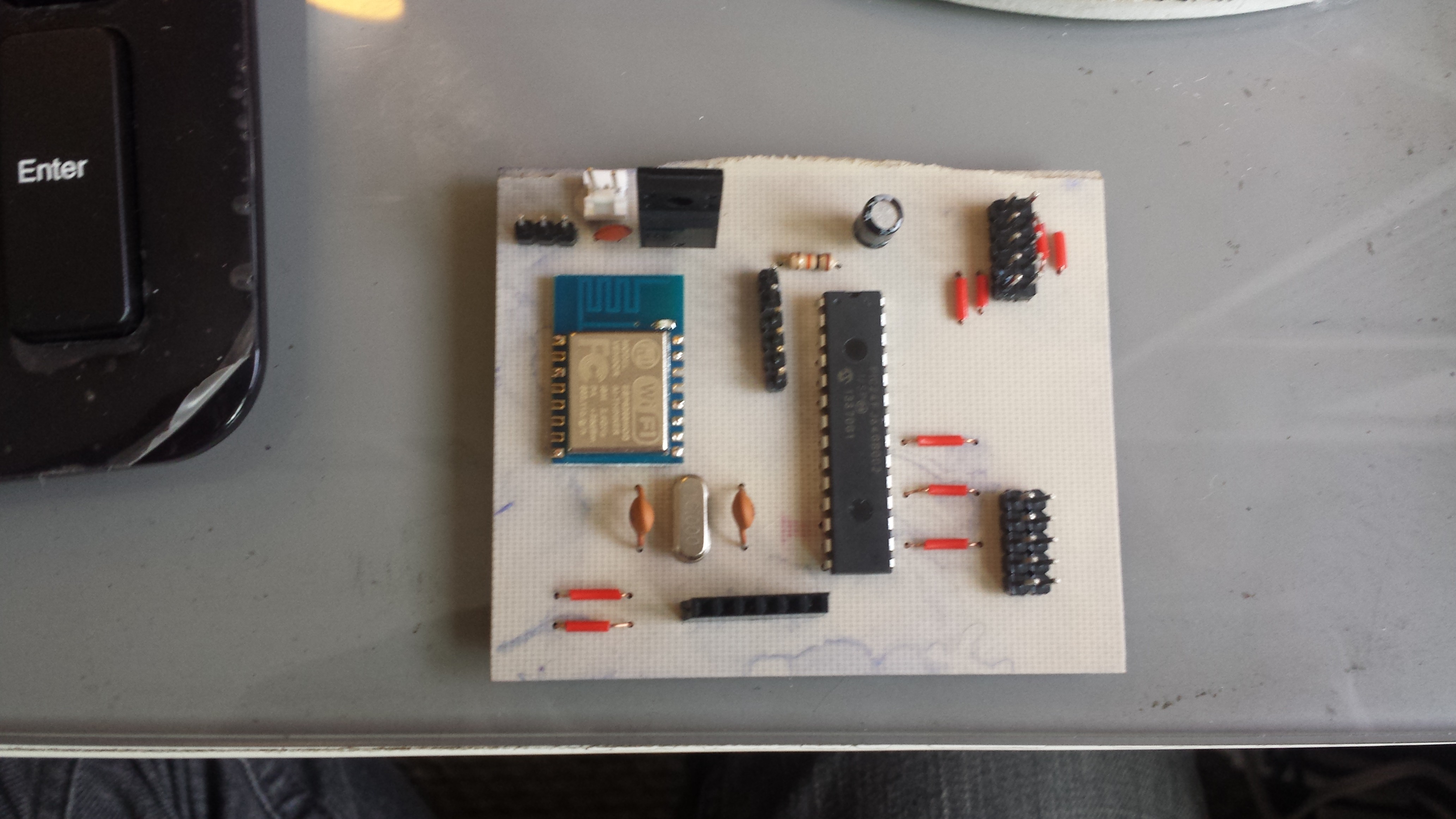
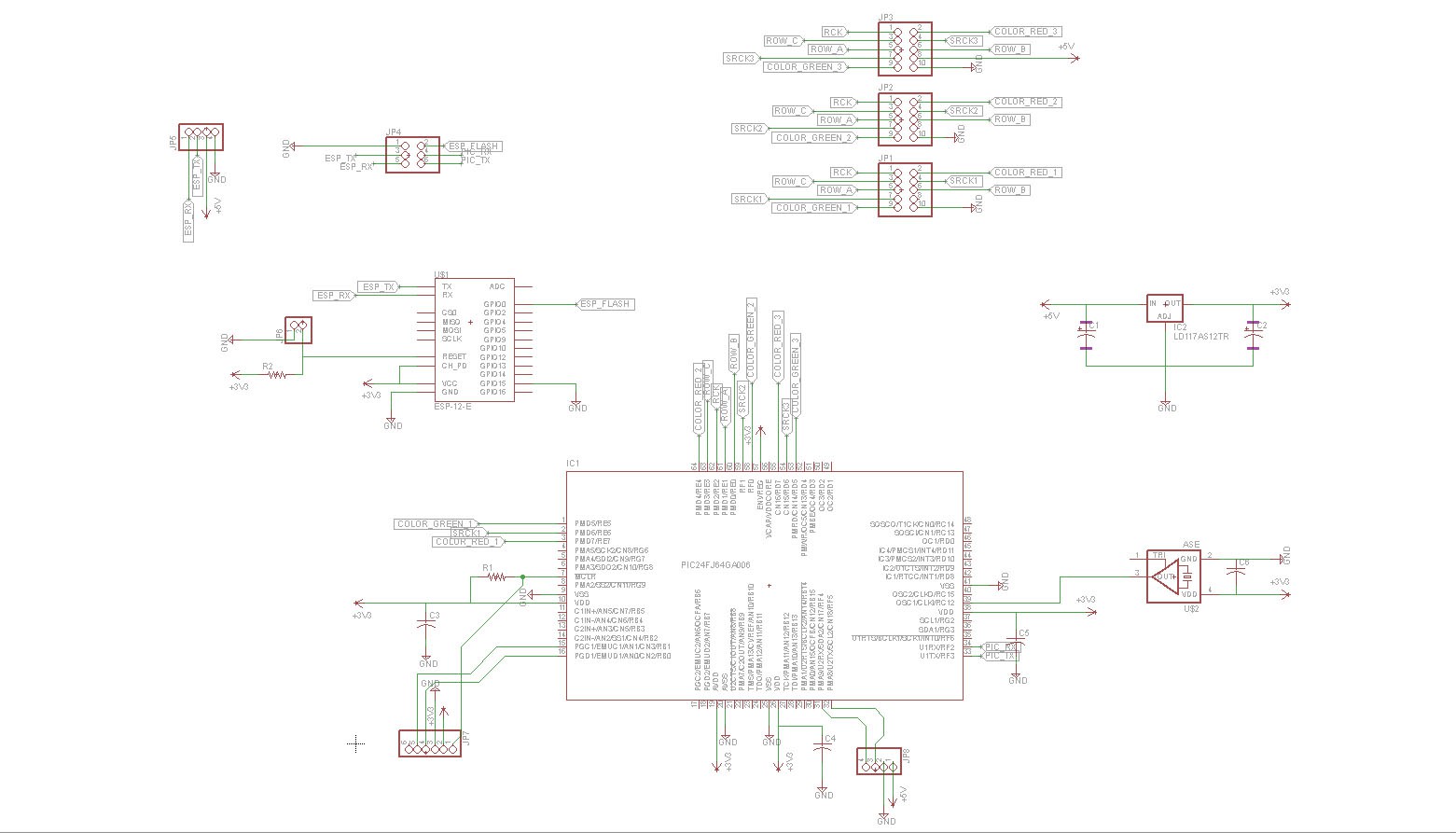
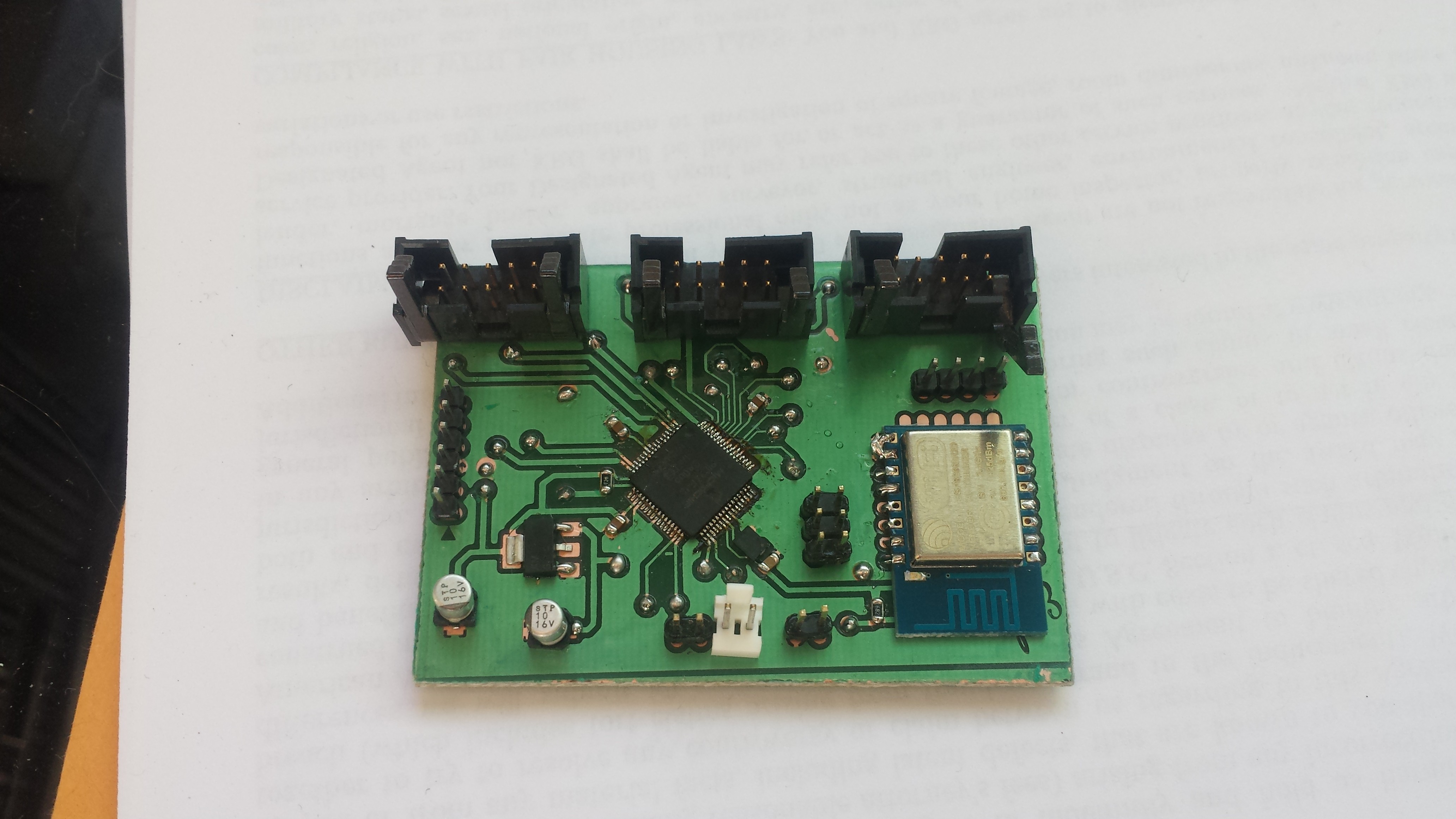
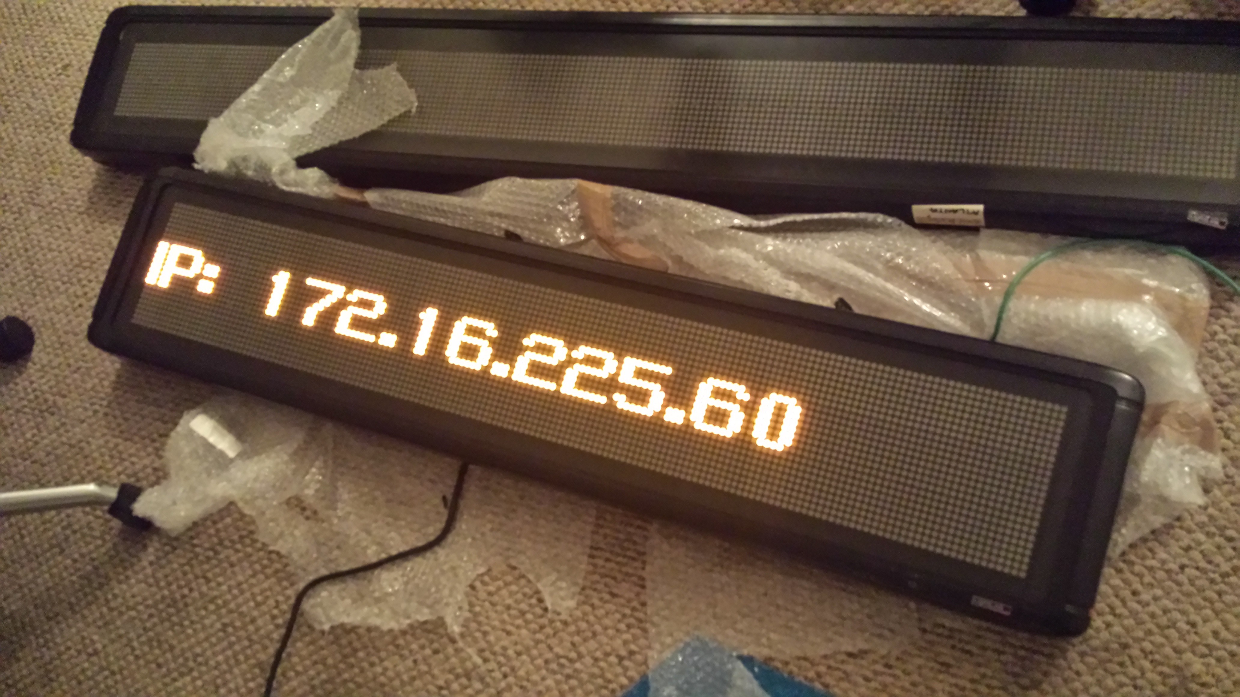
LED Matrix Controller
Replacing an old Lightlink/Inova FPGA Scrolling LED board controller with PIC24F + ESP8266
 Yadid Ramot
Become a Hackaday.io member
Already have an account? Log in.
Just one more thing
To make the experience fit your profile, pick a username and tell us what interests you.
Pick an awesome username
hackaday.io/
Your profile's URL: hackaday.io/username. Max 25 alphanumeric characters.
Pick a few interests
Projects that share your interests
People that share your interests


 zakqwy
 Sree Harsha Angara
 joshua.vader
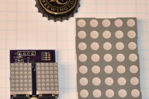
 Bharbour