Yadid Ramot
-
Slack #Support
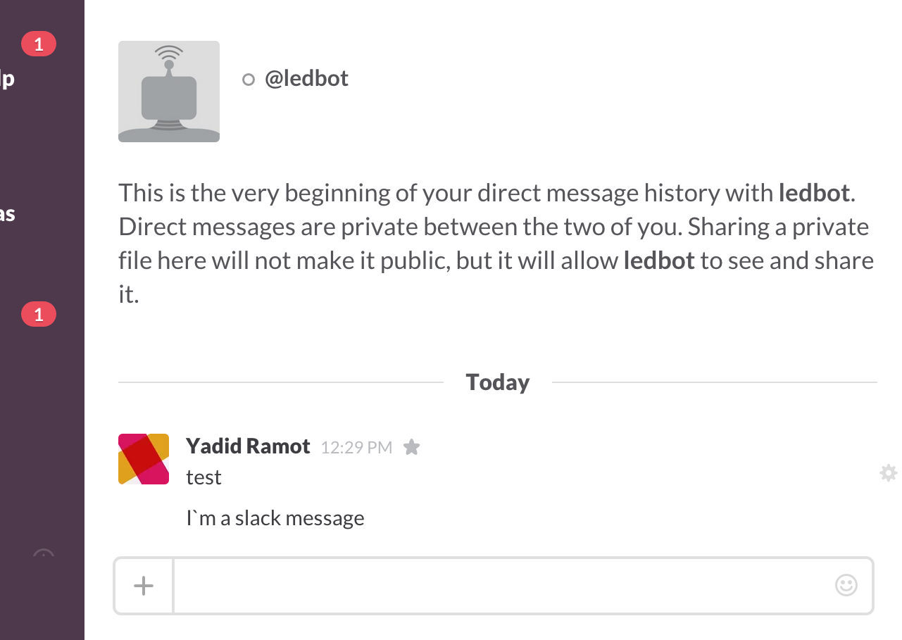
11/09/2015 at 22:23 • 0 commentsJust finished a quick Slack/NodeJS process that`ll update the LED sign with slack messages.
What it does is just listen to incoming messages to the @ledbot user, clear the display (/led/clear) and send the new message to the display (/led/print)
Code is available on GitHub - https://github.com/eyadid/esp-led-controller/tree/master/SlackBot
![]()
![]()
-
ESP API + Interface
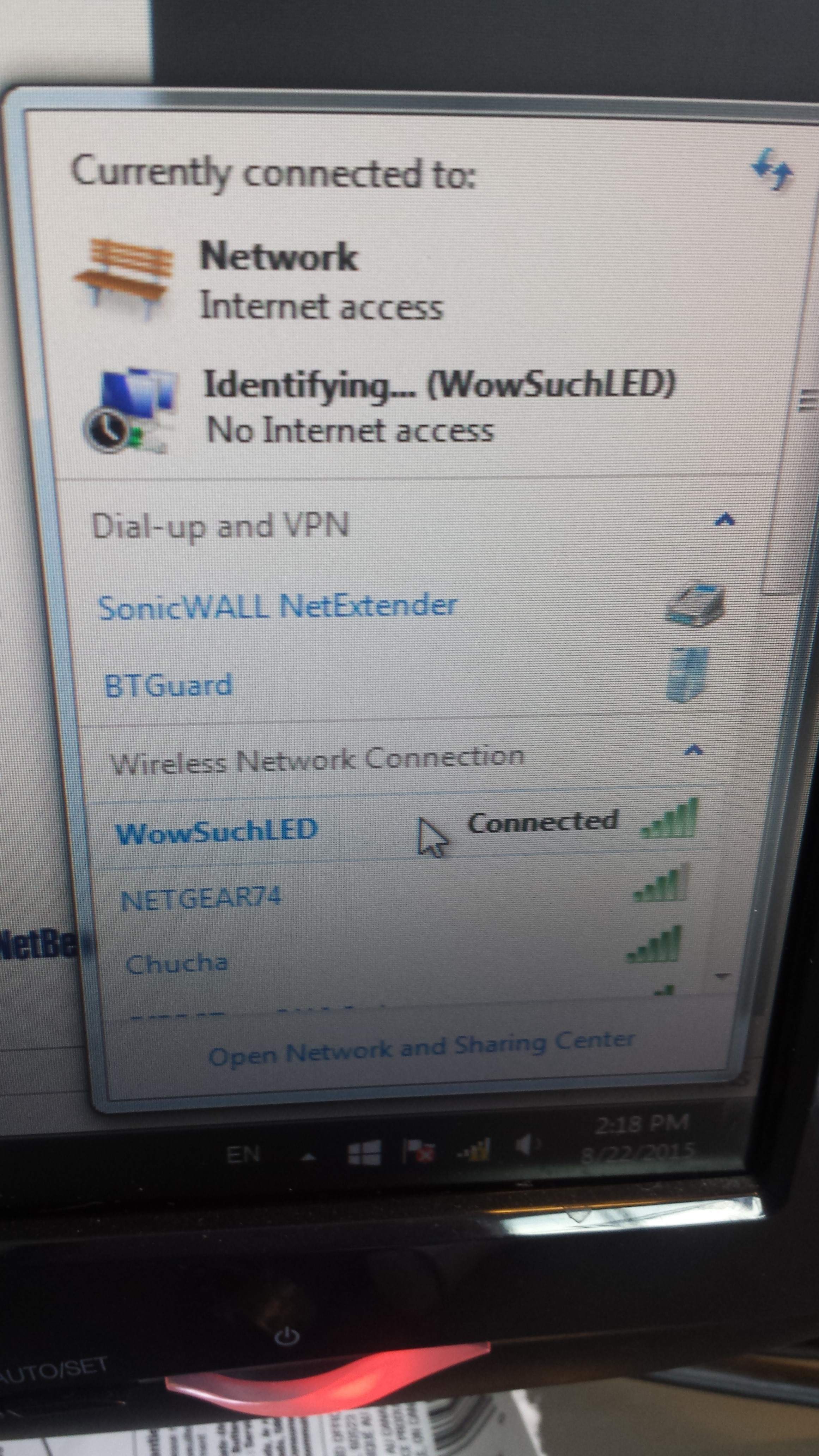
11/08/2015 at 22:17 • 0 commentsI finished setting up a few API end-points that`ll let me configure the WIFI on the ESP (a separate project on the subject is in the making)
The esp have 4 utility end points -
- /api/status - displays the status of the device
- /api/set-wifi?ssid=<ssid>&psk=<psk> - tells the device to connect to this network
- /api/set-ap?ssid=<ssid>&psk=<psk> - tells the device to setup a new AP
- /api/reboot - reboot the device
The ESP also have 3 end points to control the LED sign -
- /led/set-color?color=< GREEN | ORANGE | RED | BLINKING_GREEN | BLINKING_ORANGE | BLINKING_RED > - Set current color
- /led/clear - Clear the display
- /led/print?text=< MESSAGE > - Print a message
- /led/align - Currently N/A - Align current row
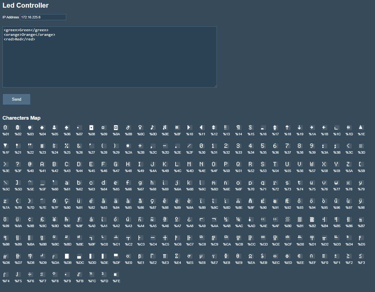
Iv'e also create a simple HTML page that`ll let me send commands to the board.
The commands are set with a simple XML format. Each row in the text-area corresponds with a row on the display.
The XML supports the following tags :
- Color Tag: <green | red | orange | blinkgreen | blinkred | blinkorange >
Example: <green>Text</green> - Space Tag: <#>
Example: <16> - will create a space of 16 pixels
![]()
![]()
-
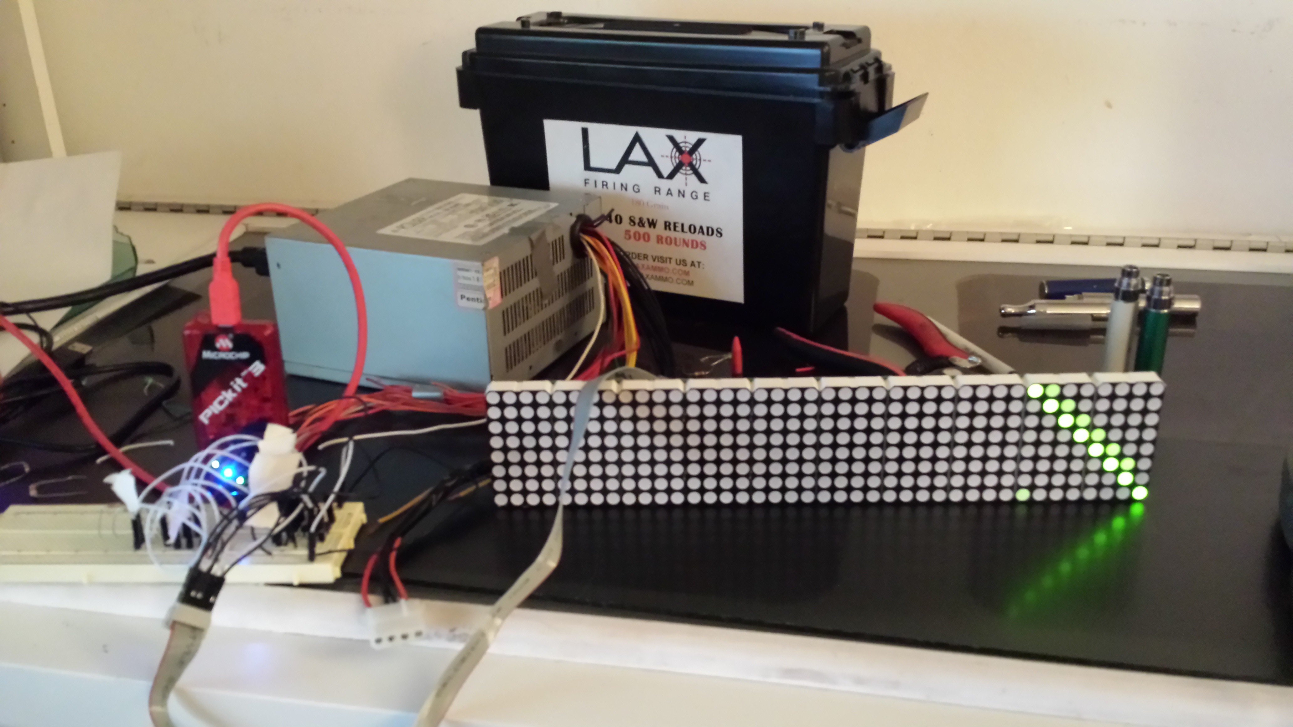
PIC Controller Board
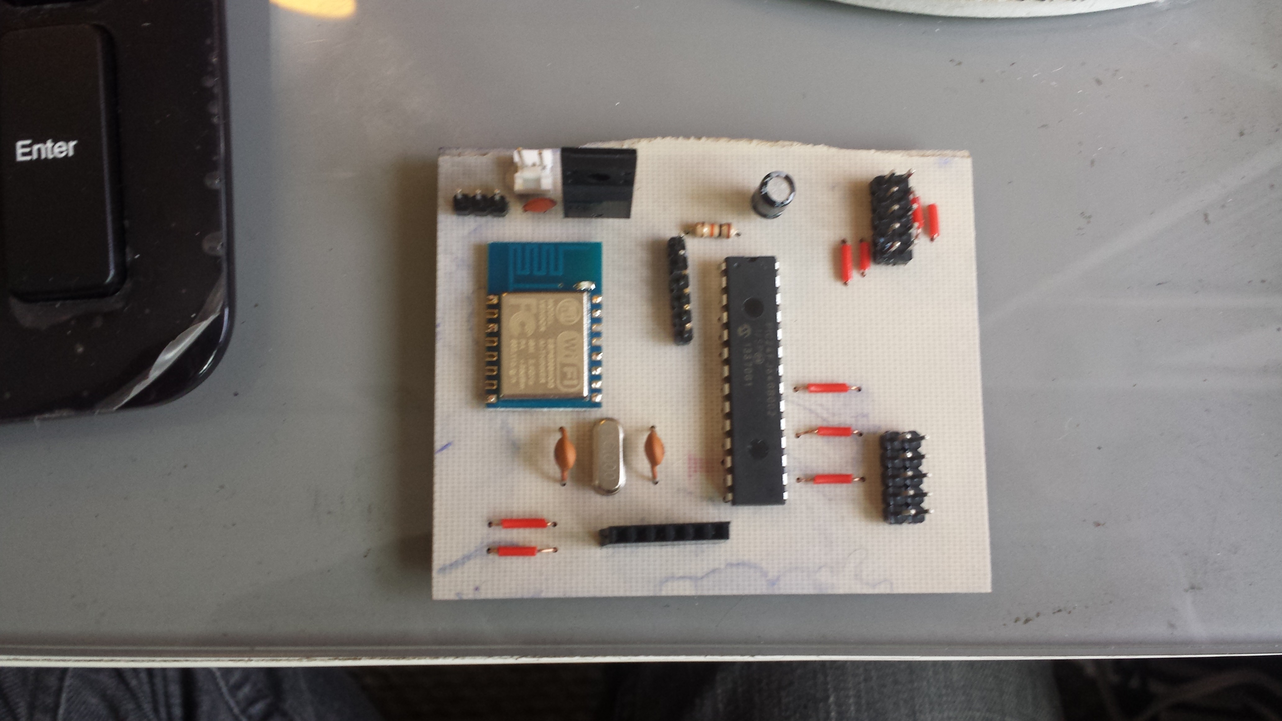
11/08/2015 at 21:30 • 0 comments![]()
I managed to get my first version of the board working using a PIC24GB002.
For this board, PIC was communicating directly with the AT commands of the ESP (sending AT's and parsing response). the 3 end-points i created were :
/led/clear
/led/print?text=<TEXT>
/led/set-color?color=RED|GREEN|ORANGE
The problems with this board are
- Writing and parsing AT commands on the PIC cost me with precious CPU cycles, which in turn caused the display to flicker every time i sent a command to the ESP over the network. The PIC had a 16mhz oscillator connected to it but even with 16mhz the screen was still flickering ever once in a while when i typed a new message
- PIC24GB002 didnt have enough IO pins to support the 160x24 display (3 IOs for each row + 4 shared across rows = 13 IOs pins needed)
Iv'e decided that for the next test board i will -
- Use a larger PIC - PIC24FJGA006 which have more than enough pins to support the larger 160x24 display
- Remove the parsing and REST request processing from the PIC and move it to the ESP
- as a 'bonus' - i`m gonna to replace the old 16mhz oscillator with a new 20mhz one - which will hopefully eliminate the flickering completely
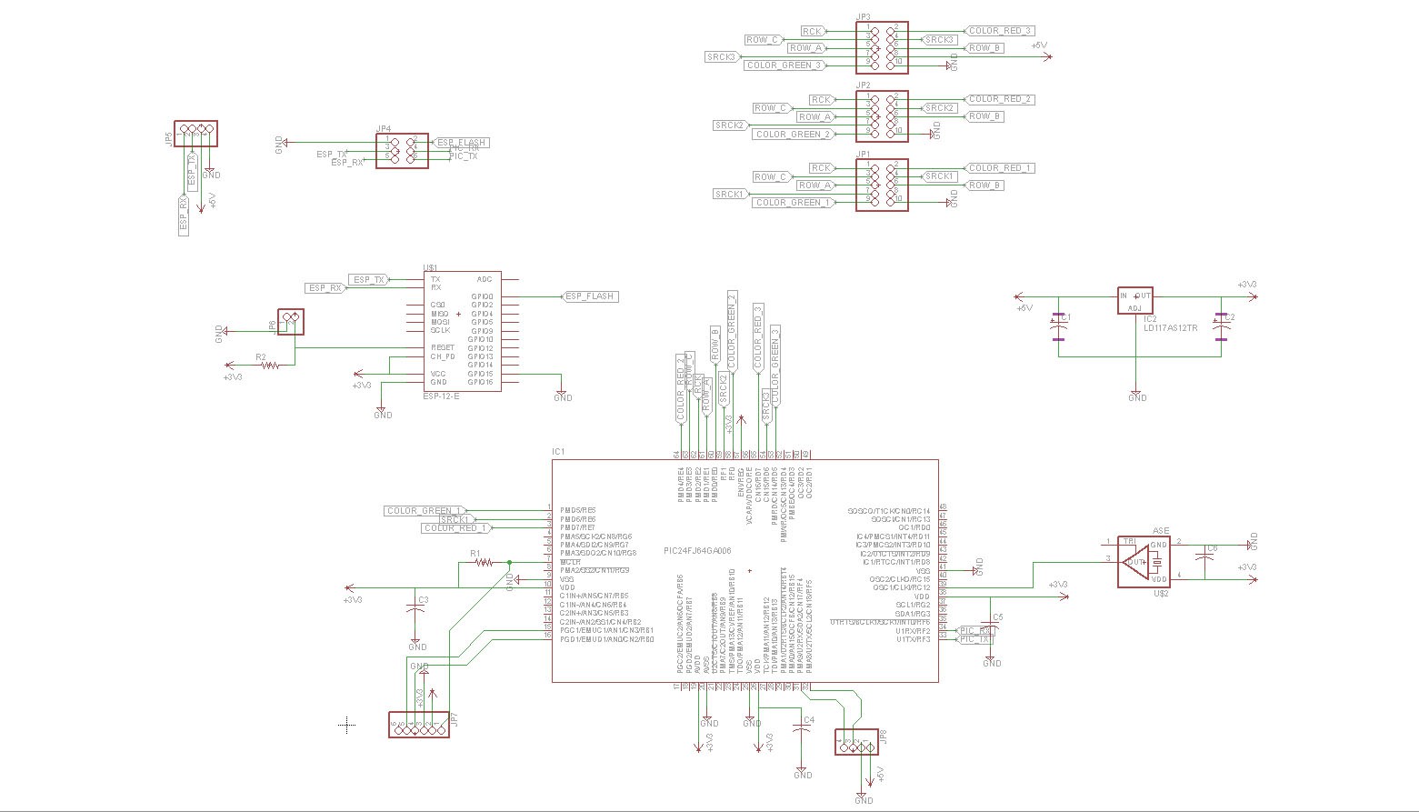
I came up with this design -
![]()
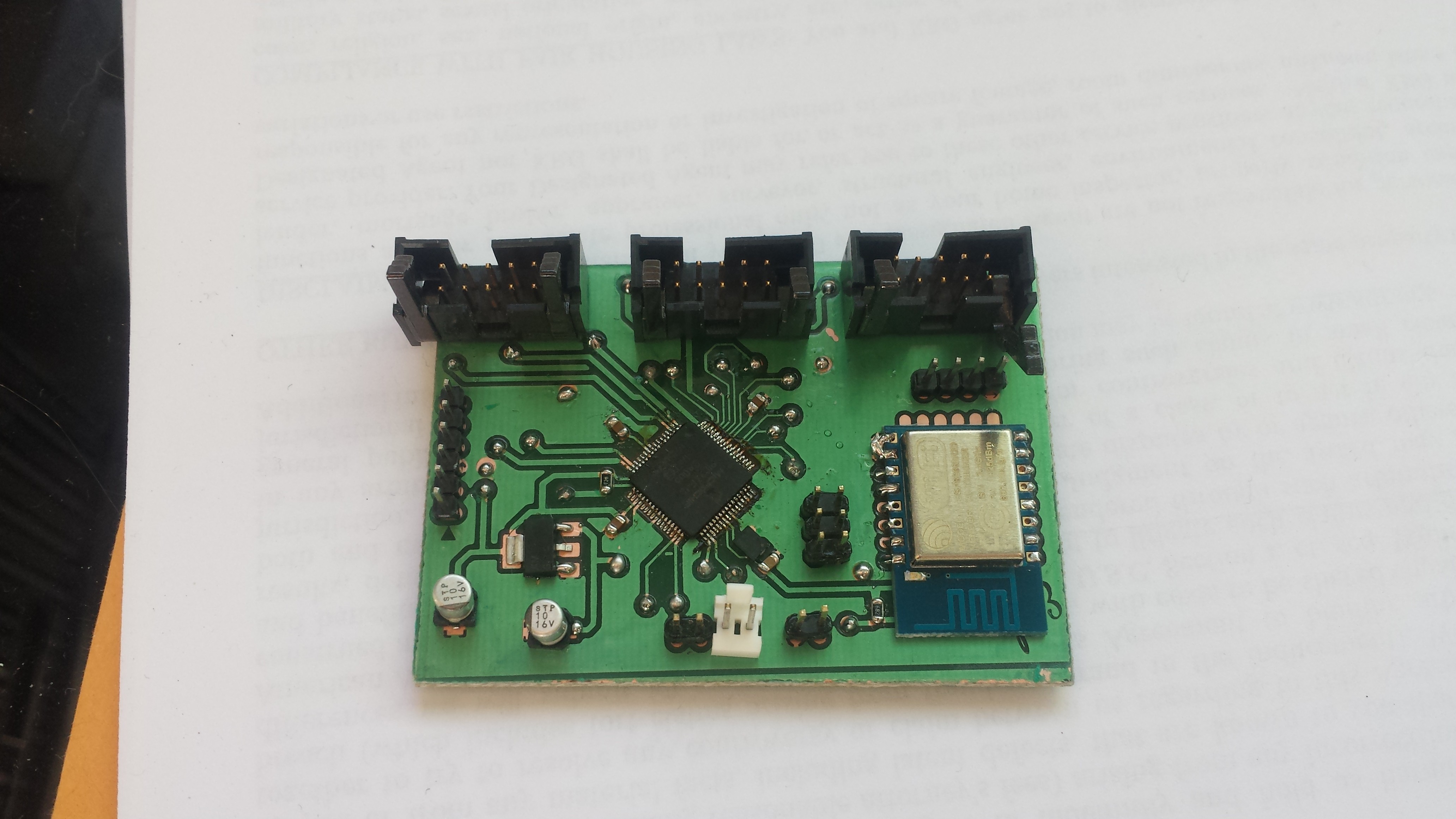
and this board -
![]()
-
Letter Bits + Codes
11/08/2015 at 21:09 • 0 commentsI`ve downloaded a number of letter codes designed for LED matrix displays and started playing with each to see which one look best. ended up going with an array of 250 standard 6x8 characters. each character is an array of 8 integers - each integer represent a row of pixels and each bit represent a pixel.
Example - "A" : (112,136,136,136,248,136,136,0)
112 = -ooo---
136 = o---o---
136 = o---o---
136 = o---o---
248 = ooooo---
136 = o---o---
136 = o---o---
0 = --------
Full list of characters supported by display -
![]()
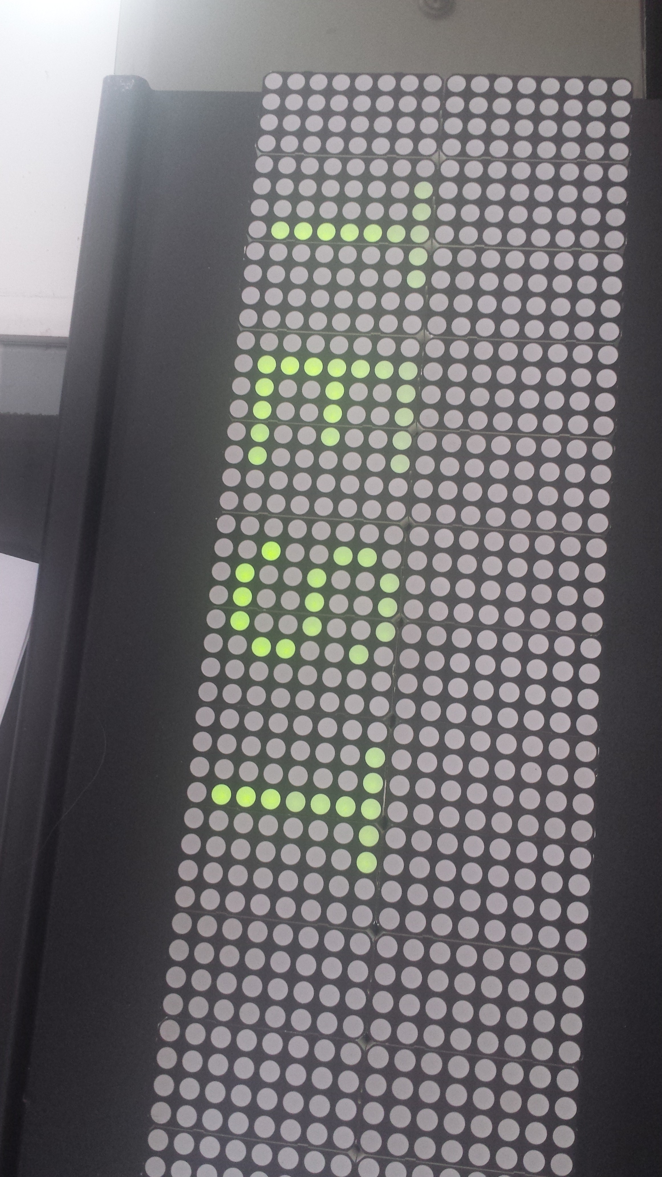
After wiring up the letter codes, i managed to get my first TEST going :
![]()
-
Test Connections / Initial Code
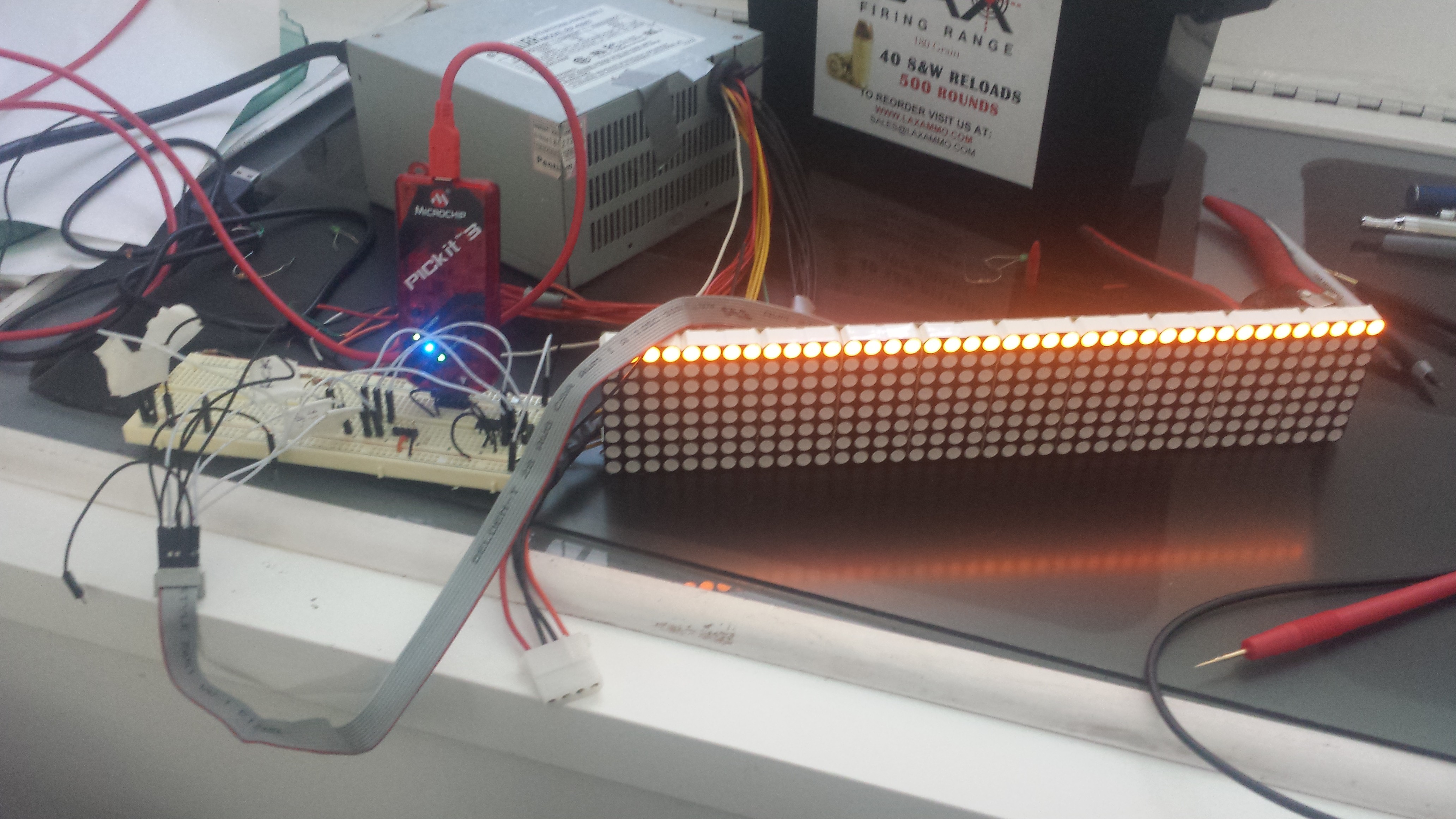
11/08/2015 at 20:56 • 0 commentsI took a part one of the display boards (10x[4x8] blocks) and wired it up to PIC24FJ64GB002, then created a simple loop that`ll call the shift register on the block and attempt to display a message on it
The idea was to check my connection and pin-probing
the pseudo code I wrote was something like -
while(true){
// Set Row IDs for current row (row 4):
ROW_1 = 0
ROW_2 = 1
ROW_3 = 1
// Shift for each pixel in the row -
for each pixel in row {
SRCK = 0
Green Bit = 1 // Turn pixel ON
SRCK = 1
// Shift next row
}
RCK = 0
RCK = 1
}
This code generated to following -
And -![]()
![]()
-
Display Units
11/08/2015 at 20:38 • 0 commentsEach display has an array of 16x3 and 20x2 boards, each board contains an array of 10 x (4x8) RGY LED blocks
Boards are serially linked to each other in each row
Each row is connected to the board using a 10 bit ribbon
The ribbons are connected from the main board to a OCT buffer (HCT244) and a shift register
After some poking around, i found the following lines -
RCK (Pin 10) Green Bit Row ID (3) SRCK Row ID (1) Row ID (2) SRCK 5v+ Red Bit GND (Pin 1) RCK - Shift Register RCK
Green Bit - Shift HIGH to light up Green pixel
Row ID (1-3) - a 3 bit number for the following rows - (ID 1,2,3)
Row 1 - 000 Row 2 - 001 Row 3 - 010 Row 4 - 011 Row 5 - 100 Row 6 - 101 Row 7 - 110 Row 8 - 111 SRCK - Shift Register SRCK
5v+ - positivie
Red Bit - Shift HIGH to light up Red pixel
-
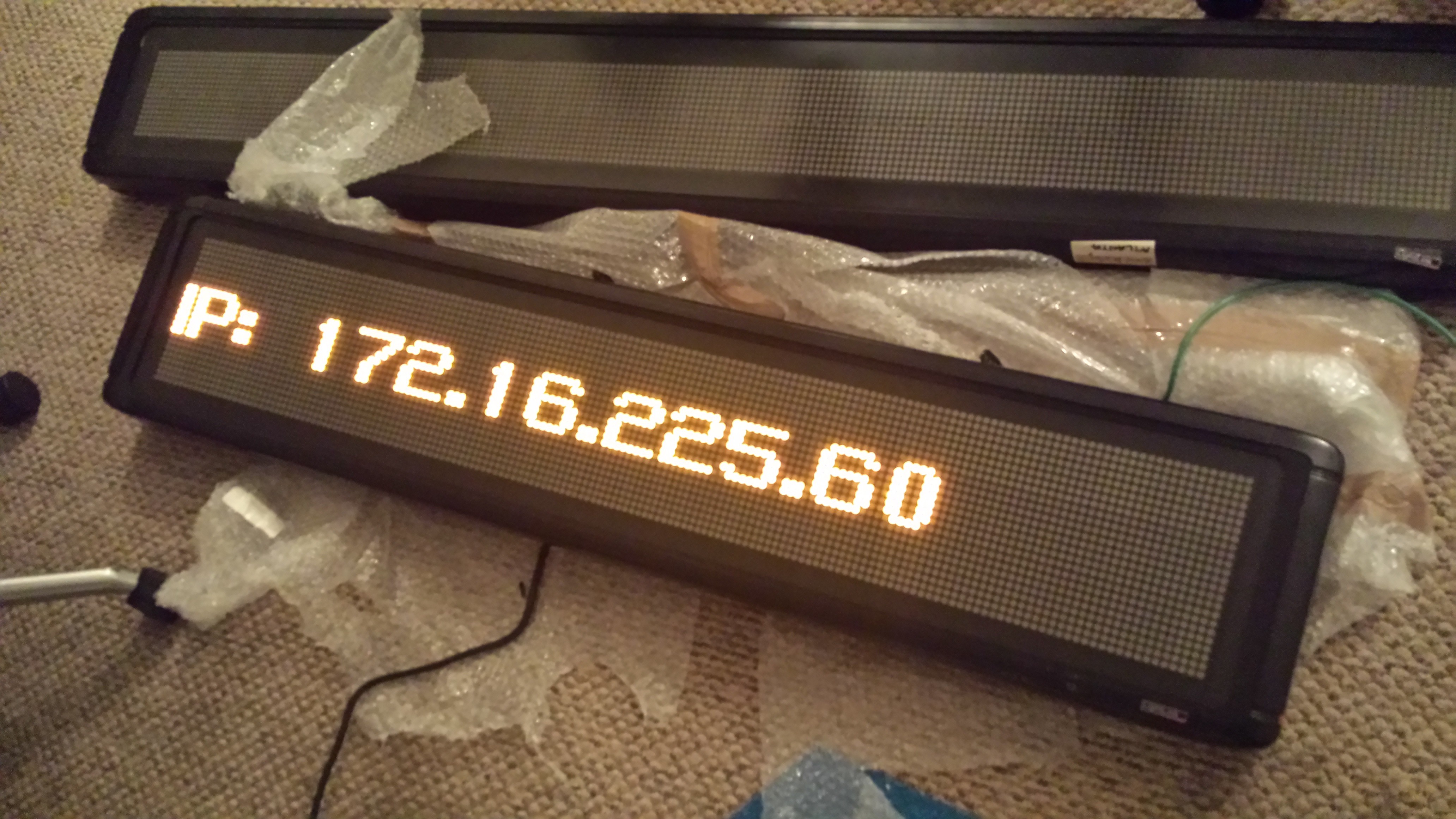
Initial Recon
11/08/2015 at 20:15 • 0 comments![Original board]()
- Both displays use the same old (circa' 96) control boards made by LightLink / Inova
- Controlling board has a 10baseT interface (multiple ports)
- When light up + connected to a router, both signs display an IP address information
- Port scanning returned nothing.
![Device info]()
after a quick google search i found that these screens connect via UDP - but no luck finding the packet format / protocol
I`ve decided to rebuild the controller board using a simple PIC + ESP8266 combo and write my own protocol for the display
![]()
LED Matrix Controller
Replacing an old Lightlink/Inova FPGA Scrolling LED board controller with PIC24F + ESP8266