jeromekelty
-
Build log 4- electronics
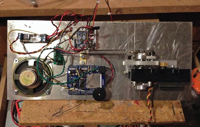
04/19/2014 at 06:34 • 0 commentsThe electronics for this were pretty straightforward. The biggest issue with servo systems is to make sure the servos are powered from their own regulator- this will help isolate any electrical noise generated by the servos that would otherwise cause glitches in the servo movements.
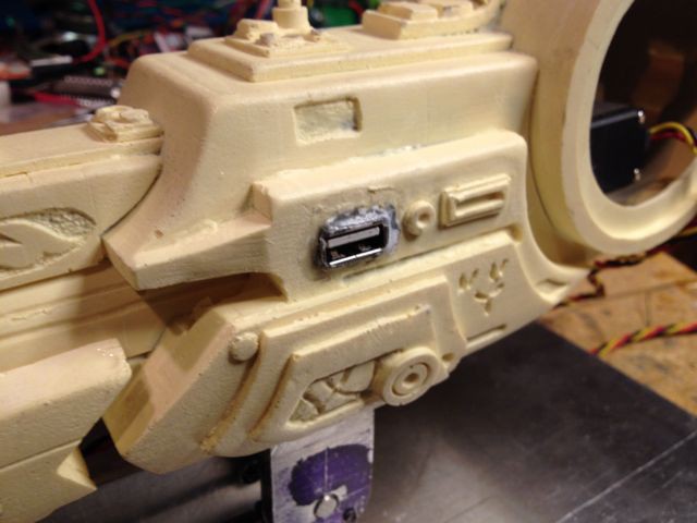
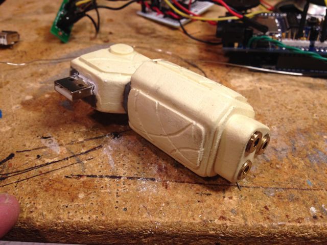
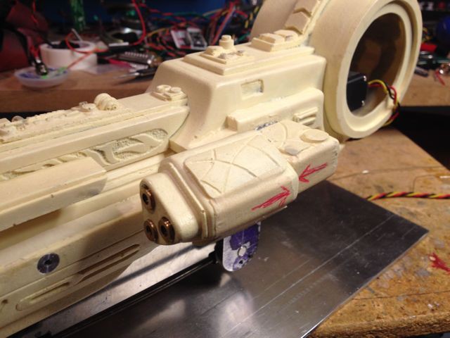
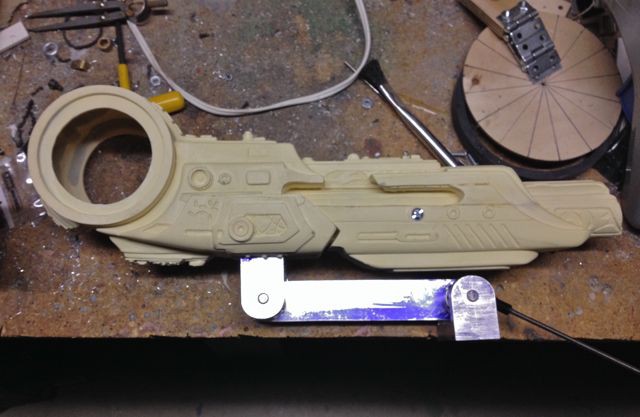
Holes were drilled in the Aluminum base plate for the speaker and for running wires up the cannon arm. I decided to attach the laser sight pod to the cannon body using a USB port so it would be easy to detach it for painting and shipping. The female port was added to the cannon body using some ProPoxy20 epoxy putty and the same was done with the male end in the laser sight.
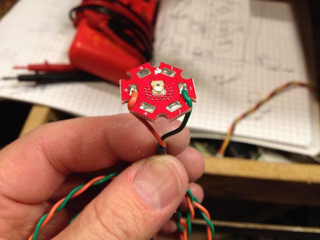
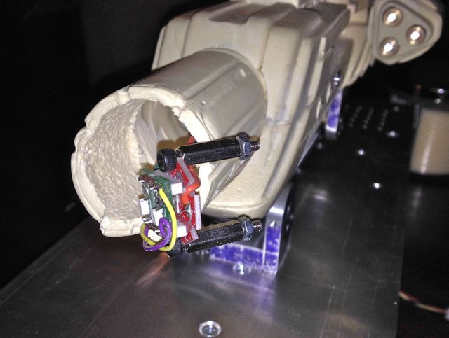
The Luxeon LED was added to the inside of the cannon barrel using two standoffs and two SMT LEDs were attached to the front of the Luxeon LED board. The wires for the LEDs and laser sight were then run along the inside of the cannon and they exited the canon just behind the upper arm end and then ran down the cannon arm. All of the electronics boards were then attached to the base plate using standoffs and a lower base plate was attached to the cannon base plate with three threaded Aluminum rods.
![]()
![]()
![]()
![]()
![]()
![]()
-
Build log 3- arm servo
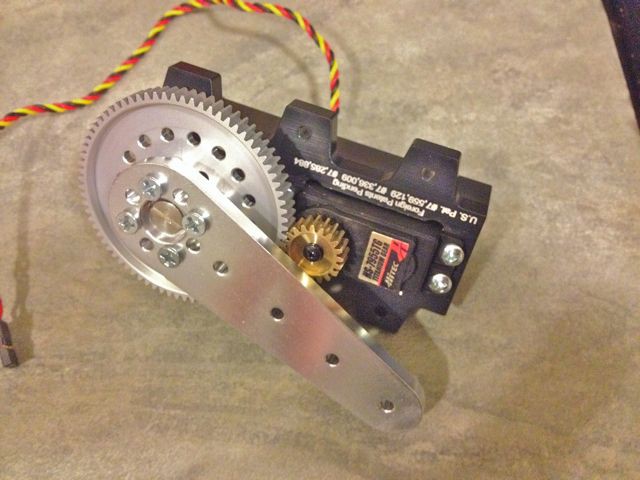
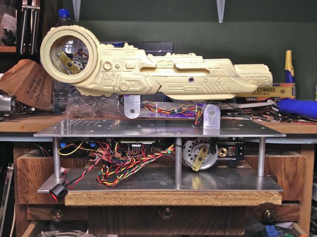
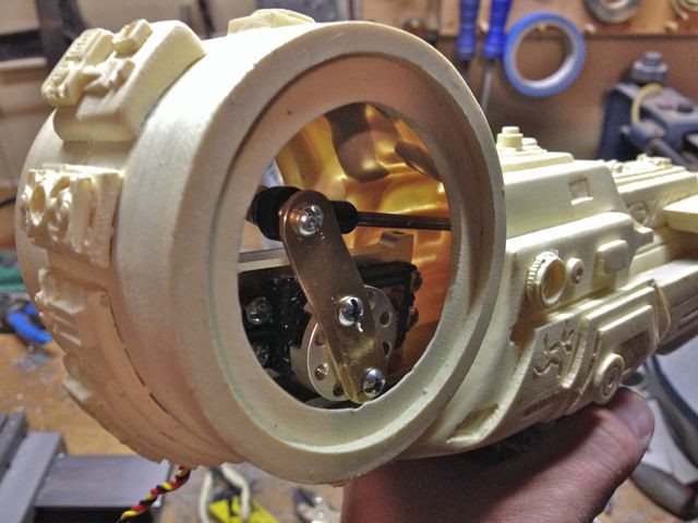
04/19/2014 at 05:58 • 0 commentsTo raise the arm I needed a very powerful servo so I used a geared servo drive to boost the servo's output torque. These servo drives use an external potentiometer attached to the output shaft drive gear for positional control. A thick Aluminum arm was modified and attached to the output shaft. The lower cannon arm end was then bolted to a large 1/8" thick Aluminum base plate and the geared servo drive was mounted underneath the base plate. The swivel link from the cannon arm was then attached to the servo output arm.
Later on during testing I found that while the cannon raised beautifully the weight of the cannon still caused it to drop too fast and it had a jerky motion to it that I didn't like. To solve this I added a brass arm to the servo output shaft and attached an extension spring to it to act as a counterbalance in order to reduce the load on the servo and smooth the lowering motion of the cannon.
![]()
![]()
![]()
![]()
-
Build log 2- recoil mechanism
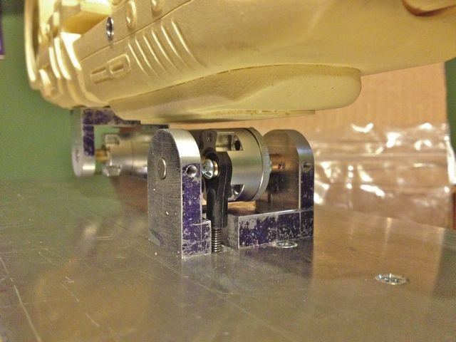
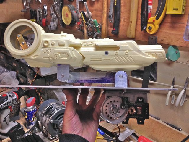
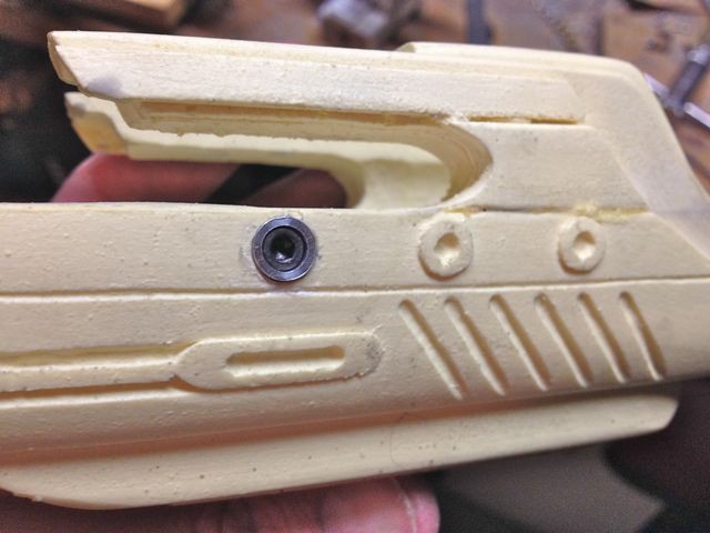
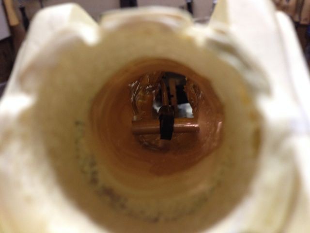
04/19/2014 at 05:10 • 0 commentsThe cannon has a sliding housing for the front of the barrel and there are slots cut in the barrel for a through bolt, which holds a 6-32 swivel link. Two machined Aluminum supports for the bolt were added to match the external appearance of the cannon and locate the bolt as it slides through the slot. A threaded rod connects the through bolt swivel link to a second link that is attached to the recoil servo arm. The servo has a high strength Aluminum hub and a brass arm is bolted to this. As the servo arm rotates the sliding housing moves forward and back.
![]()
![]()
![]()
![]()
![]()
![]()
![]()
-
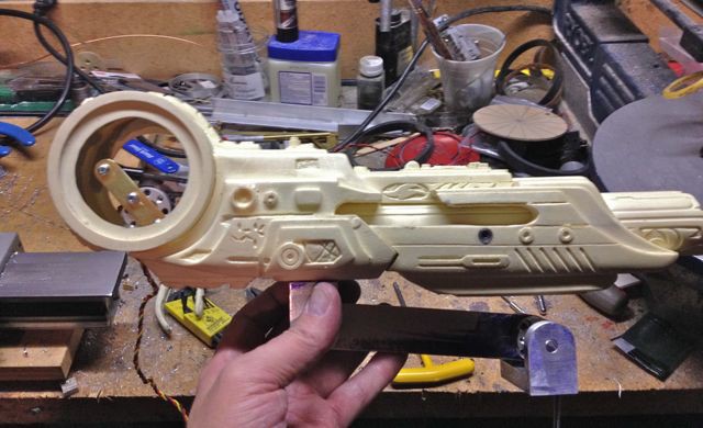
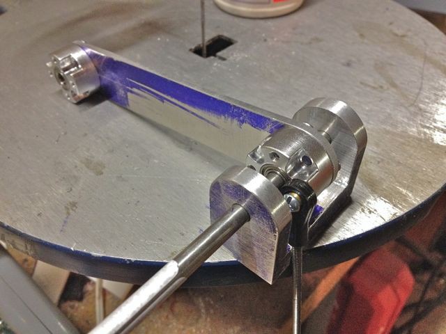
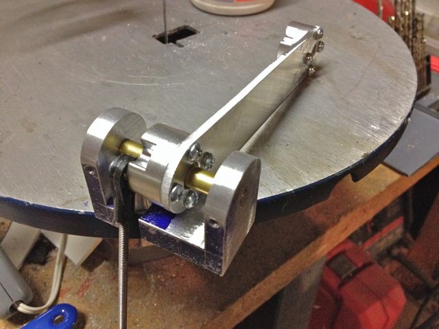
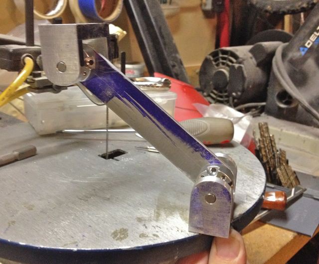
Build log 1- arm construction
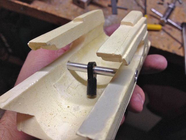
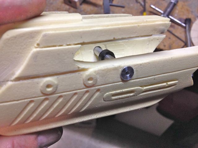
04/19/2014 at 03:56 • 0 commentsThe arm is made from 1/8" thick Aluminum sheet and a bearing hub is fitted to each end of the arm. The arm end mounts are machined from 1" thick Aluminum plate and 1/4" diameter stainless steel rods are fitted as pivots for the arm bearings. The rods are held in place by 4-40 set screws in the arm end mounts. Spacers made from brass tubing keep the arm centered in the end mount. A 6-32 swivel link was attached to the lower bearing hub- this is what the geared servo pulls on in order to raise the arm. A notch was milled in the lower arm end mount to allow clearance for the pull rod and swivel link.
There is a threaded rod on one side of the arm that is attached to each end mount with swivel links- this forms a parallel linkage that keeps the upper arm end mount level as the arm raises. The cannon has an Aluminum plate fitted to the inside bottom and the upper arm end mount is attached to the bottom of the cannon with two 6-32 bolts.
![]()
![]()
![]()
![]()
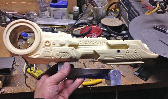
Animatronic AVP Predator cannon
An animatronic display piece that is activated by an ultrasonic sensor