 Jan Godde
-
1Step 1
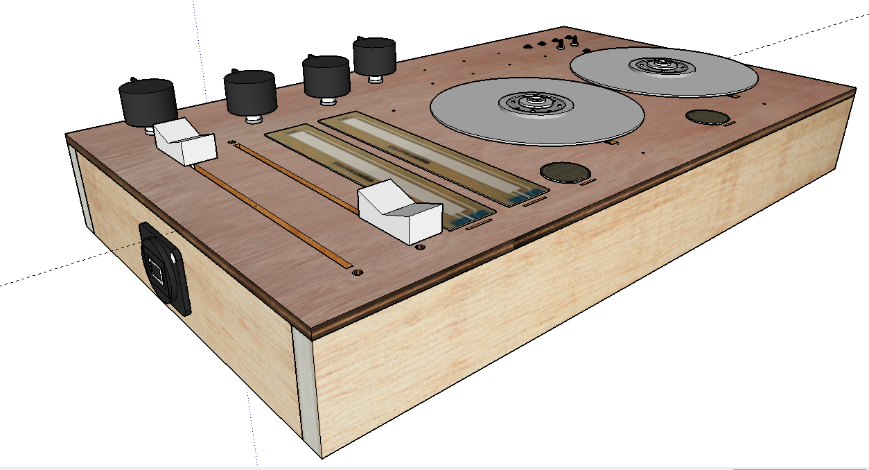
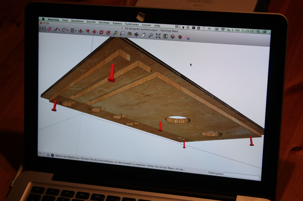
I was designing this box with SketchUp. I knew the dimensions, and what sensors I'd like to use, but hardly more. Here is how i ended up with the 3D model:
![]()
-
2Step 2
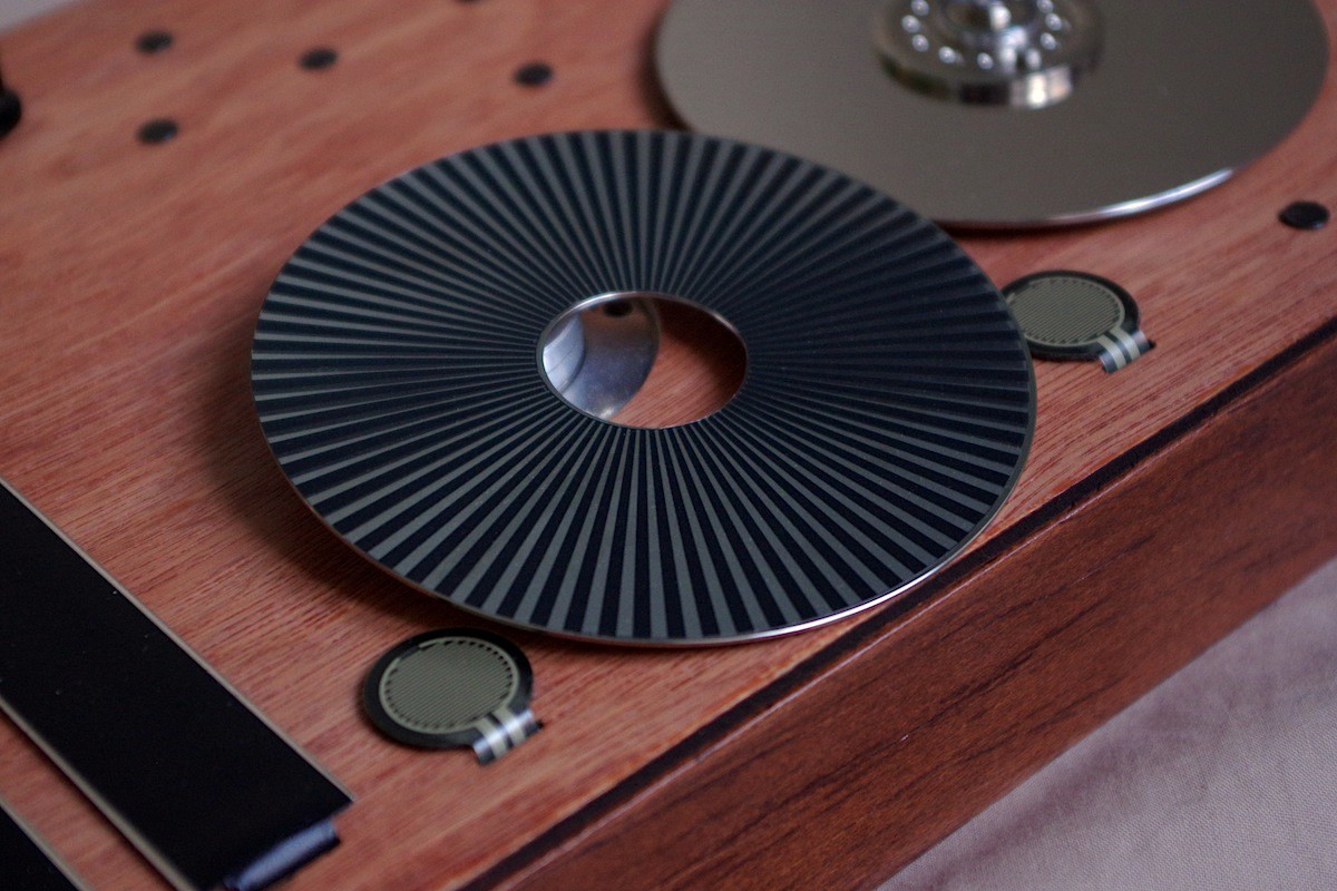
For sensing the movement of the rotary disks (which i hacked out of two old hard drives i had lying around) i was thinking about different approaches. If you look around in the web, there are a couple of DIY maker projects hacking hard disk drives. I could have hacked any optical mice and have the camera look at the disk movement. I could have measured the voltage on the hard disk connectors that appears while spinning the hard drive (amplifying necessary, resolution questionable). I think by measuring the voltages on the hard disk contact pins you can still achieve pretty good results.There's a number of other hard disk jog wheel projects out there. I decided to use reflective optoelectronics. Using Quadrature Encoding, i could go with a good resolution (with 77 black bars, i get 4x77 = 308 ticks per revolution). This is the disk with the pattern for the IR sensor:
![]()
The IR sensors i used are named "ITR9904". You can use other sensors as well. There are many IR sensors like this, in one housing, with both one IR LED and one phototransistor. With this design, they have to make use of IR reflection, not transmission.
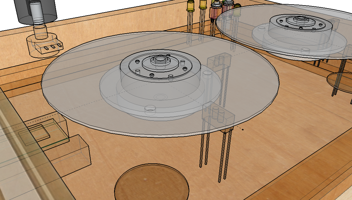
With the IR sensors, i can measure a high voltage if IR light is reflected, and a low voltage if not. Very important was the exact position of the two sensors. They have to be in an angle of 90 degrees in order to make the Quadrature Encoding possible with this approach. This works if we have an odd number of black (absorbing) stripes on the disk. Here you can see how i placed the sensors below the disk (90°) in the 3D model:
![]()
-
3Step 3
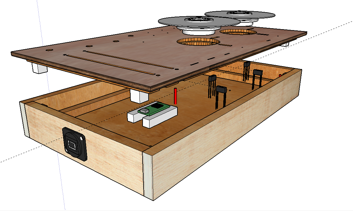
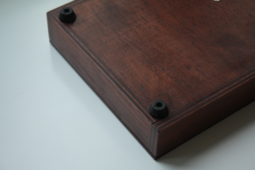
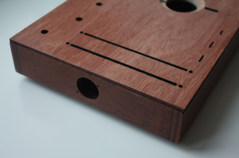
The top panel was built out of two laser cut wood layers that i glued together. The red bars indicate the positions at which i added extra wood blocks that i could put screws into for connceting the top panel to the rest of the box. The screws are hidden by case feet.
![]()
![]()
![]()
-
4Step 4
I applied wood stain to the lower part of the box (not the top panel). As a protective finish, i used wood varnish.
![]()
-
5Step 5
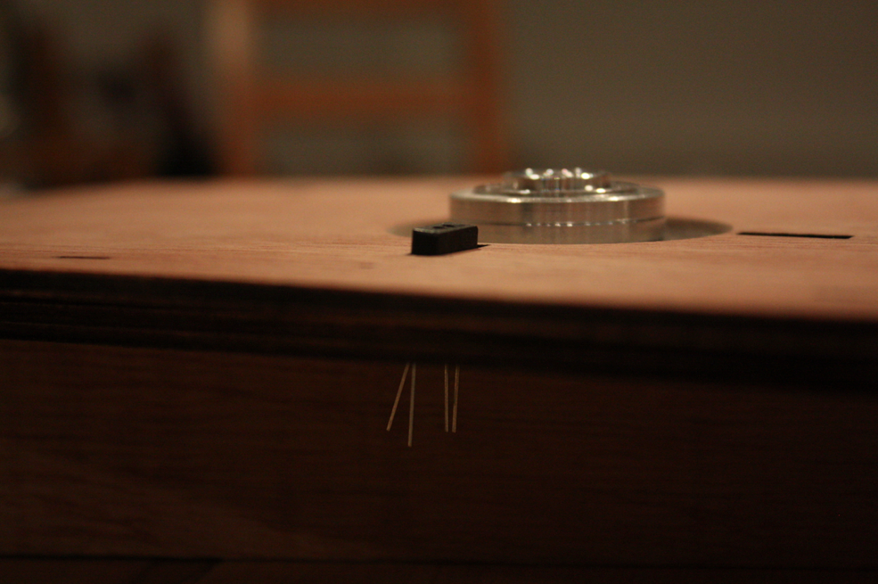
I had to adjust the height of the IR sensors really carefully. In the datasheet i could find a distance value (something like 3mm) where the sensors are said to work best.
![]()
-
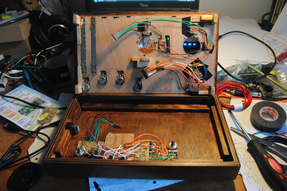
6Step 6
After building the box, of course, I soldered all the parts to the Teensy.
![]()
To connect the IR sensors to the digital pins of the Teensy, i used two LM358 op-amps as comparators with hysteresis, so that i only get voltages that are either HIGH or LOW (+Vcc/-Vcc) and that there are no glitches on the transitions from LOW to HIGH, or vice versa. Maybe i could have implemented the hysteresis in software, but as i use interrupts on the Teensy, i wanted to go safe.
-
7Step 7
The last part was doing all the software. I am using the Arduino IDE with Teensyduino, the <Bounce.h> library for the switches and the <Encoder.h> library for the rotary disks Quadrature Encoding. I am collecting the sensor data, writing it to the serial port. In Processing, i receive the data, and use it to control the visual elements. Most important, from here, I also send the data to Pure Data with the pdp5 library. The data is being mapped to musical parameters. You can find snippets of code in the project log entries.
Wooden sensor box w/ 2 rotary disks
A homebuilt wooden sensor box i made, mainly for controlling PureData.
Discussions
Become a Hackaday.io Member
Create an account to leave a comment. Already have an account? Log In.