Jan Godde
-
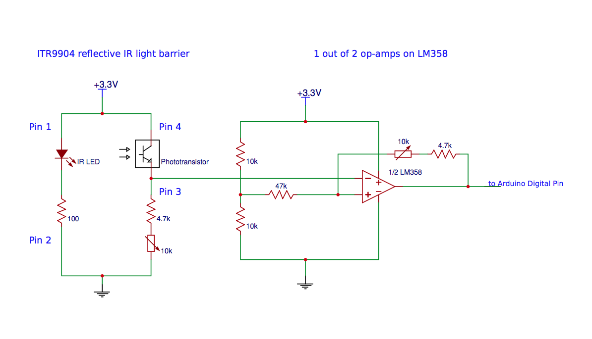
Schematics and wiring
11/10/2015 at 12:00 • 1 commentThis is how one IR sensor and one op-amp are connected to the Teensy. I use some variable resistors for finetuning the thresholds. Keep in mind that operating a LM358 op-amp with only 3.3V will not give you the full output range. The output range will be missing 2V, so it will be only 1.3V (HIGH ~2.2V, LOW ~0.9V).
Two IR sensors are needed to sense direction and speed of one hard disk platter. When using only one, there is no chance for calculating the direction. When using two sensors with a 90° angle offset, you can make use of the Quadrature Encoding technique.
![]()
To connect the ribbon and pressure sensors is easy. See, for example:
Connect a pressure (FSR) sensor
SoftPot ribbon sensor product page
On the SoftPot product page, it's said not to connect Ground and Power directly. So make sure to put a 10kOhm resistor in series to connect the ground and the power pin. The center pin can be read directly.
The faders and potentiometers are connected to the Teensy like this.
For the switches, i used the <Bounce.h> library. On this page, you can find detailled information on using the switches. It's nice that you only need one digital pin and a ground connection for each switch.
The LEDs are connected with a resistor in series to make sure that there is not too much current flowing. The longer leg is connected to a digital pin, the shorter with a resistor to ground. As i used really bright white LEDs, i chose a bigger resistor than you would normally do to limit the light intensity.
The touch buttons are connected to the Teensy's touch pins directly.
-
The touch sensing and touchRead()
11/09/2015 at 19:14 • 0 commentsFor reading the touch sensors, i simply use the "touchRead()" operator that you get with Teensyduino (Teensy 3.0 and higher). To be honest, i don't know precisely what the Teensy is doing here. It's some advanced capacitive sensing technology that is implemented with the new Teensy boards. I read something about a reference capacitor equalling out changing conditions. It's said to be faster and giving more reproducible results than when using the old technique with 2 pins, a resistor and the CapSense library (Arduino CapSense article).
Now i may have made a mistake in the design as i was just reading some articles about capacitive touch sensing and it seems that you have improved readings using a grounding plate surrounding the sensor. It seems that the better touch sensing is with an electrical field between two capacitor plates that you change while bringing your finger closer to this system. This would mean there is a metal sensor object that is connected to the touch pins of the Teensy and a grounding plate (connected to ground), surrounding this object. In my design, i just soldered cables to the nails and connect the cables to Teensy's touch pins, making use of touchRead().
This is working quite good, but I have to tell you, that the pin readings change drastically when i touch, for example, the housing of my laptop computer. I will try to make some changes and improve my design.
See The art of capacitive touch sensing for more information on the topic, though this may not be the same technology as the one that touchRead() is working with in the new Teensy boards. Also have a look at the PRJC (Teensy) forum. There are some posts on this topic.
-
Processing sketch
11/09/2015 at 19:05 • 0 commentsThis is the Processing code i used in the second demo video demonstrating the rotary disks.
It is receiving the Teensy data from the serial port (for communication syntax, see Arduino code in the other project log entry).
The wheel resolution (see LEDMode in Arduino code) is being controlled here.
All the values are being scaled.
// ***** wheelController Software ***** // ******** Jan Godde, 2015 ******** // PROCESSING RECEIVE SKETCH FOR arduinoSendWheelsMore SKETCH // USING PHASE VOCODER IN PD IN soundWheel.pd SKETCH import processing.serial.*; import org.puredata.processing.PureData; PureData pd; // don't forget: expr operator seems not to be working with pdp5! final int REVOL = 308; // resolution optimized: 4 x (77 black bars) Serial myPort; String thisString = "0"; int[] splitString = {-1, -1, -1, -1, -1, -1, -1, -1, -1, -1}; int LEDMode; int wheel2Mode; float pos1, pos2; float ribbon1, ribbon2, fader1, fader2, fsr1, fsr2; float knob1, knob2, knob3, knob4; float lefttouch, righttouch, mono, wheeltouch1, wheeltouch2; float[] inputValue = {0, 0, 0, 0, 0, 0, 0, 0, 0, 0}; //fader, pressure, knobs, 2 wheels float[] touch = {0, 0, 0, 0, 0}; //2 touch ducking - 1 touch mono (middle) - 2 wheel touch float[] ribbon = {0, 0}; void setup() { pd = new PureData(this, 44100, 0, 2); pd.openPatch("wheelSound.pd"); pd.start(); size(1200,700); background(0); noStroke(); smooth(); LEDMode = 0; wheel2Mode = 0; String portName = Serial.list()[4]; // N° 4 myPort = new Serial(this, portName, 57600); //myPort.bufferUntil('\n'); myPort.clear(); } void draw() { myPort.clear(); lefttouch = constrain( map(touch[0], 1000, 5700, 0, 1000), 0, 1000 ); righttouch = constrain( map(touch[1], 1050, 5700, 0, 1000), 0, 1000 ); mono = constrain( map(touch[2], 1000, 5700, 0, 1000), 0, 1000 ); wheeltouch1 = constrain( map(touch[3], 1500, 6500, 0, 1000), 0, 1000 ); wheeltouch2 = constrain( map(touch[4], 1500, 6500, 0, 1000), 0, 1000 ); fader1 = constrain( map(inputValue[0], 0, 1023, 0, 1000), 0, 1000 ); //fader1 fader2= constrain( map(inputValue[1], 0, 1023, 0, 1000), 0, 1000 ); //fader2 fsr1 = constrain( map(inputValue[2], 0, 700, 0, 1000), 0, 1000 ); //fsr1 fsr2 = constrain( map(inputValue[3], 200, 700, 0, 1000), 0, 1000 );//fsr2 knob1 = constrain( map(inputValue[4], 0, 1023, 0, 1000), 0, 1000 ); //knob1 knob2 = constrain( map(inputValue[5], 0, 1023, 0, 1000), 0, 1000 ); //knob2 knob3 = constrain( map(inputValue[6], 0, 1023, 0, 1000), 0, 1000 ); //knob3 knob4 = constrain( map(inputValue[7], 0, 1023, 0, 1000), 0, 1000 ); //knob4 ribbon1 = constrain( map(ribbon[0], 450, 750, 0, 1000), 0, 1000 ); ribbon2 = constrain( map(ribbon[1], 450, 750, 0, 1000), 0, 1000 ); drawWheels(inputValue[8], inputValue[9], wheeltouch1, wheeltouch2); pos1 = constrain( map(inputValue[8], 0, ((LEDMode+1)*REVOL), 0, 1000), 0, 1000 ); pos2 = constrain( map(inputValue[9], 0, ((LEDMode+1)*REVOL), 0, 1000), 0, 1000 ); // send all values from 0...1000 pd.sendFloat("vol1", (float)fader1); //fader1 pd.sendFloat("vol2", (float)fader2); //fader2 pd.sendFloat("pvrev1", (float)knob2); //knob2 pd.sendFloat("pvrev2", (float)knob3); //knob3 pd.sendFloat("drywet1", (float)knob1); //knob1 pd.sendFloat("drywet2", (float)knob4); //knob4 pd.sendFloat("pos1", (float)pos1); // wheel 1 position pd.sendFloat("pos2", (float)pos2); // wheel 2 position pd.sendFloat("transpose1", (float)fsr1); //fsr1 pd.sendFloat("transpose2", (float)fsr2); //fsr2 pd.sendFloat("touch7", (float)lefttouch); pd.sendFloat("touch9", (float)righttouch); pd.sendFloat("touch8", (float)mono); // "mono" channel cross-talk pd.sendFloat("wheeltouch1", (float)wheeltouch1); // wheel touch 1 & 2 pd.sendFloat("wheeltouch2", (float)wheeltouch2); pd.sendFloat("wheel2mode", (float)wheel2Mode); // scratch mode on/off on wheel 2 pd.sendFloat("ribbon1", (float)ribbon1); pd.sendFloat("ribbon2", (float)ribbon2); } void drawWheels(float pos1, float pos2, float touch1, float touch2) { background(0); noFill(); //fill(255); strokeWeight(4); stroke(255); ellipse(310, 350, 500, 500); ellipse(890, 350, 500, 500); strokeWeight(20); pushMatrix(); translate(310,350); rotate(radians((pos1/(REVOL*wheelResolution()))*360)); stroke(55+((touch1/1000)*200)); line(0,0,0,-220); popMatrix(); pushMatrix(); translate(890,350); rotate(radians((pos2/(REVOL*wheelResolution()))*360)); stroke(55+((touch2/1000)*200)); line(0,0,0,-220); popMatrix(); } void serialEvent (Serial myPort){ thisString = myPort.readStringUntil('\n'); if (thisString != null){ thisString = trim(thisString); splitString = int(split(thisString, ' ')); if (splitString.length == 19){ inputValue[0] = int(splitString[0]); inputValue[1] = int(splitString[1]); inputValue[2] = int(splitString[2]); inputValue[3] = int(splitString[3]); inputValue[4] = int(splitString[4]); inputValue[5] = int(splitString[5]); inputValue[6] = int(splitString[6]); inputValue[7] = int(splitString[7]); touch[0] = int(splitString[8]); touch[1] = int(splitString[9]); touch[2] = int(splitString[10]); touch[3] = int(splitString[11]); touch[4] = int(splitString[12]); inputValue[8] = int(splitString[13]); // wheel left position inputValue[9] = int(splitString[14]); // wheel right position LEDMode = int(splitString[15]); wheel2Mode = int(splitString[16]); ribbon[0] = int(splitString[17]); ribbon[1] = int(splitString[18]); } } } float wheelResolution(){ switch(LEDMode){ case 0: return 1.0; case 1: return 2.0; case 2: return 3.0; case 3: return 4.0; case 4: return 5.0; } return 1.0; } -
Arduino (Teensyduino) Code
11/09/2015 at 19:01 • 0 commentsThis is the code that i am using in the second demo video, demonstrating the rotary disks. This code may be still a mess, and there may be some stupid solutions, but so far it works.
I am not reading in all the touch sensors as for this example i only need a few.
For reading the touch sensors, i simply use the "touchRead()" operator that is working with Teensyduino (Teensy 3.0 and higher). This is working quite good, but I have to tell you, that the pin readings change drastically when i touch, for example, the housing of my laptop computer. I will try to make some changes and improve my design. I posted another project log entry on this topic.
The two switches change a mode that is represented by the first 4 LEDs. The higher the mode (LEDMode: 0, 1, 2, 3, 4), the slower the values change when disks are spun. So it decreases the sensitivity of the wheels, making the wheel movements more precise.
When both switches are pressed, a second mode (LED5Mode) is changed (0, 1), displayed by LED number 5.
If you wonder about all the Serial.print() operators at the end of the sketch, this is how the data is being sent to Processing (see Processing code).
// ***** wheelController Software *****
//  ******** Jan Godde, 2015 ********
// ARDUINO SETTINGS FOR processingReceiveWheels SKETCH
//     USING PHASE VOCODER IN PD IN soundWheel.pd SKETCH

#include <Encoder.h>
#include <Bounce.h>
#define ENCODER_OPTIMIZE_INTERRUPTS
#define REVOL 308 // resolution optimized: 4 x (77 black bars)

int LEDMode = 0;
int LED5Mode = 0;
int switch1last, switch2last;
int LEDState[5][5] = { {LOW, LOW, LOW, LOW, LOW}, {HIGH, LOW, LOW, LOW, LOW},
                       {LOW, HIGH, LOW, LOW, LOW},
                       {LOW, LOW, HIGH, LOW, LOW}, {LOW, LOW, LOW, HIGH, LOW} };

Encoder knobLeft(9, 10);
Encoder knobRight(11, 12);
Bounce switch1 = Bounce(2, 5); // (pin number, 5 ms debounce time)
Bounce switch2 = Bounce(3, 5); // switch 1: D2, switch2: D3
// int sensorPin[20] = { A7, A6, A14, A20, A10, A11, A15, A16, //fader - fsr - knobs
//                     0, 1, 15, 16, 17, 18, 19, 22, 23, 25, 32, 33 }; //touchPins
int sensorPin[13] = { A7, A6, A14, A20, A10, A11, A15, A16, //fader - fsr - knobs
             0, 33, 32, 1, 25}; // 3 touchPins & 2 wheelTouch
int ribbonPin[2] = {A0, A19};
int ribbonValue[2] = {0, 0};
int ribbonTouched[2] = {0, 0};
int LEDPin[5] = {4, 5, 6, 7, 8};
int outputValue[15]; //with wheel encoder at last two positions

int positionLeft  = 0;
int positionRight = 0;

//int newLeft, newRight;

void setup() {
    Serial.begin(57600);
  pinMode(A14, INPUT_PULLUP);//fsr1
  pinMode(A20, INPUT_PULLUP);//fsr2
  pinMode(A0, INPUT_PULLUP);//ribbon1
  pinMode(A19, INPUT_PULLUP);//ribbon2
  pinMode(2, INPUT_PULLUP);  //switch1
  pinMode(3, INPUT_PULLUP);  //switch2
  pinMode(4, OUTPUT);
  pinMode(5, OUTPUT);
  pinMode(6, OUTPUT);
  pinMode(7, OUTPUT);
  pinMode(8, OUTPUT);
}

void loop() {
  LEDStateChange();

  if (switch1.update()){
    if(switch1.fallingEdge()) {
      switch1last = 1;
      LEDMode = mod((LEDMode-1),5);
      if (switch2last == 1){
        wheel2StateChange();
      }
    }
    if(switch1.risingEdge()) {
      switch1last = 0;
    }
  }

  if (switch2.update()){
    if(switch2.fallingEdge()) {
      switch2last = 1;
      LEDMode = mod((LEDMode+1),5);
      if (switch1last == 1){
        wheel2StateChange();
      }
    }
    if(switch2.risingEdge()) {
      switch2last = 0;
    }
  }

  //Serial.print(switch1last);
  //Serial.print(" ");
  //Serial.println(switch2last);

  // COLLECT SENSOR DATA:
  for(int i = 0; i < 8; i++){
    outputValue[i] = analogRead(sensorPin[i]);
  }
  for(int i = 8; i < 13; i++){
    outputValue[i] = touchRead(sensorPin[i]);
  }
  ribbonRead();

  int newLeft, newRight;
  newLeft = knobLeft.read();
  newRight = knobRight.read();
  //newLeft = newLeft + 1;
  //newRight = newRight + 2;
  if (newLeft != positionLeft || newRight != positionRight) {
    newLeft = mod(newLeft, (LEDMode+1)*REVOL);
    newRight = mod(newRight, (LEDMode+1)*REVOL);
    //knobLeft.write(0);
    //knobRight.write(0);
    positionLeft = newLeft;
    positionRight = newRight;
  }

  //**************************//

  for(int i = 0; i < 13; i++){
    Serial.print(outputValue[i]); // fader, fsr, knobs, some touchpins
    Serial.print(" ");
  }
  Serial.print(newLeft); // wheel position left
    Serial.print(" ");
  Serial.print(newRight); // wheel position right
    Serial.print(" ");
  Serial.print(LEDMode); // LED Mode (0 - 4)
    Serial.print(" ");
  Serial.print(LED5Mode); // fifth LED Mode (0, 1)
    Serial.print(" ");
  Serial.print(ribbonValue[0]); // ribbon1
    Serial.print(" ");
  Serial.print(ribbonValue[1]); // ribbon2

  Serial.println(" ");
    delay(5);

  Serial.flush();
  //**************************//

}

void ribbonRead() {
  for (int i = 0; i < 2; i++) {
    int readSensor = analogRead(ribbonPin[i]);
    if (readSensor >= 950) {
      ribbonTouched[i] = 0;
    }
    else if (readSensor < 950) {
      ribbonTouched[i] = 1;
      ribbonValue[i] = readSensor;
    }
  }
}

void LEDStateChange(){
    digitalWrite(4, LEDState[LEDMode][0]);
    digitalWrite(5, LEDState[LEDMode][1]);
    digitalWrite(6, LEDState[LEDMode][2]);
    digitalWrite(7, LEDState[LEDMode][3]);
  }

void wheel2StateChange(){
  if (LED5Mode == 0){
    digitalWrite(8, HIGH);
    LED5Mode = 1;
  }
  else if (LED5Mode == 1){
    digitalWrite(8, LOW);
    LED5Mode = 0;
  }
}

int mod(int n, int x){ // MODULO function
  return ((n%x)+x)%x;
}
Wooden sensor box w/ 2 rotary disks
A homebuilt wooden sensor box i made, mainly for controlling PureData.