 Joseph Lavoie
-
1Step 1
Construction of the Water cooling Jacket::
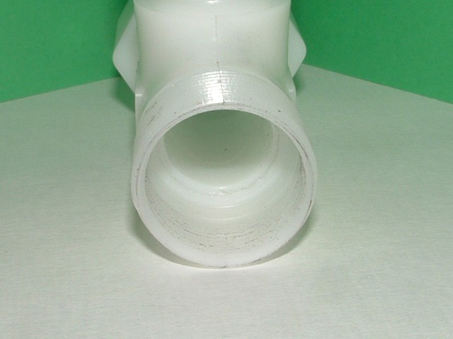
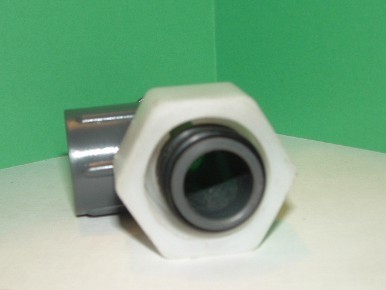
The Nylon snap lock fittings were machined to allow the 1 inch, Outer Glass tube to fit easly to a depth of 1 inch.
The same edge of the snap lock fitting was bevelled to accept the Rubber O ring.
![]()
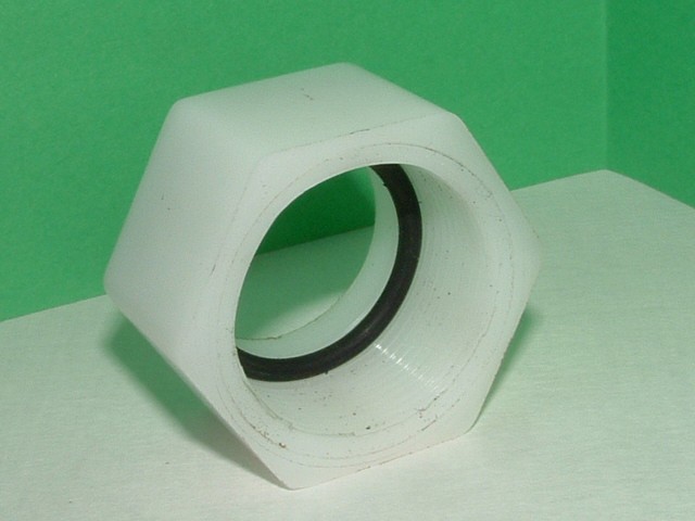
Next the Compession Nut was shortened by .25 of an inch and machined to fit over the 1 inchGlass tube.
![]()
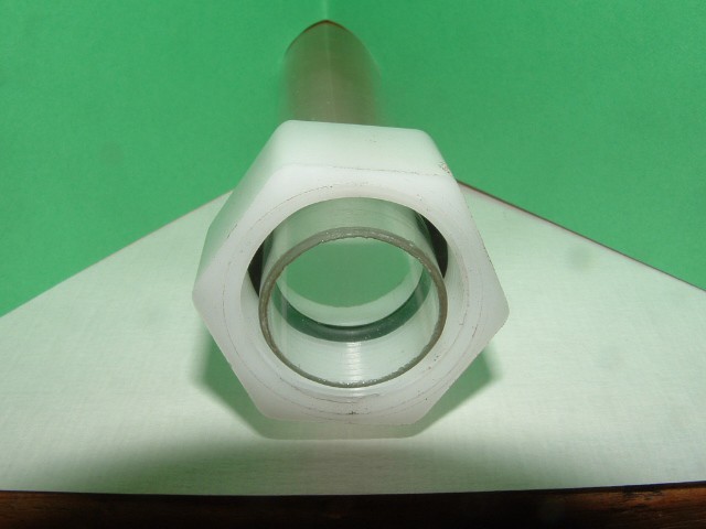
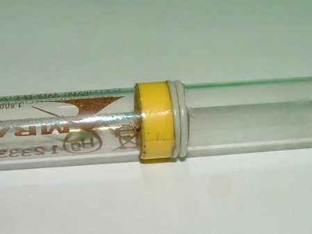
The one iinch glass tube was cut to length 36 " using a diamond cutter on a Dremil rotary cutter. This part is very critical. Slow and steady.
![]()
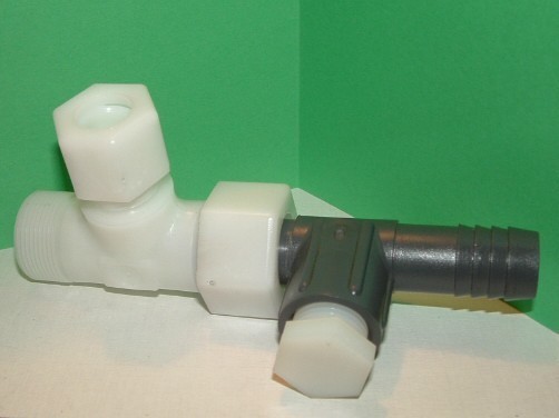
Water will be pumped through this chamber, cooling the laser tube. The O ring is all that seals the liguid because I did not want to use any permanent sealant. This will allow easy replacement of damaged components.
![]()
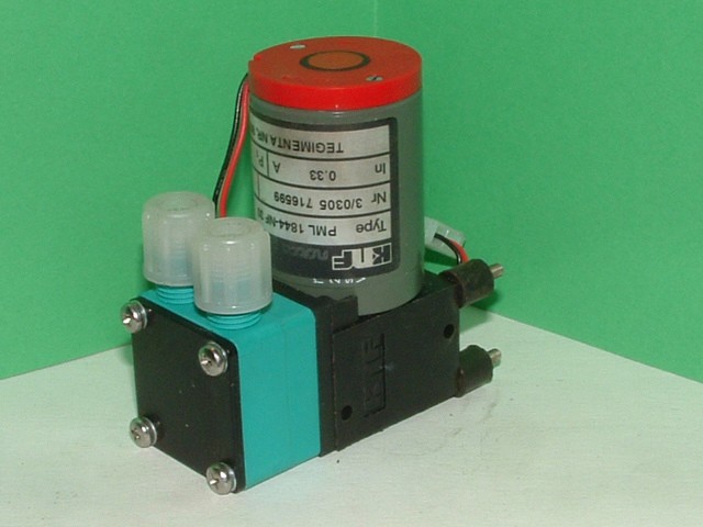
This is a 24Volt 7.8 watt fluid pump that I will be using for the cooling stage. It is fairly quiet and is rated as continuious duty.
![]()
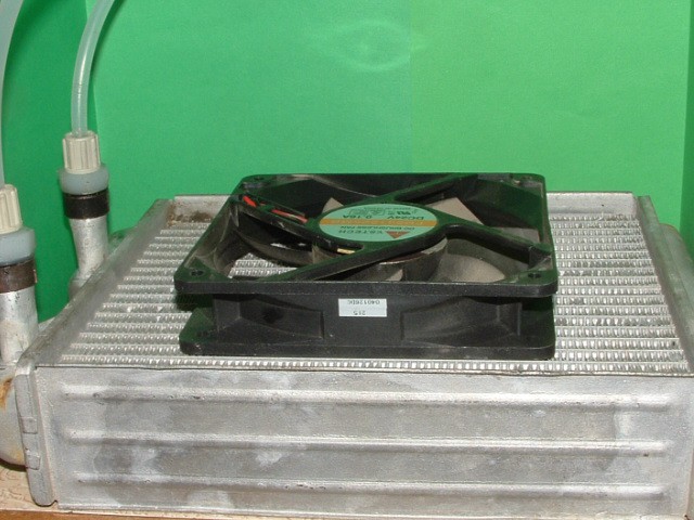
The cooling system is a closed loop. This unit is a salvaged heater core from an automobile. I shortened the hose connections and added some fittings. I will be using this 24v dc computer fan.
I will add an aluminium plate between the fan and core to duct the air through the heater core.
A small expansion chamber and filler cap will also be added to the loop.
It is important to keep the laser tube cool.
-
2Step 2
Construction of the laser tube:
- The laser tube was a used and salvaged from a water purifier. The ends were cut off with a diamond blade. A neon sign tube would also work.
WARNING: These tubes contain small amounts of mercury.
The Next series of pictures show the construction of the first stage of the end units.
![]()
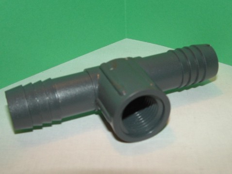
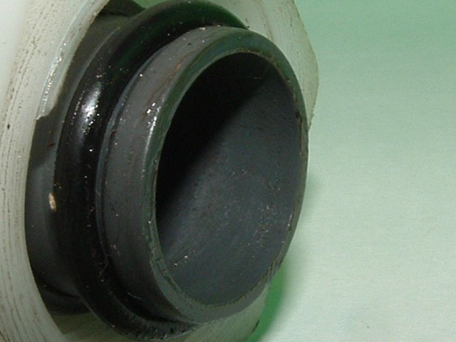
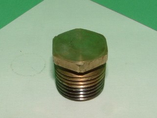
The fitting untouched.
![]()
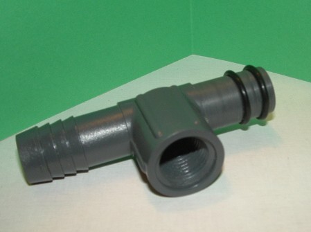
The fitting machined and two O Rings have been fitted.
![]()
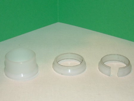
I modified one of the compression parts to clamp the first stage to the water jacket fitting..
![]()
Fitting ready to be connected. I used a small amount of petroleum jelly to assemble the two parts.
![]()
The middle nut clamps the first stage to the water jacket. The alignment is now perfect and sealed from the cooling fluid
![]()
Two silicone Orings are placed on the 1/2 laser tube and 1/4 inch mylar tape is wrapped around to stop the Orings from moving.
![]()
The fitting is machined with a tappered ream
![]()
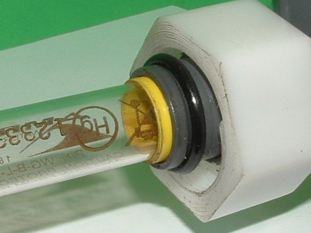
Here is the laser tube is inserted into the holder, sealed from the Liquid Coolent chamber.
-
3Step 3
Construction of the Anode and Cathode:
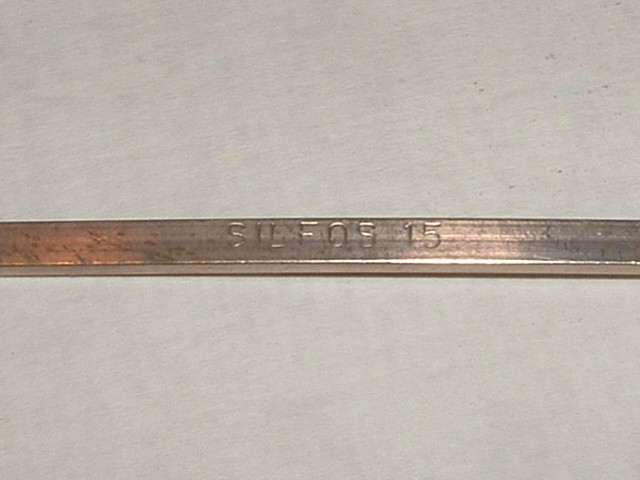
This material is Copper 85% and Silver 15%. SILFOS.
![]()
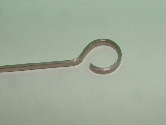
Here I have formed the Silfos around a pex barb fitting to achive this profile.
I clamped the end of the Silfos to the pex fitting with needle nose vice grips and then rotated it around the fitting. I then moved the grips and continued the rest of the curve. I cut the end to where the curve started. Last I formed the exit angle.
![]()
Here you can see the finished electrode with a 14 guage copper pin installed. I has also been cut to length. the shaft fits down into the 1/4" barb fitting,
![]()
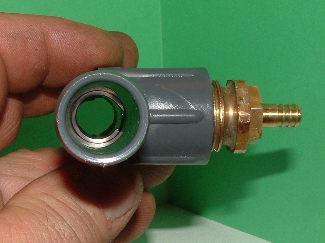
This is the Cathode and Anode holder;
![]()
I changed the Nylon fitting to Brass. This allows better heat conduction and better electrical connection. Next I drilled and tapped a 1/4" threaded hole in the center of the brass plug fitting and installed a barbed brass fitting,
![]()
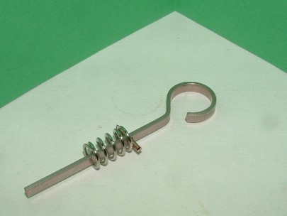
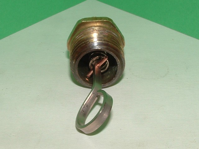
The assembeled spring loaded Cathode .
![]()
This end view shows the ring cathodes location. A Teflon washer is placed next to the cathode and the glass laser tube will rest up to the teflon ring. The Pumped Gas mixture will flow through the barb fitting into the laser tube.
-
4Step 4
Gas mixture and source:
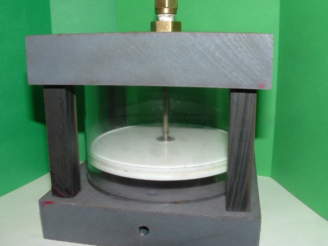
This is the gas litering piston assembly under construction. It is constructed of a 4" x 2/58" glass cylinder. The teflon piston seals completely and can evacuate 100% of the gas.
Volume is the V = Pi x r x (h - 1/4). V= 3.1415926 x 4 x 2.375 .
So my volume is 29.84513 cubic inches. ~ 30
The mixture:
1. ~ 10% carbon dioxide CO2
2. ~ 15% nitogen N2
3. ~ 75% helium He
![]()
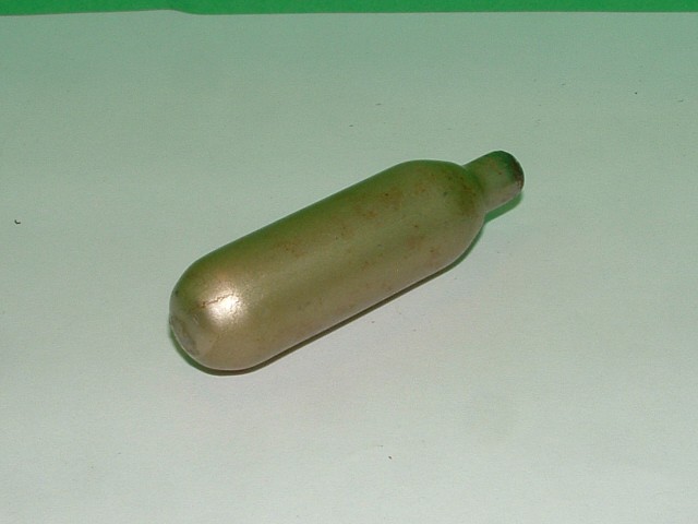
My source for the CO2 :
![]()
These refills for soda water contain 8 grams of liquid CO2. They fill a balloon several times.
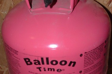
My source of He:
![]()
-
5Step 5
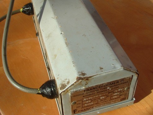
Construction of the Power Supply:
This is the Transformer that I will use to test the Laser. It is rated at 6000 volts and 30 mil amps.
It came from a small neon sign.
![]()
I will be using a fullwave doubler circuit that will give me ~ 12000 volts dc.
-
6Step 6
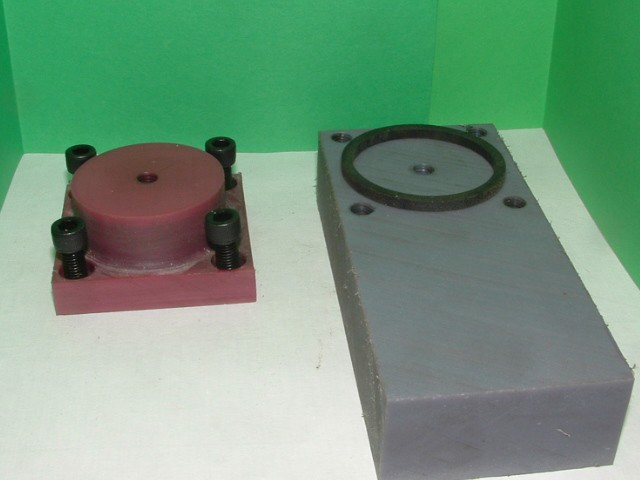
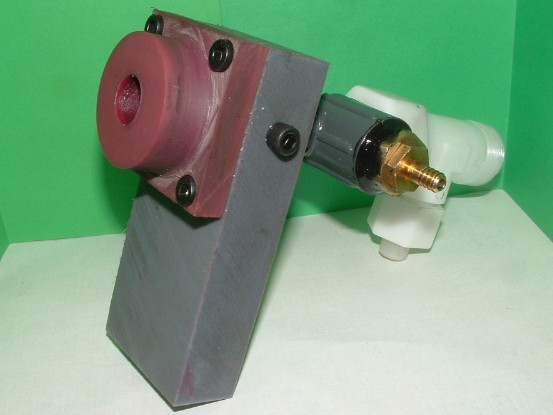
Mirror Mounts;
The rear mirror in this design will be a Silicone Plano-Concave 20 mm. The mirror sits in the machined red holder. The rubber ring seals the mirror holder to the main support , the four cap head screws allow perfect allignment of the rear mirror.
![]()
![]()
Here is the completed rear mirror mount connrctrd to the end assemblies.
-
7Step 7
Construction of the Enclosure:
Discussions
Become a Hackaday.io Member
Create an account to leave a comment. Already have an account? Log In.
Thanks for that. I will follow this with interest. It's the sort of project that I enjoy doing. It will be interesting to see the actual output. Best wishes and please keep posting about this
Are you sure? yes | no
interesting... Any idea of likely power output
Are you sure? yes | no
Thanks for your interest. The input electrical power is 60 Watt. I don't expect more than 20 Watts. 30 % efficiency.
Joseph.
Are you sure? yes | no
Work in progress, update as they become avaliable.
Are you sure? yes | no