AKA
AKA-
2017 update
11/14/2017 at 23:25 • 0 commentsHello!
This repo has gone significantly out of date. More recent information is available at weft.aka.farm, and I will be cleaning up and/or repurposing this hackaday project space in a little while!
Best,
AKA
-
Boost converter testing beginning soon
03/21/2016 at 14:19 • 0 commentsApologies for the lack of updates here - the project is most certainly still at the forefront of my attention, but I have been waylaid in the last month as I am changing jobs.
I will be taking Wednesday and Thursday to update this project, including some better documentation and project structure, as well as more verbose updates regarding the boost converter work.
I had OSHPark make a board (warning, board has not yet been validated by assembly/test) for prototyping the circuit described in the LM3478 application note here. My hope is to be able to tweak it with some component substitutions and get close to the values we'll need to make WEFT more reliable (the boost converter circuit will incorporate feedback, which is the main function missing from the current project).
-
Simplified Android app; upcoming goals
01/13/2016 at 17:51 • 0 commentstl;dr
I realized I was making two separate things in one Project, which is confusing, so I've simplified the project repo in the hopes of making it easier to jump into.
Splitting the project
I'm developing two things: one is the hobby board for WEFT, which will allow designers, prototypers, and hackers to easily integrate electrovibration into their projects. The other is a more focused device, a wearable that uses electrovibration to represent the state of your unread notifications.
This Hackaday project will be for the hobby board: the Hackaday audience is, I think, better served by focusing on that. Let me know if you disagree, and be assured, I'm still actively working on the wearable/notifications thing too!
Repo Cleanup and New Board
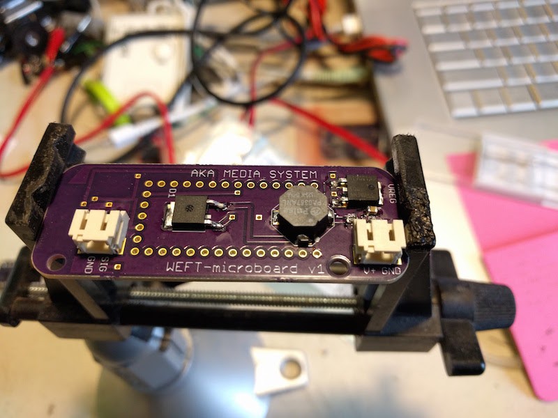
The github repo has been updated with a much-simpler Android app that allows the user to experiment with different waveforms, amplitudes, frequencies, and duty cycles. The board that interfaces with this app is the BLE-enabled board. Just to be clear, here's the BLE board:
![]()
The main problem with the BLE board (which I'm actively working on) is the BOM cost - it's currently just under $50, which is ridiculous. As I mentioned in a previous update, a huge amount of that cost comes from two microcontrollers, one for electrovibration and DAC stuff and one for BLE interfacing. I'm working steadily on ditching the Teensy, possibly for the RFduino or Simblee, possibly for some other appropriate microcontroller. I *really* don't want to get FCC certification, so an already-certified board is much preferred.
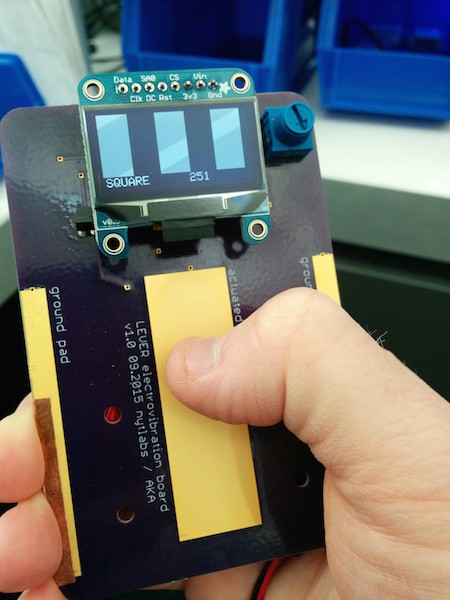
As the BLE board progresses, I'm realizing that it's ideal for embedding into projects but not as easy to just mess around with. The previous board I made, back at my day job, is slightly better for this. (For reference, the previous board is called "Lever" and is the handheld version that some of you got to try at the SuperConf). Here's the (old) Lever board:
![]()
So I think I'm going to start work on a new board, one that:
- Doesn't require BLE to change any settings
- Has as simple a BOM as possible
- Has an optional OLED display, showing waveforms and other settings
- Has an external interface for the electrovibration pad (though the Lever form factor is nice, ambidextrous, and intuitive, paying for all that empty board space was killer for the price point)
- A pushbutton+encoder knob for changing the WEFT parameters
- Has an off switch (I always forget this!)
This will basically be a board the size of the BLE board with some better routing and, if I'm lucky, a new and more robust version of the boost converter circuit. I thought briefly about perforating the Lever board, so that you could break off the pads when you were done prototyping and were ready to embed it into your prototype, but again, that's a lot of PCB to eventually throw away...what do you think?
Onward
So to summarize, the next things on the project docket are:
- Improve boost converter - this is long-term critical to WEFT, as without current-sensing feedback the user experience is pretty inconsistent across body types, different environments, etc.
- Fab a non-BLE board with the current circuit components and topology. This shouldn't take long, as I have the encoder code, etc all up and running in my studio.
- Find a way for the other folks on this project to get boards in their hands - if you have a mill you can probably make the boards yourself, otherwise we can do a group OSHPark order?
- Write a comprehensive post on how to safely experiment with the board. While I'm sure the board is relatively safe, it hasn't escaped my attention that I'm running a project with high voltage and trying to get people to touch it ;-)
- Improve the github readme by adding more references and background reading, safety guidelines, and adding graphics and images
OK! Am I missing anything? I'm loving the Hackaday.io interface and am very grateful that I'm getting such helpful, positive suggestions from the community - that's (one reason) why you-all rock!
-
Android progress and BOM rethink
12/21/2015 at 15:47 • 7 commentsI've made a fair amount of progress in the Android app over the last two weeks - nothing too exciting, but a steady stream of modest wins. You can check out the Github repo to see more, but the improvements are more frameworks-in-place for further development than they are new-features-to-try-out.
Meanwhile, a rough estimate of the BOM price was pretty eye-opening: the components (in single quantities, from Digikey) sum up to about $10, while the two microcontrollers I'm using sum to $36.
I've never spec'ed a project for any sort of scale manufacture, but this seems off to me. I always knew it was wasteful to use two micros, but kept with them for the convenience - there was a convenient separation of concerns that resulted from having the Teensy handle the PWM driving the boost converter (since Teensy's PWM frequency can be changed all the way up to ~400kHz) and its built-in hi-res DAC drive the high-voltage amplifier, while the RFduino just handles radio interactions.
Given that the next hardware change on my list is a big re-think of the boost converter circuit, now seems like a good moment to try to find a microcontroller that can do all the jobs I need:
- native/easy-to-use BLE interface
- relatively high-res analog out (I haven't tried putting a lowpass filter on the regular 8-bit analog out that RFduino can provide - I'll try to do that soon)
- Good battery life (though I won't be optimizing this for awhile yet)
- (possible) relatively high-res analog in for current sensing (if I end up doing this without another component like the ACS712)
- ...can anyone think of anything else?
...having a high-frequency PWM output seems like something I'd want on this list, but I found with the Teensy that it was easy to mess up the timing of the DAC output if I taxed other interrupt-driven stuff too much. As a result, this week I'll be trying to fit the boost converter stuff into a totally separate 555-based circuit that, hopefully, will be addressable by the microcontroller.
So far, I'm planning to work with RFduino for awhile and then migrate to Simblee, which is even smaller. But I'd love to hear anyone's two cents about the whole plan, as now is the time when the most variables are still undecided!
-
Android app in the repo now
11/23/2015 at 21:51 • 0 comments![]()
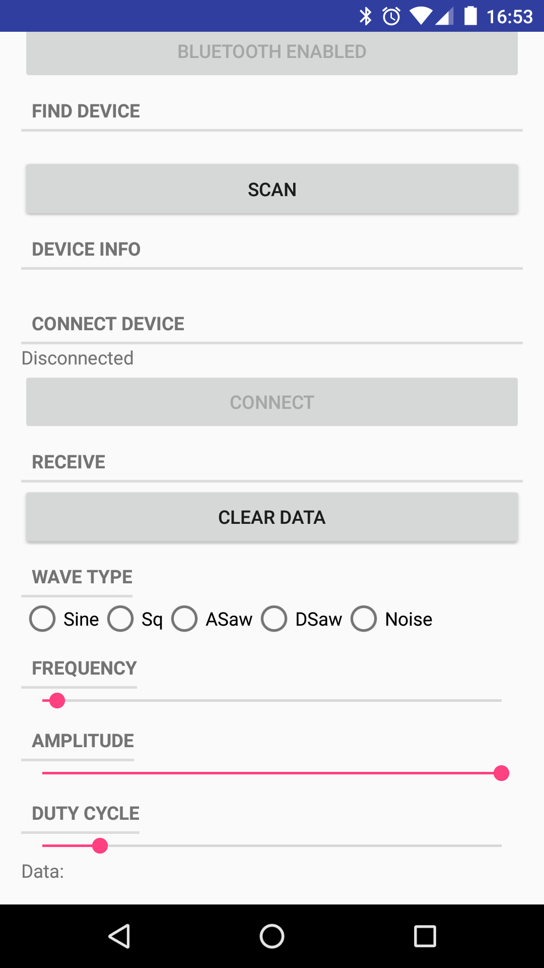
I found some time this weekend to get the dedicated Android app up and running.
Previously, I was sending two-byte transactions by hand using the excellent (but clunky, for my purposes) RFduino demo app by Github contributor Lann.
The new app is not much different, but it is the first step in building out a much more useful WEFT app. For now, there are sliders and radio buttons that automatically update the WEFT board with the selected parameters.
In the future, the "Duty cycle" adjustments won't be necessary (that will be controlled by the feedback logic on board), and other parameters will be testable/settable through a settings page. The current app is basically a prototype of that settings page.
In other news, I am looking for more-permanent pad coatings that have the same desirable dielectric properties as hairspray. I tried some nail polish topcoat, but I think the layer I applied was too thick, as it really diminishes the electrovibration effect. I'll keep trying with non-topcoat nail polish, as well as trying to thin nail polish with a bit of acetone, btu I'm wondering if the non-alcohol ingredients of hairspray are particularly good...if anyone has thoughts, chime in!
![]()
-
Hairspray surprise (update, confirmed!)
11/17/2015 at 20:41 • 10 commentsOlivier Bau, one of the authors of the two Disney Research papers the WEFT project is based on, was kind enough to meet with me recently and answer some of the questions I had after trying to implement the circuits described in the "Revel" paper.
The most surprising revelation was the choice of dielectric - the paper called for a thin non-conductive layer to be applied over the conductor, but no substance in my tests worked very well (I tried Kapton tape, packing tape, and a couple of other substances). Offhand, Olivier mentioned that spraying the copper with hairspray was ideal, and even enhanced the electrovibration sensation. Who knew?!
So once I recover form Hacakday SuperConference jetlag, I'll try this out. The procedure he recommended was to really drench the pad in hairspray and then let it dry vertically, so the excess runs off and leaves a thin, even layer as it dries.
-
What's next
11/15/2015 at 06:40 • 0 commentsThe WEFT board is working OK, but there are a couple component-selection factors to optimize.
More importantly, I'm hoping that making this project public will help move it into the realm of the really-useful - something that others might want to (and the be able to!) make for themselves.
To really make the electrovibration sensation reliable/repeatable across different people and environments, I need to figure out how to implement current-sensing feedback on the high-voltage side. This involves two tasks that I have failed at thus far: measuring the (tiny) current on the signal side, and then effectively modulating the boost converter circuit to account for the measured current.
At present, I suspect I'm operating with a pretty poor boost converter circuit - I can't get the voltage much higher than it is (which is still around 180v tops, a little more than half the voltage used by the Disney researchers), so Im' probably going to scrap the current transformer-based circuit and substitute in a 555-based boost circuit, closer to the Revel paper's implementation.
WEFT electrovibration demo board
This board is for prototyping electrotactile interactions - use an electronic signal to dynamically change the texture of a surface.