Jeroen van der Velden
-
The wooden frame Part 1
01/23/2016 at 18:48 • 0 commentsToday the MDF wood for the wooden frame arrived. My thanks goes out to my friend and sponsor Rob Haaksema from RH-Tendencia who made these parts available.
The first steps have been made to make the dashboard mobile for shows. I will upload more pictures and details very soon!
18mm MDF Wood was used. Don`t go any thinner, you need at least 18mm to carry the weight !!
1x 211.5cm by 55cm
1x 211.5cm bt 45.7cm
1x 211.5cm by 30cm
1x 211.5cm by 100cm
2x 69cm by 43cm (not correct, will update soon)
8 wheels 50kg each
Picture below:
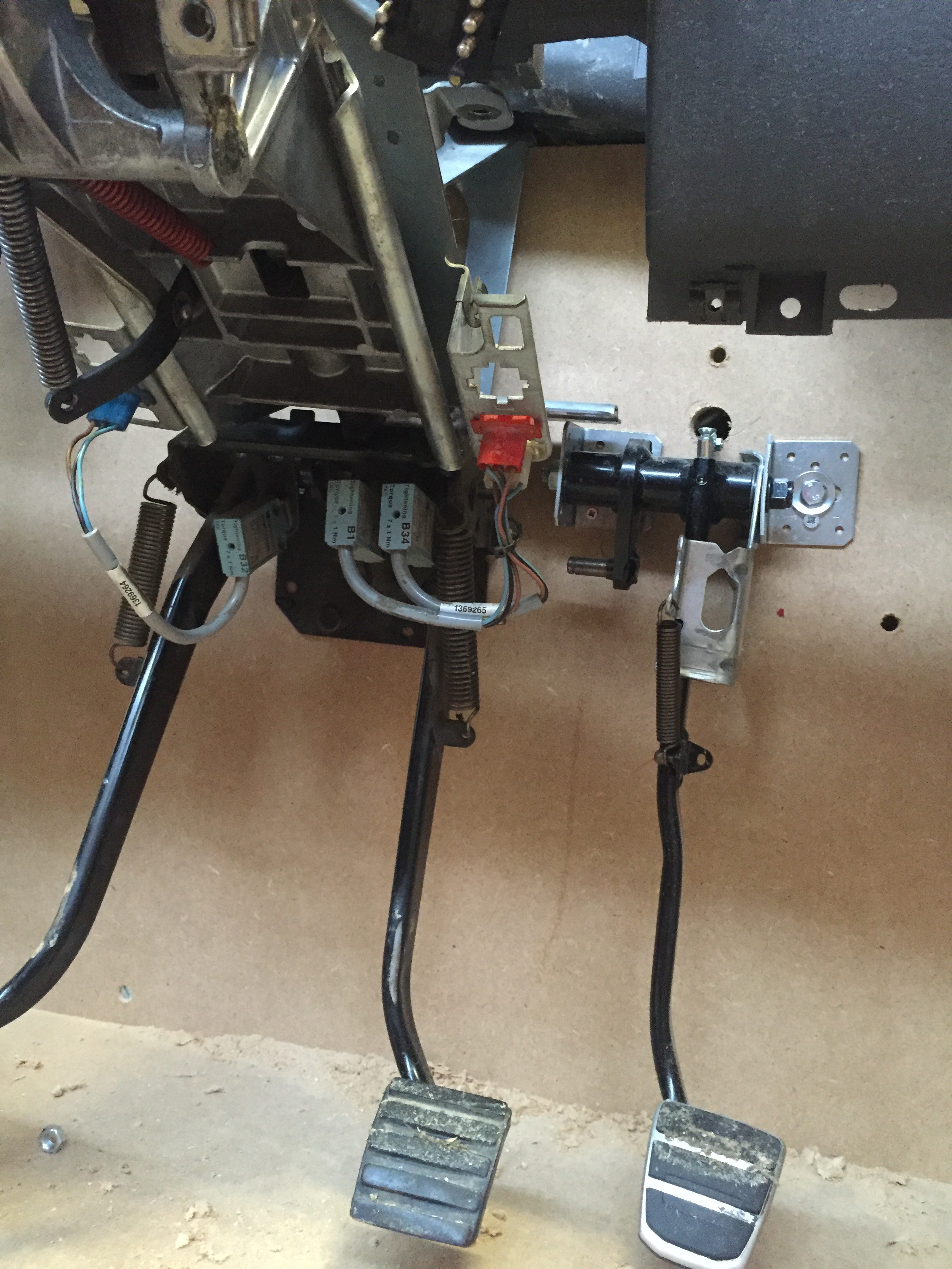
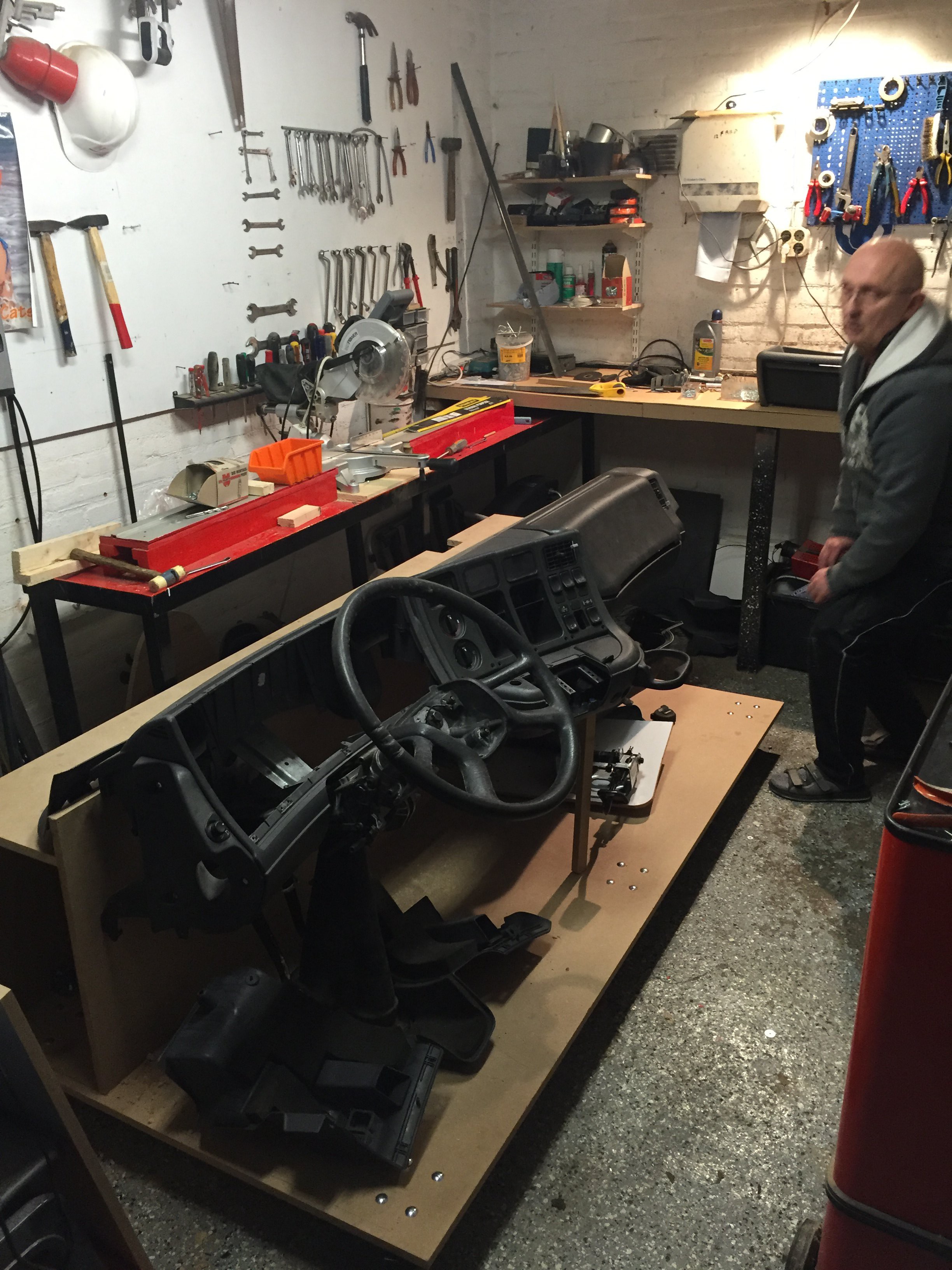
Unfortunately we started wrong. We have a 55cm high and a 45.7cm high panel in a 90 degree angle mounted on the floor (211.5cm by 100cm). At first as you can see in the second-last image we put the highest panel at the back which was wrong. The 55cm high panel seems to be the exact right height for the job. The good news is that you don`t need to cut away any wood which we did in the first attempt (see top right hole) to mount the steering column (very heavy weight). The steering column with clutch and brake pedal attached has 4 M8 thread ends and a pin in the middle that goes to the brake cilinder. These 4 threads will be the mounting solution for our simulator just like in a real truck. We don`t use the pin for the brake cilinder because we can use the CAN-BUS switches that are originally on this part for braking. We do leave the brake cilinder pin intact so we drill 4 holes for the M8 threads and one in the middle for the pin (more pictures with details soon).
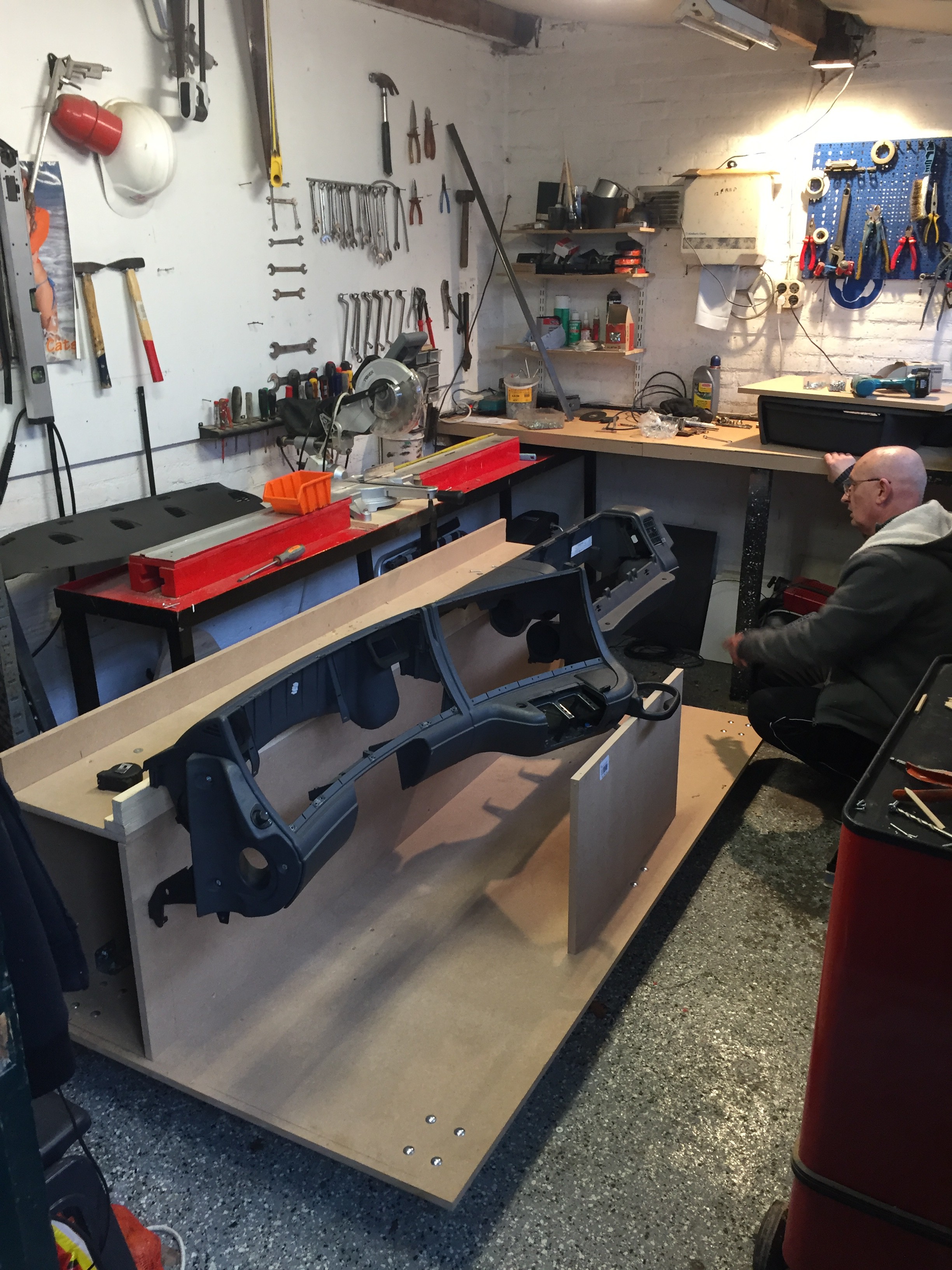
The dashboard itself has little screw-holes on the top that are being used to attach the dashboard to the MDF panel. If you use 18mm MDF like I did it all fits perfect and will carry the weight perfect and level the dash just right for the job. There are 2 extra supports on both ends of the dashboard to level the dashboard. Once the drawer (in the back at the bench) is in place it will also help to carry the weight of the dashboard. My guess is that the dashboard as on the 2nd picture below weights about 8kg. With steer, pedals and column as on the picture below it would weight about 25kg.
![]()
![]()
Picture below:
We started wrong with the high panel at the back. As you can see we tried to add wood strips to get our required height for our dashboard. At that very moment we started to realize we needed to swap panels to do it right.
If you look close you see the extra two wheels in the middle of the floor panel without shiny bold`s.
![]()
Picture below:
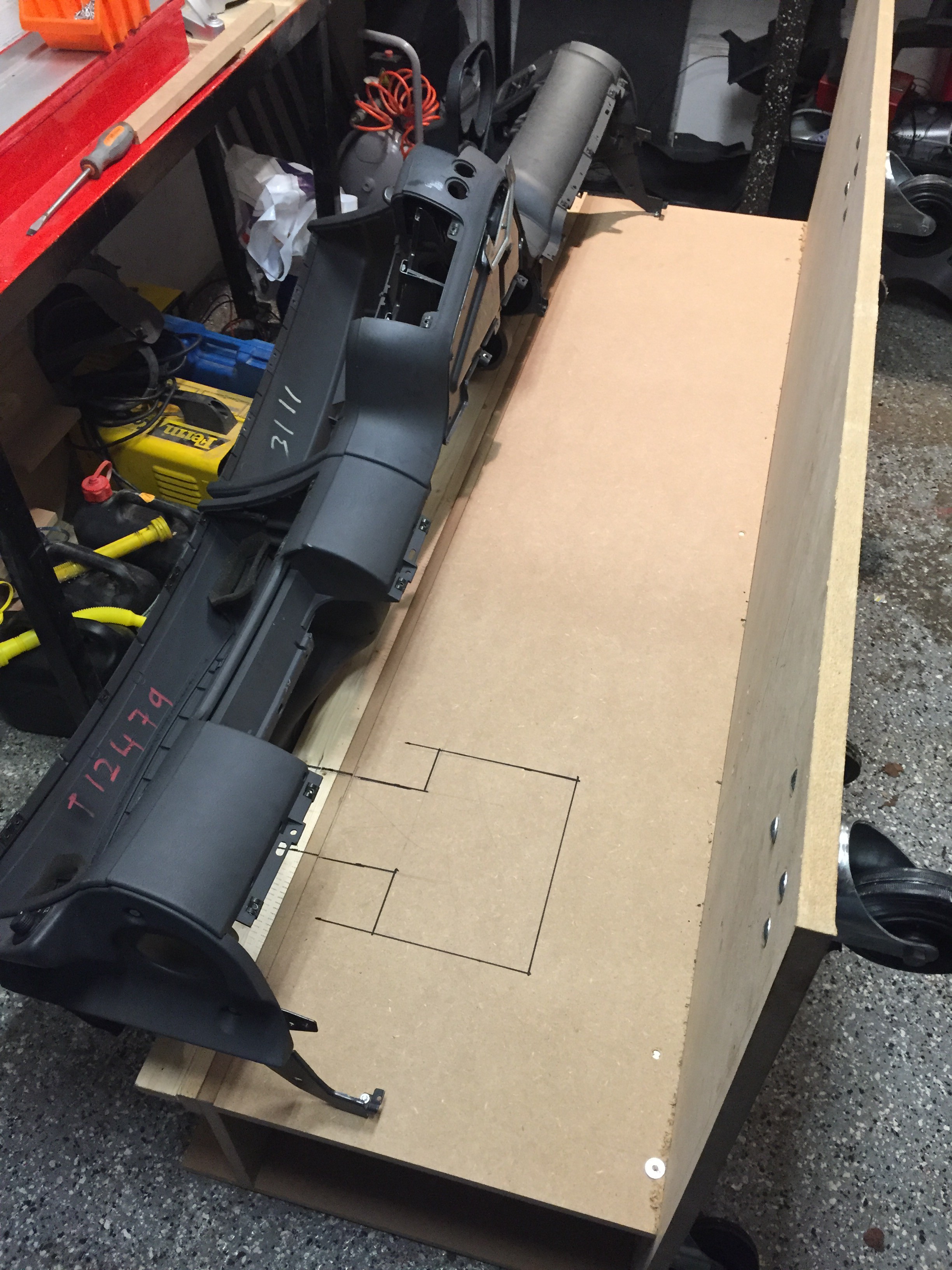
When we tried to fit the steering column my dad thought we needed to cut a hole in the back plate (black outlines). Unfortunately that was a big mistake and the wood we removed would have been just perfect to fit the column and carry the big weight of the steer and pedals.
So frustrating enough but with a clear goal in mind we removed the dashboard and both the upstanding wooden panels en we swapped them. The panel with the hole is now at the back of the simulator, its out of sight and the wrong cutout can later be used for easy access of cables and Arduino prints so its not that big of a problem.
![]()
Pictures below:
The started with just 6 wheels. We found out that 6 wheels just wasn`t enough to support our own weight and the MDF started to bend. We added 2 extra wheels in the middle (not on the picture). I would recommend to add a support frame on the bottom but that would add lots of weight to the whole thing.
![]()
![]()
![]()
-
ACC / EDC Cruise Control Part 3
12/30/2015 at 12:15 • 0 commentsHello folks!
We have been making slow progress on the ACC Handle code for Arduino. I`m using a Leonardo and so far we have a stable way of reading the ACC Values.
With the code below we can Serial Print and read the values. Next step will be stopping the loop and adding keyboard.Print commands.
Credits to Arduino Forum User UKHeliBob !!
// Arduino Leonardo Rev3.0 // This code is for all Scania 4-Series // ACC HID control for ETS2 void setup() { // initialize serial communication at 9600 bits per second: Serial.begin(9600); } // the loop routine runs over and over again forever: void loop() { // read the input on analog pin 0: int analogValue = analogRead(A0); // print out the value you read: Serial.println(analogValue); delay(100); // delay in between reads for stability if (analogValue > 870 && analogValue < 890) // read the analogue input into variable analogValue { //ACC is in the OFF Pos Serial.print("ACC OFF"); delay(1); } else if (analogValue > 950 && analogValue < 965) { //ACC is in the ON Pos Serial.print("ACC ON"); delay(1); } else if (analogValue > 985 && analogValue < 995) { //ACC is in the ON Pos and RET is Pressed Serial.print("ACC ON+RET"); delay(1); } else if (analogValue > 1000 && analogValue < 1011) { //ACC is in the ON Pos and RES is Pressed Serial.print("ACC ON+RES"); delay(1); } else if (analogValue > 1012 && analogValue < 1025) { //ACC is in the ON Pos and ACC is Pressed Serial.print("ACC ON+ACC"); delay(1); } } // Jeroen van der Velden // https://hackaday.io/project/8448-real-dashboard-truck-simulator![]()
-
Direction Indicators Part 1
12/21/2015 at 15:01 • 0 commentsMore info soon!
-
ACC / EDC Cruise Control Part 2
12/18/2015 at 13:38 • 0 commentsToday I started where I left with the ACC (Cruise Control). Now my code for the Retarder is ready and working, I might be able to use bits and pieces from the Retarder code to get the Cruise Control going.
In the Retarder LOGS I showed you that we had a 3 wire connection to our Arduino Leonardo. The Retarder is basically a 5v powered potentiometer.
The ACC buttons are two wire so we cant just put power on the line and measure voltage like with the Retarder. Actually we could, but I`d rather go for a two wire "Ohm Meter" setup because we know all the resistance values from the Scania Multi software.
Below is our setup, I soldered a 10k ohm resistor to my little board as our "known" resistor. The "unknown" resistor is each ACC button press. The code from the "Ohm Meter" tutorial will be modified to Keyboard.print our desired letter of choice for ETS2.
![]()
Above:
1# Connect 5v from your Leonardo to the White cable of the ACC connector
2# Connect A0 from your Leonardo to the Black/Purple wire of the ACC connector
3# Connect GND to one pole of your 10K ohm resistor
4# Connect A0 of the Leonardo to the other pole of the 10k ohm resistor
5# Check the picture above to double-check if everything is wired correctly
6# Download the code below to your Leonardo with Arduino IDE to test if all is right:
int analogPin= 0;
int raw= 0;
int Vin= 5;
float Vout= 0;
float R1= 10000;
float R2= 0;
float buffer= 0;

void setup()
{
Serial.begin(9600);
}

void loop()
{
raw= analogRead(analogPin);
if(raw)
{
buffer= raw * Vin;
Vout= (buffer)/1024.0;
buffer= (Vin/Vout) -1;
R2= R1 * buffer;
Serial.print("Vout: ");
Serial.println(Vout);
Serial.print("R2: ");
Serial.println(R2);
delay(1000);
}
}
// by Jeroen van der Velden
// https://hackaday.io/project/8448-real-dashboard-truck-simulator
7# Below should be your result on your Serial Monitor in the Arduino IDE software:![]()
8# Next step will be modifying code, I will keep you posted!
-
Word of thanks to Jeremy S Cook
12/17/2015 at 15:37 • 1 commentA word of thanks to Jeremy S Cook for posting my project on the Atmel.com embedded Design Blog..
Read here: Atmel Blog
![]()
-
Retarder Handle Part 5 (Final)
12/16/2015 at 11:49 • 1 commentI found it!! The final piece of this mind breaking code to connect a Scania 4-Series Retarder to your PC Home Truck Simulator.
How to Guide:
1# Buy a Scania Retarder Part No.1349967 Here or Here
2# Buy a cheap Arduino Leonardo
3# Upload my Code below with Arduino IDE to your Leonardo
4# Connect Retarder PIN 2 to Leonardo 5V, Connect Retarder PIN 6 to Leonardo PIN GND and Finally Connect Retarder PIN 7 to Leonardo PIN A0
5# Assign a key for your in-game Retarder (0 Decrease and 9 Increase) in the ETS2 Setting menu ***
6# Disable "Automatic Retarder" in the game settings in ETS2
7# Have fun!
***Instead of 0 and 9 you can also assign different keys in ETS2, but then you have to modify the code below a little bit. Just find Keyboard.print 0 and Keyboard.print 9 below.
![]()
unsigned long startTime, endTime = 1000; byte handlePos, oldHandlePos, currentPos; int8_t diff; int val; bool posSent = true; void setup() { Serial.begin(9600); val = getAnalog(); Serial.print("\nCurrent handle position = "); Serial.print(handlePos); Serial.println("\n\n"); currentPos = oldHandlePos = handlePos; } void loop() { val = getAnalog(); if(handlePos != currentPos) { startTime = millis(); currentPos = handlePos; posSent = false; diff = 0; } if(!posSent && millis() - startTime > endTime) { Serial.print("Handle Position = "); Serial.print(handlePos); Serial.print("\t"); diff = handlePos - oldHandlePos; Serial.print("Difference = "); Serial.println(diff); // if diff is negative number to positive number if(diff < 0) { for (int i = 0; i < (diff * -1); i++) { Keyboard.print("9"); delay(500); } } // if diff is positive number to positive number if(diff > 0) { for (int i = 0; i < diff; i++) { Keyboard.print("0"); delay(500); } } oldHandlePos = handlePos; posSent = true; } } int getAnalog() { val = analogRead(0); if(val < 187) handlePos = 0; else if(val < 350) handlePos = 1; else if(val < 518) handlePos = 2; else if(val < 679) handlePos = 3; else if(val < 861) handlePos = 4; else handlePos = 5; // Code by "Jeroen van der Velden" // Hackaday Project 8448 // https://hackaday.io/project/8448 }![]()
Next piece of Truck Hardware will be the Cruise Control. With this code and some modifications to the code we will be able to use the original Scania 4-series Cruisecontrol (ACC).Thanks for following!
-
Retarder Handle Part 4
12/13/2015 at 12:01 • 0 commentsSo close thanks to member OUTSIDER on the Arduino Forums!
The code below will tell us the handle position and difference between all positions just like in a real Scania!
![]()
Final challenge; keyboardPrint`s!
unsigned long startTime, endTime = 1000; byte handlePos, oldHandlePos, currentPos; int8_t diff; int val; bool posSent = true; void setup() { Serial.begin(9600); val = getAnalog(); Serial.print("\nCurrent handle position = "); Serial.print(handlePos); Serial.println("\n\n"); currentPos = oldHandlePos = handlePos; } void loop() { val = getAnalog(); if(handlePos != currentPos) { startTime = millis(); currentPos = handlePos; posSent = false; diff = 0; } if(!posSent && millis() - startTime > endTime) { Serial.print("Handle Position = "); Serial.print(handlePos); Serial.print("\t"); diff = handlePos - oldHandlePos; Serial.print("Difference = "); Serial.println(diff); oldHandlePos = handlePos; posSent = true; } } int getAnalog() { val = analogRead(0); if(val < 187) handlePos = 0; else if(val < 350) handlePos = 1; else if(val < 518) handlePos = 2; else if(val < 679) handlePos = 3; else if(val < 861) handlePos = 4; else handlePos = 5; return val; } // by Jeroen van der Velden // https://hackaday.io/project/8448-real-dashboard-truck-simulator // Credits to Arduino Forum member "OUTSIDER" -
Retarder Handle Part 3
12/12/2015 at 18:35 • 0 commentsWe are getting close my friends!
The code below stores and tells us the position of the retarder handle and it works perfect!
Connect the Retarder to an Arduino Leonardo:
Retarder PIN 2 to 5v
Retarder PIN 6 to gnd
Retarder PIN 7 to A0
int analogPin= 0;
int raw= 0;
int Vin= 5;
float Vout= 0;
float R1= 10000;
float R2= 0;
float buffer= 0;

void setup()
{
Serial.begin(9600);
}

void loop()
{
byte handlePos;
int val = analogRead(0);
  if(val < 187)
    {
      handlePos = 0;
      Serial.println("handlePos = 0");
      Serial.println(val);
    }
    else if(val < 350)
    {
      handlePos = 1;
      Serial.println("handlePos = 1");
      Serial.println(val);
    }
    else if(val < 518)
    {
      handlePos = 2;
      Serial.println("handlePos = 2");
      Serial.println(val);
    }
    else if(val < 679)
    {
      handlePos = 3;
      Serial.println("handlePos = 3");
      Serial.println(val);
    }
    else if(val < 861)
    {
      handlePos = 4;
      Serial.println("handlePos = 4");
      Serial.println(val);
    }
    else if(val < 1024)
    {
      handlePos = 5;
      Serial.println("handlePos = 5");
      Serial.println(val);
    }
    else
    {
    Serial.println("handlePos unknown");
    Serial.println(val);
    }
    delay(500);
}
// by Jeroen van der Velden
// https://hackaday.io/project/8448-real-dashboard-truck-simulator
//
Download link to Arduino IDE file
Next and final challenge: send keyboard commands "+" and "-" (retarder "up" and retarder "down")
-
Retarder Handle Part 2
12/11/2015 at 13:26 • 0 commentsStill working on the Retarder Lever, this code is driving me crazy!!!
I made slide 1 below to clear things up for you a bit. My Retarder handle is basically one big Potentiometer (5V, GND and A0). To Simulate this lever with Arduino, I made a breadboard with 6 Potentiometers (slide 2) on it. The pot`s are set to my levers resistance values *** to test my code. Although my lever has only 5 positions (1-5), there is also position 0 so I need 6 potentiometers on my breadboard.
Values***
With 5v connected to PIN 2 and 6 (PIN 2 +) (PIN 6 -):
Pos 0 = 0.53v
Pos 1 = 1.30v
Pos 2 = 2.12v
Pos 3 = 2.94v
Pos 4 = 3.69v
Pos 5 = 4.37v
Without 5v connected to PIN 2 and 6 (Resistance measured between PIN 7 and 2)
Pos 0 = no reading or infinite 4k+
Pos 1 = 1207 ohm
Pos 2 = 582 ohm
Pos 3 = 300 ohm
Pos 4 = 156 ohm
Pos 5 = 052 ohmSo far my code looks like:
byte handlePos;
int val = analogRead(0);

if(val < 100) handlePos = 0;
if(val < 187) handlePos = 1;
if(val < 350) handlePos = 2;
if(val < 518) handlePos = 3;
if(val < 679) handlePos = 4;
if(val < 861) handlePos = 5;
VAL (handle value) explained:
To determine val:
val = volts x 1023 / 5 = :
So:
Pos 0 = 0.53v * 1023 / 5 = 108 val
Pos 1 = 1.30v * 1023 / 5 = 266 val
Pos 2 = 2.12v * 1023 / 5 = 433 val
Pos 3 = 2.94v * 1023 / 5 = 602 val
Pos 4 = 3.69v * 1023 / 5 = 755 val
Pos 5 = 4.37v * 1023 / 5 = 967 val
So:
Pos 0 = 108
187
Pos 1 = 266
350
Pos 2 = 433
518
Pos 3 = 602
679
Pos 4 = 755
861
Pos 5 = 967Take averages (not sure if needed by now):
Pos 0 no val (infinite ohms or zero, needs further investigation)
Pos 1 (266 - 108) / 2 + 108 = 187
Pos 2 (433 - 266) / 2 + 266 = 350
Pos 3 (602 - 443) / 2 + 443 = 518
Pos 4 (755 - 602) / 2 + 602 = 679
Pos 5 (967 - 755) / 2 + 755 = 861
Now the handlePos`s are stored (byte) in the Arduino, I need to find code to:
When the lever goes DOWN one position, I need one HID keyboardPrint("+");
When the lever goes DOWN two positions, I need two HID keyboardPrint("+");`s
When the lever goes DOWN three positions, I need three HID keyboardPrint("+");`s
When the lever goes DOWN four positions, I need four HID keyboardPrint("+");`s
When the lever goes DOWN five positions, I need five HID keyboardPrint("+");`s
When the lever goes UP one position, I need one HID keyboardPrint("-")
When the lever goes UP two positions, I need two HID keyboardPrint("-");`s
When the lever goes UP three positions, I need three HID keyboardPrint("-");`s
When the lever goes UP four positions, I need four HID keyboardPrint("-");`s
When the lever goes UP five positions, I need five HID keyboardPrint("-");`s
When the lever is in position 3, and I move the lever to position five, I need two HID keyboardPrint("+");
Slide 1
![]()
Slide 2
![]()
More details in Retarder Handle Part 3!
-
Retarder Handle Part 1
12/07/2015 at 15:10 • 0 commentsCurrently I`m working on the Retarder Handle. Its a complicated piece because its a so called "Hall Effect Device" and it requires custom Arduino Code to make it work.
Hall Effect Devices output a specific voltage so the computer knows something changed. All Lever Positions have a specific ohms Resistance so we are going to measure the handles resistance with the Leonardo, store it in the Arduino`s memory and (Keyboard.print("a"); when the lever goes UP or we (Keyboard.print("b"); when the Lever goes DOWN.
I made this little board with the screw terminal on the bottom. Its not a nice piece I know, but it does the job. We will need this board in later steps for Part 2 of the ACC/EDC (cruise control) log as well.
![]()
I found This Online Tutorial. It tells you how to build an ohm meter with Arduino. I will post the modified Arduino Code for ETS2 in the next step (Retarder part 2).For now I need to keep testing and looking for code, I will keep you posted!
Real Scania Truck Home Simulator
The Scrapyard and Arduino make a great combination!